EP4404053A1 - Verfahren zum flashing einer an einem fahrzeug montierten ecu, fahrzeug und speichermedium - Google Patents
Verfahren zum flashing einer an einem fahrzeug montierten ecu, fahrzeug und speichermedium Download PDFInfo
- Publication number
- EP4404053A1 EP4404053A1 EP22866763.0A EP22866763A EP4404053A1 EP 4404053 A1 EP4404053 A1 EP 4404053A1 EP 22866763 A EP22866763 A EP 22866763A EP 4404053 A1 EP4404053 A1 EP 4404053A1
- Authority
- EP
- European Patent Office
- Prior art keywords
- ecu
- flashing
- vehicle
- program
- boot mode
- Prior art date
- Legal status (The legal status is an assumption and is not a legal conclusion. Google has not performed a legal analysis and makes no representation as to the accuracy of the status listed.)
- Granted
Links
Images



Classifications
-
- G—PHYSICS
- G06—COMPUTING OR CALCULATING; COUNTING
- G06F—ELECTRIC DIGITAL DATA PROCESSING
- G06F8/00—Arrangements for software engineering
- G06F8/60—Software deployment
- G06F8/65—Updates
- G06F8/654—Updates using techniques specially adapted for alterable solid state memories, e.g. for EEPROM or flash memories
-
- G—PHYSICS
- G06—COMPUTING OR CALCULATING; COUNTING
- G06F—ELECTRIC DIGITAL DATA PROCESSING
- G06F9/00—Arrangements for program control, e.g. control units
- G06F9/06—Arrangements for program control, e.g. control units using stored programs, i.e. using an internal store of processing equipment to receive or retain programs
- G06F9/44—Arrangements for executing specific programs
- G06F9/4401—Bootstrapping
Definitions
- the present application relates to the field of vehicle technologies, and more particularly, to a method for flashing a vehicle-mounted ECU, a vehicle, and a storage medium.
- An electronic control unit is one of core components of a vehicle.
- the ECU When the ECU has a fault or a program of the ECU needs to be upgraded, the ECU needs to be disassembled from the vehicle, and the ECU is flashed manually through a specific device, a large amount of time needs to be consumed in a whole flashing process of the ECU.
- One of the objects of the embodiments of the present application is to provide a method for flashing a vehicle-mounted ECU, a vehicle, and a storage medium.
- a method for flashing a vehicle-mounted ECU includes:
- the method before entering the emergency boot mode, the method includes:
- the first pin is a pull-up pin of an Ethernet activation line.
- the first operation includes at least one of a braking operation, a key press operation on an air conditioning, and a key press operation on a steering wheel.
- the detecting whether the first operation is exerted includes:
- the method includes:
- the method includes:
- an electronic control unit includes:
- a vehicle in accordance with the third aspect, includes: a memory, an ECU and a computer program stored in the memory and executed on the ECU, where the ECU is configured to implement any method for flashing the vehicle-mounted ECU in the first aspect, when executing the computer program.
- a computer-readable storage medium stores a computer program, where when the computer program is executed by a processor, any method for flashing the vehicle-mounted ECU in the first aspect is implemented.
- a computer program product is provided.
- the terminal device is caused to perform any method for flashing the vehicle-mounted ECU in the first aspect.
- the ECU may detect whether the first operation is performed on the vehicle. If the first operation is performed, and the time duration of the first operation is greater than the preset threshold value, the ECU enters the emergency boot mode. The ECU obtains the first-data-to-be-flashed after entering the emergency boot mode, and completes flashing of the ECU based on the first-data-to-be-flashed. As compared to the existing method in which the flashing of the ECU can be implemented only when the ECU is disassembled from the vehicle, in the present application, the ECU can be flashed without being disassembled, such that the ECU can be flashed more simply and efficiently.
- An electronic control unit generally has fault self-diagnosis and protection function.
- the system may automatically record a fault code in a random access memory (RAM) or a Flash and use a protection measure to read an alternative program from a firmware to maintain a function (e.g., a function of a safety lamp) that must be maintained.
- RAM random access memory
- Flash Flash
- FIG. 1 is a schematic diagram of an application scenario of the method for flashing the vehicle-mounted ECU according to one embodiment of the present application.
- the method for flashing the vehicle-mounted ECU may be used for upgrading the ECU of the vehicle.
- a computer 10 is configured to store data to be flashed
- the ECU 20 is configured to obtain the data to be flashed from the computer 10 when determining that a flashing operation needs to be performed, so that the data to be flashed is flashed into the ECU.
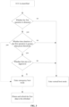
- FIG. 2 and FIG. 3 illustrate a schematic flowchart of the method for flashing the vehicle-mounted ECU according to the present application.
- the method includes steps S101 to S 104.
- the ECU detects whether a first operation is performed.
- a process from powering off of the ECU to powering on of the ECU is referred to as a restart process.
- the ECU detects whether the first operation is performed on the vehicle on which the ECU is mounted within a preset time, after each restart.
- the preset time may be set as required. For example, the preset time may be set to 50 seconds, 60 seconds, 70 seconds, or the like.
- the first operation may be set as needed.
- the first operation may include at least one of a braking operation, a key press operation on an air conditioning, and a key press operation on a steering wheel.
- the key press operation on the steering wheel may include a turn signal lamp turn-on operation, a wiper turn-on operation, a horn turn-on operation, and the like.
- a method for detecting the first operation may include: obtaining a level signal of a preset circuit in the vehicle; determining that the first operation is detected if the level signal meets the preset operation requirement.
- the preset circuit may be a circuit corresponding to a brake switch, a circuit corresponding to an air conditioner switch, a switch corresponding to the operation on the steering wheel, and the like. If the preset circuit includes a circuit corresponding to the brake switch, the preset operation requirement includes a braking operation. If the preset circuit includes a circuit corresponding to the air conditioner switch, the preset operation requirement includes an air conditioner start operation. If the preset circuit includes a circuit corresponding to the switch that corresponds to the operation on the steering wheel, the preset operation requirement includes a start-up operation of a corresponding device on the steering wheel.
- the detection of the key press operation on the air conditioner may include: obtaining a level signal of a switch of the air conditioner, if the level signal meets the start-up requirement, for example, the level signal is at a high level, the key press operation on the air conditioner is detected.
- the key press operation on the steering wheel may be detected, the details of the key press operation on the steering wheel are not repeatedly described herein.
- step S101 may include: In the step of S 1011, a level signal of the brake switch in the vehicle is obtained.
- the brake switch of the vehicle may be controlled by two lines. Specifically, the brake switch may be controlled together by a line 1 and a line 2. When the line 1 is at a low level and the line 2 is at a high level, the brake switch is in a non-braking state. When the line 1 is at a high level and the line 2 is at a low level, the brake switch is in a braking state. The ECU may determine whether the brake switch is in a braking state according to the level signal of the brake switch.
- a step of S 1012 if the level signal of the brake switch meets the braking requirement, it is determined that the first operation is detected.
- step of S1013 if the level signal of the brake switch does not meet the braking requirement, it is determined that the first operation is not detected.
- a condition that the level signal of the brake switch meets the braking requirement includes: the line 1 is at the high level, and the line 2 is at the low level.
- step of S 102 if the first operation is detected, time duration of the first operation is obtained.
- timing may be started, and the time duration of the first operation is obtained by timing.
- the first operation needs to be continuously detected during timing so as to determine whether the first operation is continued to be performed. If the first operation is not detected, it can be determined that performing of the first operation is no longer continued.
- a current time of the timer in the ECU may be recorded, and this time may be recorded as an initial time in the present application.
- the time duration of the first operation may be obtained according to a difference value between the current time of the timer and the initial time.
- the current time of the timer is 10 when the first operation is detected, performing of the first operation is still continued at the current time, when the current time timer is 15, the performing of the first operation has be lasted for 5 seconds.
- the emergency boot mode is entered.
- a condition of the ECU for entering the emergency boot mode is determined, and the ECU may enter the emergency boot mode.
- the emergency boot mode may be a boot mode before a normal operation process.
- the preset threshold value may be set as required.
- the preset threshold value may be set to 5 seconds, 8 seconds, 10 seconds, or the like.
- the ECU enters the emergency boot mode if the preset time is 5 seconds, and it is detected that the first operation has been lasted for 6 seconds at the current time, it is determined that the time duration of the first operation is greater than the preset threshold value, the ECU enters the emergency boot mode.
- the start-up sequence of the programs in the ECU is boot program->App program (application program), the application program will be operated only after execution of the boot program is completed.
- the application program in the ECU is not executed in the emergency boot mode.
- Bootloader that is, the boot program
- the boot program may be executed in the emergency boot mode.
- the boot program is a boot file of the system, and may be used to guide the ECU to enter an operating system.
- the boot program is used to complete an entire system boot process of locating kernel codes in an external memory, and putting the kernel codes into the memory and finally enabling the kernel to be operated according to requirements.
- the boot program needs to complete a plurality of initialization processes, various services of the system may be used only after the processes are completed successfully. These processes include initial boot, kernel initialization, initialization of the entire system.
- step of S 104 first-data-to-be-flashed is obtained and is flashed into the ECU.
- the ECU may obtain the data to be flashed from an external computer. Specifically, after obtaining the data from the computer, the ECU may determine whether the version of the currently stored data in the ECU is the same as the version of the obtained data. If the version of the currently stored data in the ECU is the same as the version of the obtained data, the obtained data may be used to replace the currently stored data; or alternatively, the data may not be processed. If the version of the currently stored data in the ECU is different from the version of the obtained data, the obtained data may be stored in a Flash to complete flashing of the ECU. In the present application, the data obtained from the computer is referred to as the first-data-to-be-flashed.
- the ECU may detect whether the first operation is performed on the vehicle. If the first operation is detected, the time duration of the first operation may be obtained to determine whether the emergency boot mode may be entered. If the time duration of the first operation is greater than the preset threshold value, the ECU enters the emergency boot mode. The ECU obtains the first-data-to-be-flashed after entering the emergency boot mode, and completes flashing of the ECU based on the first-data-to-be-flashed. According to the present application, the ECU can be flashed without being disassembled. Thus, the flashing of the ECU is simpler and more efficient. In addition, according to the present application, the condition for entering the emergency boot mode is set, the emergency boot mode can be entered only when the condition for entering the emergency boot mode is met, the flashing of the ECU in an unexpected condition is avoided.
- an Ethernet communication interface on the ECU may be utilized to perform wired connection with the computer, in order to obtain the data to be flashed from the computer being in wired connection with the ECU.
- the computer may be connected to an on board diagnostics (On Board Diagnostics, OBD) system interface through a network cable.
- OBD On Board Diagnostics
- the OBD interface is connected to the Ethernet communication interface in the ECU, and a communication between the computer and the ECU is implemented through the OBD interface.
- the computer may be connected to ETHERNET TX+, ETHERNET TX-, ETHERNET RX+ and ETHERNET RX- in the OBD interface through the network cable.
- RX represents signal reception
- TX represents signal transmission, referring to the schematic diagram of the OBD interface shown in FIG. 5 , pin 3 is ETHERNET RX+, pin 11 is ETHERNET RX-, pin 12 is ETHERNET TX +, pin 13 is ETHERNET TX-.
- Activation of the Ethernet communication interface requires control of an enable signal. If the enable signal exists, communication may be performed through the Ethernet communication interface, otherwise, communication cannot be performed through the Ethernet communication interface.
- a signal of a pull-up pin on Ethernet activation line in the OBD interface may provide the enable signal for the Ethernet communication interface, and a positive electrode of a storage battery of the vehicle may be connected to the pull-up pin of the Ethernet activation line in the OBD interface through a wire, such that the level signal of the pull-up pin of the Ethernet activation line is at a high level.
- the pin 8 is a pull-up pin of the Ethernet activation line.
- the pull-up pin of the Ethernet activation line is at the high level, the Ethernet communication interface is in a switched on state.
- the pull-up pin of the Ethernet activation line is at a low level, the Ethernet communication interface is in a switched off state.
- the pull-up pin of the Ethernet activation line may be referred to as the first pin.
- the condition that the ECU enters the emergency boot mode may further include: detecting a level signal of the first pin of the OBD interface connected to the Ethernet communication interface of the vehicle, and entering the emergency boot mode if the level signal is a high-level signal and the time duration of the first operation is greater than a preset threshold value.
- the level signal of the first pin when the level signal of the first pin is at the high level, it may be determined that the Ethernet communication interface is in a switched on state, in order to ensure that the ECU may obtain the first-data-to-be-flashed from the computer through the Ethernet communication interface.
- the first pin being at a high level is used as a condition for entering the emergency boot mode, to ensure that the ECU can perform data flash successfully after entering the emergency boot mode.
- the aforementioned method may further include: if the first operation is not detected within a preset time after the ECU is electrified, a normal boot mode is entered. If the time duration is less than or equal to the preset threshold value, and/or the level signal of the first pin is at a low level, the normal boot mode is entered.
- the ECU may normally execute application programs in the ECU in the normal boot mode, and the application programs in the ECU may include a lamp lighting up program, a screen turning on program, a vehicle ignition program, and the like.
- the ECU if the first operation is detected, however, the time duration of the first operation is less than or equal to the preset threshold value, the ECU does not meet the condition of entering the emergency boot mode, and the ECU enters the normal boot mode.
- the normal boot mode is a mode in which the ECU is started-up and executes an application program in the ECU. After entering the normal boot mode, the ECU executes the boot program firstly, and executes the application program after execution of the boot program is completed.
- a flashing device may be utilized to transmit data to be flashed to the ECU, thereby completing flashing of the ECU.
- the method includes: In a step of S201, an application program in the ECU is executed.
- a fault code of the fault program is sent to the flashing device if the application program has a fault and a fault query instruction sent by the flashing device is received.
- the flashing device may be a vehicle fault diagnosis instrument.
- the automobile fault diagnosis instrument is a vehicle fault self-diagnosis terminal device, and is a portable intelligent vehicle fault self-diagnosis instrument for detecting vehicle fault, and a user may use this instrument to quickly read faults of various ECUs of vehicles, and quickly determine a faulty part and the reason of fault according to the displayed fault information.
- the ECU if the application program has a fault, the ECU generates the fault code of the fault program.
- the user may send the fault query instruction to the ECU through the flashing device. After receiving the fault query instruction sent by the flashing device, the ECU sends the fault code of the fault program to the flashing device.
- the flashing device After receiving the fault code, the flashing device parses the fault code to obtain a fault application corresponding to the fault code, and displays the fault application to the user.
- the flashing device searches corresponding data to be flashed according to the fault application, the corresponding data to be flashed is referred to as the second-data-to-be-flashed in the present application.
- the flashing device generates a program flashing command according to the second-data-to-be-flashed, and sends the program flashing command to the ECU.
- the flashing device may send inquiry information to the ECU. If the ECU receives the inquiry information sent by the flashing device, the ECU may return an acknowledging command to the flashing device. After receiving the acknowledging command sent by the ECU, the flashing device sends the program flashing command to the ECU.
- step of S203 the program flashing command sent by the flashing device is received, and flashing is performed using the second-data-to-be-flashed contained in the program flashing command.
- the program flashing command may include an identifier of an application program to be flashed and the second-data-to-be-flashed.
- the identifier may be comprised of numbers, letters, symbols, and the like. Each application program corresponds to one identifier uniquely.
- the ECU parses the program flashing command to obtain the second-data-to-be-flashed of the application program to be flashed, and then performs flashing using the second-data-to-be-flashed.
- the processing of the second-data-to-be-flashed by the ECU is the same as the processing of the first-data-to-be-flashed.
- the processing of the second-data-to-be-flashed by the ECU can refer to the descriptions of the step S104, and is not repeatedly described herein.
- the flashing device may further send flash data of the application program of the latest version to the ECU.
- the ECU receives the flash data of the application program of the latest version sent by the flashing device, and stores the flash data of the application program of the latest version.
- the implementation process of the step S202 may include: In a step of S2021, state information of the vehicle is obtained.
- the ECU may obtain the state information of the vehicle.
- the state information of the vehicle may include a vehicle speed, an engine speed, a power switch position, and the like.
- the obtaining of the state information of the vehicle is used for determining whether the vehicle is in an operating state. If the vehicle is in the operating state, the ECU cannot be flashed. Specifically, the vehicle speed and the engine speed are used to determine whether the vehicle is in a stationary state.
- the power switch position is used to determine whether an electronic device in the vehicle is electrified.
- the vehicle speed is within a first preset range, whether the engine speed is within a second preset range, and whether the power switch position is at an ON position may be determined.
- the power switch supplies power to all electronic devices in the vehicle when the power switch position is at the ON position.
- the first preset range and the second preset range may be set as needed.
- the fault code of the fault program is sent to the flashing device if the state information meets the preset requirement.
- the state information meeting the preset requirement includes the vehicle speed is within the first preset range, the engine speed is within the second preset range, and the power switch position is at the ON position.
- the status of the vehicle is determined before flashing, the ECU is flashed when the vehicle state information meets the requirement, so that a phenomenon of vehicle failure caused by flashing during driving of the vehicle may be avoided.
- FIG. 7 illustrates a structural block diagram of an electronic control unit (ECU) according to one embodiment of the present application.
- ECU electronice control unit
- the ECU 300 may include a detection module 310, a time test module 320, a mode selection module 330 and a program flashing module 340.
- the detection module 310 is configured to detect whether a first operation is performed after the ECU is electrified, where the first operation is an operation performed on a vehicle on which the ECU is mounted.
- the time test module 320 is configured to obtain time duration of the first operation after the first operation is detected.
- the mode selection module 330 is configured to enter an emergency boot mode if the time duration is greater than a preset threshold value, where an application program in the ECU is not executed by the ECU in the emergency boot mode.
- the program flashing module 340 is configured to obtain first-data-to-be-flashed and use the first-data-to-be-flashed to perform flashing.
- the mode selection module 330 may be further configured to:
- the first pin is a pull-up pin of an Ethernet activation line.
- the first operation includes at least one of a braking operation, a key press operation on an air conditioning, and a key press operation on a steering wheel.
- the detection module 31 may be specifically configured to:
- the program flashing module 340 may be specifically configured to:
- the program flashing module 340 may be specifically configured to:
- the dividing of the aforementioned various functional units and modules is merely described as examples.
- the aforementioned functions may be assigned to functional units and modules to be accomplished, that is, an inner structure of the device is divided into different functional units and modules for accomplishing the whole or a part of functionalities described above.
- the various functional units and modules in the embodiments may be integrated into one processing unit, or each of the units exists independently and physically. As an alternative, two or more than two of the units are integrated into one single unit.
- the aforementioned integrated units may either by actualized in the form of hardware or in the form of software functional units.
- the vehicle 400 includes an ECU 410, a memory 420, and a computer program stored in the memory 420 and executable by the ECU 410.
- the ECU 410 is configured to implement the steps (e.g., the steps S101-S104 in the embodiments shown in FIG. 2 ) in the various method embodiments when executing the computer program.
- the ECU 410 is configured to implement the functions of the various modules/units (e.g., the modules 310-340 as shown in FIG. 7 ) in the various apparatus embodiments when executing the computer program.
- the computer program may be divided into one or a plurality of modules/units, the one or plurality of modules/units are stored in the memory 420, and executed by the ECU 410 so as to implement the present application.
- the one or plurality of modules/units may be a series of computer program instruction segments that can accomplish particular functionalities, these instruction segments are used for describing an executive process of the computer program in the vehicle 400.
- FIG. 8 is merely an example of the vehicle, and is not constituted as limitation to the vehicle, more or less components than the components shown in FIG. 8 may be included, or some components or different components may be combined.
- the vehicle may also include an input and output device, a network access device, a bus, etc.
- the ECU 410 may be central processing unit (CPU), and may also be other general purpose processor, digital signal processor (DSP), application specific integrated circuit (ASIC), field-programmable gate array (FGPA), or some other programmable logic devices, discrete gate or transistor logic device, discrete hardware component, etc.
- the general purpose processor may be a microprocessor, as an alternative, the processor can also be any conventional processor, or the like.
- the method for flashing the vehicle-mounted ECU provided in the embodiments of the present application may be applied to terminal devices such as computers, tablets, laptops, netbooks, personal digital assistants (PDAs), etc.
- terminal devices such as computers, tablets, laptops, netbooks, personal digital assistants (PDAs), etc.
- PDAs personal digital assistants
- the specific types of the terminal devices are not limited in the embodiments of the present application.
- a computer-readable storage medium is further provided in the embodiments of the present application.
- the computer-readable storage medium stores a computer program, when the computer program is executed by a processor, steps of the various method embodiments for flashing the vehicle-mounted ECU may be implemented.
- a computer program product is provided in the embodiments of the present application.
- the mobile terminal is caused to implement the steps of the various method embodiments for flashing the vehicle-mounted ECU.
- the integrated modules When the integrated modules are achieved in the form of software functional units, and is sold or used as an independent product, the integrated modules may be stored in a computer-readable storage medium. Based on this understanding, a whole or part of flow process for implementing the method in the embodiments of the present application can also be accomplished in the manner of using computer program to instruct relevant hardware. When the computer program is executed by the processor, the steps in the various method embodiments described above may be implemented.
- the computer program comprises computer program codes, which may be in the form of source code, object code, executable documents or some intermediate form, etc.
- the computer readable medium may at least include: any physical equipment or device that can carry the computer program codes to a photographing device/terminal device, recording medium, computer memory, ROM (Read-Only Memory), RAM (Random Access Memory), electrical carrier signal, telecommunication signal and software distribution medium, such as USB flash disk, mobile hard disk drive, diskette or optical disk.
- the computer readable medium doesn't include electrical carrier signal and telecommunication signal.
- the disclosed apparatus/network devices and the methods could be implemented in other ways.
- embodiments of the apparatuses/network devices described above are merely illustrative.
- the division of the units is only a logical function division, and other division could be used in the actual implementation, for example, multiple units or components could be combined or integrated into another system, or some features may be ignored, or not performed.
- the coupling or direct coupling or communicating connection shown or discussed could be an indirect coupling or a communicating connection through some interfaces, devices or units, and the coupling or direct coupling or communicating connection could be electrical, mechanical, or in other form.
- the units described as separate components can be or cannot be physically separate, the components shown as units can be or cannot be physical units, the components may be located in one place, or be distributed onto multiple network elements. A part or a whole of the elements can be selected to achieve the objective of the technical solution of this embodiment according to the actual requirement.
Landscapes
- Engineering & Computer Science (AREA)
- Software Systems (AREA)
- Theoretical Computer Science (AREA)
- General Engineering & Computer Science (AREA)
- Computer Security & Cryptography (AREA)
- Physics & Mathematics (AREA)
- General Physics & Mathematics (AREA)
- Lighting Device Outwards From Vehicle And Optical Signal (AREA)
- Stored Programmes (AREA)
Applications Claiming Priority (2)
| Application Number | Priority Date | Filing Date | Title |
|---|---|---|---|
| CN202111070177.5A CN115809078A (zh) | 2021-09-13 | 2021-09-13 | 一种车辆ecu的刷写方法、车辆及存储介质 |
| PCT/CN2022/118148 WO2023036302A1 (zh) | 2021-09-13 | 2022-09-09 | 用于刷写安装于车辆上的ecu的方法、车辆及存储介质 |
Publications (3)
| Publication Number | Publication Date |
|---|---|
| EP4404053A1 true EP4404053A1 (de) | 2024-07-24 |
| EP4404053A4 EP4404053A4 (de) | 2024-12-25 |
| EP4404053B1 EP4404053B1 (de) | 2026-04-29 |
Family
ID=85481223
Family Applications (1)
| Application Number | Title | Priority Date | Filing Date |
|---|---|---|---|
| EP22866763.0A Active EP4404053B1 (de) | 2021-09-13 | 2022-09-09 | Verfahren zum flashing einer an einem fahrzeug montierten ecu, fahrzeug und speichermedium |
Country Status (3)
| Country | Link |
|---|---|
| EP (1) | EP4404053B1 (de) |
| CN (1) | CN115809078A (de) |
| WO (1) | WO2023036302A1 (de) |
Family Cites Families (12)
| Publication number | Priority date | Publication date | Assignee | Title |
|---|---|---|---|---|
| US9286265B2 (en) * | 2010-10-28 | 2016-03-15 | Innovation Gap Inc. | Device and method for managing an electronic control unit of a vehicle |
| JPWO2012056773A1 (ja) * | 2010-10-29 | 2014-03-20 | 本田技研工業株式会社 | 車両用プログラム書換えシステム |
| CN105511912B (zh) * | 2015-11-28 | 2017-09-12 | 惠州市蓝微新源技术有限公司 | 一种基于can总线的程序下载方法 |
| CN107544473B (zh) * | 2017-10-13 | 2019-08-30 | 北京经纬恒润科技有限公司 | 一种重编程方法及装置 |
| US10776096B2 (en) * | 2018-01-12 | 2020-09-15 | Blackberry Limited | Method and system for controlling software updates on a network connected device |
| CN110532001A (zh) * | 2019-09-09 | 2019-12-03 | 阳光电源股份有限公司 | 车辆控制器的刷写方法、系统、诊断设备及车辆控制器 |
| CN111367559B (zh) * | 2020-02-28 | 2023-07-04 | 威力扬汽车光电(滁州)有限公司 | 一种电控模组在线刷新补丁的刷新方法 |
| CN112506535B (zh) * | 2020-05-22 | 2023-06-27 | 上海擎度汽车科技有限公司 | 一种汽车ECU控制器更新升级Bootloader软件的方法 |
| CN112114832B (zh) * | 2020-09-21 | 2024-03-15 | 华人运通(上海)云计算科技有限公司 | 车辆升级控制方法、终端设备、车辆和计算机存储介质 |
| CN112764786A (zh) * | 2021-01-04 | 2021-05-07 | 东风商用车有限公司 | 汽车ECU Bootloader的启动方法及装置 |
| CN113010200A (zh) * | 2021-03-23 | 2021-06-22 | 深圳市元征科技股份有限公司 | 一种刷写方法、刷写系统、刷写装置及服务器 |
| CN113176902B (zh) * | 2021-04-15 | 2024-02-09 | 常州易控汽车电子股份有限公司 | 车辆ecu的ota升级方法、电子设备、车辆及可读存储介质 |
-
2021
- 2021-09-13 CN CN202111070177.5A patent/CN115809078A/zh active Pending
-
2022
- 2022-09-09 WO PCT/CN2022/118148 patent/WO2023036302A1/zh not_active Ceased
- 2022-09-09 EP EP22866763.0A patent/EP4404053B1/de active Active
Also Published As
| Publication number | Publication date |
|---|---|
| WO2023036302A1 (zh) | 2023-03-16 |
| CN115809078A (zh) | 2023-03-17 |
| EP4404053A4 (de) | 2024-12-25 |
| EP4404053B1 (de) | 2026-04-29 |
Similar Documents
| Publication | Publication Date | Title |
|---|---|---|
| US10216550B2 (en) | Technologies for fast boot with adaptive memory pre-training | |
| EP3620913B1 (de) | Vorrichtung und verfahren zur bereitstellung eines software-updates eines fahrzeugs | |
| CN113050960B (zh) | Ota升级方法、装置、车载终端及存储介质 | |
| CN115842730B (zh) | 车辆安全ota的升级方法及装置 | |
| CN113189907A (zh) | 一种车载系统恢复方法和装置 | |
| CN115277413B (zh) | 车辆控制器的升级方法、装置、车辆及存储介质 | |
| CN108762794A (zh) | 车辆仪表盘升级系统及其升级方法 | |
| CN115129335A (zh) | 电动汽车的远程升级方法、装置、T-Box及电动汽车 | |
| KR102109125B1 (ko) | Autosar 기반 차량 ecu 상태 관리 방법 | |
| EP4404053A1 (de) | Verfahren zum flashing einer an einem fahrzeug montierten ecu, fahrzeug und speichermedium | |
| CN114237722B (zh) | 一种系统的启动方法、装置、设备及工程车辆 | |
| CN114655140B (zh) | 一种车辆启动控制方法和相关装置 | |
| CN110347558A (zh) | 一种服务器设备故障诊断方法和装置以及设备 | |
| CN112783535A (zh) | 固件升级方法、嵌入式装置及存储介质 | |
| US10899238B2 (en) | Control apparatus including a key hold function of supplying power to a controller and control method thereof | |
| CN112256285A (zh) | 车辆的ota升级方法、计算机可读存储介质和电子设备 | |
| CN111679649B (zh) | 车载终端启动方法、装置、终端设备及存储介质 | |
| CN118642729A (zh) | 车辆升级方法、装置、车辆、计算机设备及存储介质 | |
| CN118509450A (zh) | 车机异常重启处理方法、系统、装置、存储介质以及车辆 | |
| CN117507885A (zh) | 车辆的充电方法、装置、车载充电机及存储介质 | |
| CN118282856A (zh) | 处理方法、装置以及运载工具 | |
| CN116909609B (zh) | 车载智能设备的软件升级方法、装置及车载智能设备 | |
| US11983134B2 (en) | Method for recognizing another electronic device by using plurality of interfaces, and electronic device therefor | |
| CN115934390A (zh) | 处理应用程序崩溃的方法、系统和运行应用程序的设备 | |
| CN114153481A (zh) | 一种驾驶系统更新方法、装置及计算机设备 |
Legal Events
| Date | Code | Title | Description |
|---|---|---|---|
| STAA | Information on the status of an ep patent application or granted ep patent |
Free format text: STATUS: THE INTERNATIONAL PUBLICATION HAS BEEN MADE |
|
| PUAI | Public reference made under article 153(3) epc to a published international application that has entered the european phase |
Free format text: ORIGINAL CODE: 0009012 |
|
| STAA | Information on the status of an ep patent application or granted ep patent |
Free format text: STATUS: REQUEST FOR EXAMINATION WAS MADE |
|
| 17P | Request for examination filed |
Effective date: 20240409 |
|
| AK | Designated contracting states |
Kind code of ref document: A1 Designated state(s): AL AT BE BG CH CY CZ DE DK EE ES FI FR GB GR HR HU IE IS IT LI LT LU LV MC MK MT NL NO PL PT RO RS SE SI SK SM TR |
|
| DAV | Request for validation of the european patent (deleted) | ||
| DAX | Request for extension of the european patent (deleted) | ||
| A4 | Supplementary search report drawn up and despatched |
Effective date: 20241127 |
|
| RIC1 | Information provided on ipc code assigned before grant |
Ipc: G06F 9/4401 20180101ALI20241121BHEP Ipc: G06F 8/654 20180101AFI20241121BHEP |
|
| STAA | Information on the status of an ep patent application or granted ep patent |
Free format text: STATUS: EXAMINATION IS IN PROGRESS |
|
| 17Q | First examination report despatched |
Effective date: 20250807 |
|
| GRAP | Despatch of communication of intention to grant a patent |
Free format text: ORIGINAL CODE: EPIDOSNIGR1 |
|
| STAA | Information on the status of an ep patent application or granted ep patent |
Free format text: STATUS: GRANT OF PATENT IS INTENDED |
|
| INTG | Intention to grant announced |
Effective date: 20260102 |
|
| GRAS | Grant fee paid |
Free format text: ORIGINAL CODE: EPIDOSNIGR3 |
|
| GRAA | (expected) grant |
Free format text: ORIGINAL CODE: 0009210 |
|
| STAA | Information on the status of an ep patent application or granted ep patent |
Free format text: STATUS: THE PATENT HAS BEEN GRANTED |
|
| AK | Designated contracting states |
Kind code of ref document: B1 Designated state(s): AL AT BE BG CH CY CZ DE DK EE ES FI FR GB GR HR HU IE IS IT LI LT LU LV MC MK MT NL NO PL PT RO RS SE SI SK SM TR |
|
| REG | Reference to a national code |
Ref country code: CH Ref legal event code: F10 Free format text: ST27 STATUS EVENT CODE: U-0-0-F10-F00 (AS PROVIDED BY THE NATIONAL OFFICE) Effective date: 20260429 |