EP4403781A1 - Verfahren zum verriegeln zweier komponenten einer automatischen maschine zur herstellung oder verpackung von verbrauchsartikeln - Google Patents
Verfahren zum verriegeln zweier komponenten einer automatischen maschine zur herstellung oder verpackung von verbrauchsartikeln Download PDFInfo
- Publication number
- EP4403781A1 EP4403781A1 EP23220267.1A EP23220267A EP4403781A1 EP 4403781 A1 EP4403781 A1 EP 4403781A1 EP 23220267 A EP23220267 A EP 23220267A EP 4403781 A1 EP4403781 A1 EP 4403781A1
- Authority
- EP
- European Patent Office
- Prior art keywords
- component
- recess
- projection
- protuberance
- components
- Prior art date
- Legal status (The legal status is an assumption and is not a legal conclusion. Google has not performed a legal analysis and makes no representation as to the accuracy of the status listed.)
- Pending
Links
Images


Classifications
-
- F—MECHANICAL ENGINEERING; LIGHTING; HEATING; WEAPONS; BLASTING
- F16—ENGINEERING ELEMENTS AND UNITS; GENERAL MEASURES FOR PRODUCING AND MAINTAINING EFFECTIVE FUNCTIONING OF MACHINES OR INSTALLATIONS; THERMAL INSULATION IN GENERAL
- F16B—DEVICES FOR FASTENING OR SECURING CONSTRUCTIONAL ELEMENTS OR MACHINE PARTS TOGETHER, e.g. NAILS, BOLTS, CIRCLIPS, CLAMPS, CLIPS OR WEDGES; JOINTS OR JOINTING
- F16B4/00—Shrinkage connections, e.g. assembled with the parts at different temperature; Force fits; Non-releasable friction-grip fastenings
- F16B4/004—Press fits, force fits, interference fits, i.e. fits without heat or chemical treatment
-
- B—PERFORMING OPERATIONS; TRANSPORTING
- B33—ADDITIVE MANUFACTURING TECHNOLOGY
- B33Y—ADDITIVE MANUFACTURING, i.e. MANUFACTURING OF THREE-DIMENSIONAL [3D] OBJECTS BY ADDITIVE DEPOSITION, ADDITIVE AGGLOMERATION OR ADDITIVE LAYERING, e.g. BY 3D PRINTING, STEREOLITHOGRAPHY OR SELECTIVE LASER SINTERING
- B33Y80/00—Products made by additive manufacturing
-
- F—MECHANICAL ENGINEERING; LIGHTING; HEATING; WEAPONS; BLASTING
- F16—ENGINEERING ELEMENTS AND UNITS; GENERAL MEASURES FOR PRODUCING AND MAINTAINING EFFECTIVE FUNCTIONING OF MACHINES OR INSTALLATIONS; THERMAL INSULATION IN GENERAL
- F16B—DEVICES FOR FASTENING OR SECURING CONSTRUCTIONAL ELEMENTS OR MACHINE PARTS TOGETHER, e.g. NAILS, BOLTS, CIRCLIPS, CLAMPS, CLIPS OR WEDGES; JOINTS OR JOINTING
- F16B47/00—Suction cups for attaching purposes; Equivalent means using adhesives
-
- B—PERFORMING OPERATIONS; TRANSPORTING
- B65—CONVEYING; PACKING; STORING; HANDLING THIN OR FILAMENTARY MATERIAL
- B65B—MACHINES, APPARATUS OR DEVICES FOR, OR METHODS OF, PACKAGING ARTICLES OR MATERIALS; UNPACKING
- B65B19/00—Packaging rod-shaped or tubular articles susceptible to damage by abrasion or pressure, e.g. cigarettes, cigars, macaroni, spaghetti, drinking straws or welding electrodes
- B65B19/02—Packaging cigarettes
- B65B19/22—Wrapping the cigarettes; Packaging the cigarettes in containers formed by folding wrapping material around formers
- B65B19/223—Wrapping the cigarettes; Packaging the cigarettes in containers formed by folding wrapping material around formers in a curved path; in a combination of straight and curved paths, e.g. on rotary tables or other endless conveyors
-
- B—PERFORMING OPERATIONS; TRANSPORTING
- B65—CONVEYING; PACKING; STORING; HANDLING THIN OR FILAMENTARY MATERIAL
- B65B—MACHINES, APPARATUS OR DEVICES FOR, OR METHODS OF, PACKAGING ARTICLES OR MATERIALS; UNPACKING
- B65B19/00—Packaging rod-shaped or tubular articles susceptible to damage by abrasion or pressure, e.g. cigarettes, cigars, macaroni, spaghetti, drinking straws or welding electrodes
- B65B19/02—Packaging cigarettes
- B65B19/22—Wrapping the cigarettes; Packaging the cigarettes in containers formed by folding wrapping material around formers
- B65B19/228—Preparing and feeding blanks
-
- B—PERFORMING OPERATIONS; TRANSPORTING
- B65—CONVEYING; PACKING; STORING; HANDLING THIN OR FILAMENTARY MATERIAL
- B65B—MACHINES, APPARATUS OR DEVICES FOR, OR METHODS OF, PACKAGING ARTICLES OR MATERIALS; UNPACKING
- B65B41/00—Supplying or feeding container-forming sheets or wrapping material
- B65B41/02—Feeding sheets or wrapper blanks
- B65B41/04—Feeding sheets or wrapper blanks by grippers
- B65B41/06—Feeding sheets or wrapper blanks by grippers by suction-operated grippers
-
- B—PERFORMING OPERATIONS; TRANSPORTING
- B65—CONVEYING; PACKING; STORING; HANDLING THIN OR FILAMENTARY MATERIAL
- B65B—MACHINES, APPARATUS OR DEVICES FOR, OR METHODS OF, PACKAGING ARTICLES OR MATERIALS; UNPACKING
- B65B59/00—Arrangements to enable machines to handle articles of different sizes, to produce packages of different sizes, to vary the contents of packages, to handle different types of packaging material, or to give access for cleaning or maintenance purposes
- B65B59/04—Machines constructed with readily-detachable units or assemblies, e.g. to facilitate maintenance
-
- F—MECHANICAL ENGINEERING; LIGHTING; HEATING; WEAPONS; BLASTING
- F16—ENGINEERING ELEMENTS AND UNITS; GENERAL MEASURES FOR PRODUCING AND MAINTAINING EFFECTIVE FUNCTIONING OF MACHINES OR INSTALLATIONS; THERMAL INSULATION IN GENERAL
- F16B—DEVICES FOR FASTENING OR SECURING CONSTRUCTIONAL ELEMENTS OR MACHINE PARTS TOGETHER, e.g. NAILS, BOLTS, CIRCLIPS, CLAMPS, CLIPS OR WEDGES; JOINTS OR JOINTING
- F16B2200/00—Constructional details of connections not covered for in other groups of this subclass
- F16B2200/30—Dovetail-like connections
Definitions
- the present invention relates to a method to interlock two components of an automatic machine for manufacturing or packing consumer articles.
- An automatic machine for manufacturing or packing consumer articles is known to have two interlocking components, wherein a projection of a first component is inserted into a correspondingly (or complementarily) shaped recess of a second component, so that the two components interlocking with each other have surfaces contacting each other which create the coupling.
- a high dimensional accuracy of the components avoids gaps, thereby ensuring optimum coupling of the two components.
- additive manufacturing has found frequent use in the manufacture of automated machine components.
- a virtual object in particular a 3D model generated by Computer-Aided Design (CAD)
- CAD Computer-Aided Design
- the three-dimensional object is manufactured by adding one layer of material on top of the other.
- This technology can be used to process a variety of materials including polymers, metals, and composites.
- Additive manufacturing is particularly advantageous compared to traditional subtractive technologies because it makes it possible to achieve complex shapes (often difficult to achieve by subtractive manufacturing) in one piece, reduce processing waste and therefore optimize the material used, reduce production costs and times in the case of small lots, and it also enables high product customization and rapid prototyping.
- Additive manufacturing does not achieve the high dimensional and shape accuracy achievable by traditional subtractive machining using machine tools; consequently, when two components are made to interlock and at least one of the two components is made by additive manufacturing, gaps usually occur between the contact surfaces of the interlocked components and therefore the coupling between the components is not optimal.
- the first solution by applying welding points, additional machining is added to the interlock, i.e., the welding which, among other things, causes the interlock to be no longer separable and therefore prevents future disassembly of the component; in the second solution, one or more subtractive processes are added to the component made through additive manufacturing in order to achieve the high dimensional accuracy, generating, inter alia, waste resulting from the removed material; in the third solution, once the geometric and process parameters have been determined on a given machine, there is no guarantee that these parameters are appropriate for use in other machines of the same technology for the manufacturing of the piece, making the process of manufacturing the piece, and therefore the interlock, non-repeatable, hence increasing the production costs and times linked to setting up the process on a new machine.
- the object of the present invention is to provide a method to interlock two components of an automatic machine for manufacturing or packing consumer articles, which method is free from the drawbacks described above and in particular allows two components, at least one of which is made by additive manufacturing, to be interlocked with no gaps.
- a method to interlock two components of an automatic machine for manufacturing or packing consumer articles is provided as claimed in the appended claims.
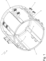
- Reference number 1 in Figure 1 indicates, as a whole, a blank feeding drum of an automatic machine (not shown) for making cigarette packets.
- the feeding drum 1 comprises two bases 2 with a circular shape, which are joined to each other by a plurality of axially arranged support elements 3. Each support element 3 is coupled to a corresponding transport bar 4 which is provided with (at least) two sucking holding heads 5.
- the rotation of the feeding drum 1 around a central rotation axis cyclically causes each transport bar 4 to pass through a loading station, where the two sucking holding heads 5 pick up a blank from the bottom of a hopper, and an unloading station, where the two sucking holding heads 5 release the blank.
- each transport bar 4 is coupled to the respective support element 3 by a dovetail interlock which extends axially (i.e., parallel to the axis of rotation of the feeding drum 1).
- each support element 3 has a trapezoidal-shaped recess 6, and each transport bar 4 has a trapezoidal-shaped projection 7 reproducing the shape of the recess 6 in order to engage the recess 6 (as far as possible) without gaps.
- the interlocking between each support element 3 and the respective transport bar 4 comprises joining the support element 3 and the transport bar 4 by inserting the projection 7 of the transport bar 4 into the recess 6 of the support element 3.
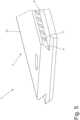
- Each transport bar 4 has a main wall 8 from which the trapezoidal-shaped projection 7 (in particular in the shape of an isosceles trapezium, i.e., a dovetail) rises cantilevered, which has two side walls 9 inclined relative to one another and a central base wall 10 interposed between the two side walls 9.
- the trapezoidal-shaped projection 7 in particular in the shape of an isosceles trapezium, i.e., a dovetail
- the two side walls 9 and the base wall 10 of the projection 7 define the interlocking surfaces, as they allow the transport bar 4 to be interlocked to a respective support element 3 (i.e., to another component of the feeding drum 1) upon their contact with the corresponding surfaces of the recess 6 obtained in the support element 3.
- a transport bar 4 (which is the male part of the interlock) is provided with the trapezoidal projection 7, and a support element 3 (which is the female part of the interlock) must have the recess 6, the shape of which is perfectly complementary to the shape of the projection 7, and the contact between the two interlocked components (i.e., the transport bar 4 and the support element 3) is established on the oblique side walls 9 and on the base wall 10 of the projection 7.
- each transport bar 4 has a plurality of protuberances 11, which rise cantilevered from both inclined side walls 9 of the projection 7 and are arranged at regular intervals from one another; in other words, on each inclined side wall 9 the protuberances 11 form an equally spaced row parallel to a sliding direction along which the projection 7 progressively enters the recess 6.
- each protuberance 11 is sized to have a certain degree of interference with the respective inner wall of the recess 6 and therefore must deform (plastically and/or elastically) to be able to enter the recess 6.
- the insertion of the projection 7 of a support bar 4 into the recess 6 of a support element 3 may also result in a removal - at least partial - of one or more protuberances 11 (i.e., one or more protuberances 11 in addition to deforming also experience at least a partial loss of material).
- the dovetail projection 7 is provided with a plurality of protuberances 11 on both inclined side walls 9.
- the protuberances 11 are also or only located on the base wall 10 of the dovetail projection 7 or on only one of the inclined side walls 9 of the dovetail projection 7.
- the protuberances 11 are also or only located on the interlocking surfaces of the recess 6 of each support element 3.
- the protuberances 11 can be present on at least one of the interlocking surfaces of the component (the transport bar 4) having the projection 7 and/or of the component (the support element 3) having the recess 6.
- the protuberances 11 are made of the same material as the projection 7, i.e., as the transport bar 4, and are an integral part of the projection 7, i.e., of the transport bar 4; in other words, the protuberances 11 are an integral part, without gaps, of the projection 7, i.e., of the transport bar 4.
- each transport bar 4 (and therefore the protuberances 11 which are an integral part of the transport bar 4) is made of a different material having a lower hardness than a material making up each support element 3.
- the protuberances 11 are made of a material different from that of the projection 7, i.e., of the transport bar 4; in this embodiment, the material making up the protuberances 11 has a lower hardness than the material making up the projection 7, i.e., the transport bar 4.
- the hardness of a given material is defined as an empirical property that quantifies the ability of that material to resist a plastic (and therefore permanent) deformation, such as an incision, a penetration, or a scratch.
- a material can be plastically, i.e., permanently, deformed by another material having a higher hardness.
- each protuberance 11 has a spherical curvature (i.e., it has a partially spherical shape such as a hemispherical shape); according to other embodiments, not shown, each protuberance 11 has a different curvature than the spherical curvature, for example it may have an ellipsoid curvature (therefore a semi-ellipsoidal shape, for example) or a paraboloid curvature (therefore a semi-paraboloid shape, for example).
- the dovetail projection 7 of each support bar 4 is preferably (but not necessarily) provided with a flared lead-in edge 12 suitable for facilitating the insertion of the projection 7 into the recess 6 of a corresponding support element 3.
- the dovetail projection 7 of each support bar 4 only rises from a limited portion of the axial extension of the main wall 8, i.e., a (minority) part of the main wall 8 is left without the dovetail projection 7.
- the dovetail projection 7 of each support bar 4 rises from the entire axial extension of the main wall 8.
- the transport bar 4 enters the recess 6 in the support element 3 at the flared lead-in edge 12, which facilitates its insertion.
- the side walls 9 of the projection 4 do not come into contact with the side surfaces of the recess 6 of the support element 3, in particular, only the main wall 8 and the base wall 10 of the projection 7 are in contact with the corresponding surfaces of the recess 6 of the support element 3.
- this first lead-in step only involves the sliding of the main wall 8 and the base wall 10 of the projection 7 on the corresponding surfaces of the recess 6.
- the second interlock sliding step begins when the flared lead-in edge 12 of the projection 7 ends. This step involves the sliding of all the walls 9 and 10 of the projection and the main wall 8 of the transport bar 4 on the corresponding surfaces of the recess 6 of the support element 3.
- a head wall of the support bar 4 is abutted against a stop provided in the recess 6 of the support element 3.
- the first lead-in step is omitted, and the interlocking is achieved by performing the second sliding step and the third stopping step.
- the recess 6 has no stop, and the interlocking is achieved by performing the second sliding step alone (and optionally the first lead-in step).
- the second sliding step is the feature for the interlocking between the two components (the transport bar 4 and the support element 3) that ensures the reliability of the joint.
- the transport bars 4 are made by additive manufacturing (3D printing) which allows objects (finished or semi-finished products) to be created by adding successive layers of material.
- the support elements 3 and therefore also the bases 2) that are devoid of the protuberances 11 can be made by traditional production methods (casting and/or machining with chip removal) or can be made through additive manufacturing (3D printing).
- the component on which to make the protuberances 11 is selected based on the technology chosen for the production of the interlocking components.
- the protuberances 11 shall be provided thereon. If, considering two components to be interlocked to each other, both components are made by additive manufacturing, then the component made of the material with the lowest hardness shall be provided with the protuberances 11. In other words, the protuberances 11 are provided on only one of either of the two components of the interlock, whether provided with the recess 6 or the projection 7, provided that this component is made of a material that is less hard than the other and made by additive manufacturing. According to a further embodiment, not shown, the protuberances 11 could be present on both components of the interlock.
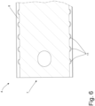
- Figure 5 shows a detail of a transport bar 4, specifically a side wall 9 provided with the protuberances 11.
- protuberances 11 which are arranged on the side walls 9 of the projection 7 and are equidistant from one another.
- the protuberances 11 are aligned along the direction in which the two components slide relative to each other when they interlock.
- the protuberances 11 on the side walls 9 of the projection 7 are plastically (or, at least partly, elastically) deformed, the material of the transport bar 4 having a lower hardness than the material of the support element 3.
- the protuberances 11 being aligned along the direction in which the two components slide relative to each other when they interlock, during the second interlock sliding step, the protuberances 11 are deformed one at a time, thereby facilitating the insertion of the projection 7 into the recess 6.
- the component made by additive manufacturing may also have a single protuberance 11, or multiple protuberances arranged at different distances from one another, in particular not aligned with one another.
- protuberances 11 which are not aligned with each other in the direction of sliding of the components can make it difficult to interlock the components, in particular by increasing the sliding resistance due to high interference of the protuberances 11 of the projection 7 with the respective surface of the recess 6. Nevertheless, this embodiment still allows the advantages of the method described above for the interlocking of two components.
- each protuberance 11 has a substantially spherical curvature.
- the surface of the protuberance 11 may have a different curvature from the spherical curvature.
- the protuberances 11 may have different thicknesses.
- the thickness is defined as the maximum height of a protuberance 11 relative to the surface from which it rises.
- the protuberances 11 may be of increasing thickness from the flared lead-in edge 12 so as to facilitate the insertion of the projection 7 into the recess 6.
- the protuberances 11 are made of the same material as the transport bar 4 made by additive manufacturing. It follows that the protuberances 11 are provided in the virtual 3D model of the component supplied to the additive manufacturing machine and produced at the same time as the component manufacturing process. In a different embodiment, the protuberances 11 are made of a different material and produced at the same time as the component manufacturing process by changing the material, or by using additive manufacturing machines capable of using multiple materials during a single manufacturing process.
- the manufacturing of the feeding drum 1 involves manufacturing each support element 3 with the respective recess 6, manufacturing each transport bar 4 with the respective projection 7 reproducing the shape of the recesses, and then joining each transport bar 4 to the corresponding support element 3 by inserting the projection 7 of the transport bar 4 into the recess 6 of the support element 3.
- the interlock between each transport bar 4 and the corresponding support element 3 is shaped like a dovetail to obtain a solid joint suitable to withstand continuous stresses because its trapezoidal shape maximizes the contact surfaces between the recess 6 and the projection 7, and it is also particularly difficult to separate the two components once they are interlocked.
- the recess 6 and the projection 7 have a different shape, for example a rectangular shape.
- the two components that are interlocked are a transport bar 4 and a support element 3 of a blank feeding drum 1, but the same type of interlocking can also be advantageously used for other types of components, made (at least one or both) through additive manufacturing, of any type of automatic machine (i.e., any class of products).
- any type of automatic machine i.e., any class of products.
- the above-described interlocking of two components may be applied in automatic machines for manufacturing and packing articles for a plant, a construction, a product for example, but not only, in the tobacco, pharmaceutical, food or entertainment sector; more generally, the above-described interlocking of two components may be applied when joining two components of a machine of any type.
- the embodiments described herein may be combined with each other without departing from the scope of protection of the present invention.
- the method described above for interlocking two components has many advantages. First of all, the method described above for interlocking two components allows a zero-gap interlocking when at least one of the two components is made by additive manufacturing.
- the components must be machined with high precision, particularly on the interlocking surfaces, to ensure zero gaps between the components.
- the dimensional accuracy that ensures the coupling accuracy is achieved with manual or numerically controlled machine tools.
- the two components thus interlocked do not have the possibility to move relative to each other, thereby ensuring reliability of the operations carried out with the automatic machine in question.
- the method described above for interlocking two components avoids post-production subtractive technology machining of the components made by additive manufacturing with the aim of obtaining accuracies suitable for achieving an effective interlocking between the components.
- the method described above for interlocking two components reduces the processing waste material, by using additive manufacturing only, thereby reducing the costs related to the production materials.
- the method described above for interlocking two components allows the process for manufacturing the component made by additive manufacturing to be repeatable on different machines operating through the same technology, thereby avoiding the increase in production costs and times.
Landscapes
- Engineering & Computer Science (AREA)
- General Engineering & Computer Science (AREA)
- Mechanical Engineering (AREA)
- Chemical & Material Sciences (AREA)
- Manufacturing & Machinery (AREA)
- Materials Engineering (AREA)
Applications Claiming Priority (1)
| Application Number | Priority Date | Filing Date | Title |
|---|---|---|---|
| IT202300000792 | 2023-01-20 |
Publications (1)
| Publication Number | Publication Date |
|---|---|
| EP4403781A1 true EP4403781A1 (de) | 2024-07-24 |
Family
ID=85792570
Family Applications (1)
| Application Number | Title | Priority Date | Filing Date |
|---|---|---|---|
| EP23220267.1A Pending EP4403781A1 (de) | 2023-01-20 | 2023-12-27 | Verfahren zum verriegeln zweier komponenten einer automatischen maschine zur herstellung oder verpackung von verbrauchsartikeln |
Country Status (1)
| Country | Link |
|---|---|
| EP (1) | EP4403781A1 (de) |
Citations (3)
| Publication number | Priority date | Publication date | Assignee | Title |
|---|---|---|---|---|
| DE3034360C2 (de) * | 1979-09-24 | 1993-11-18 | Secr Defence Brit | Verbrennbare Treibladungshülse |
| CN102917616A (zh) * | 2010-06-03 | 2013-02-06 | 尤尼林有限公司 | 组合元件和与之一起应用的转角连接 |
| IT202000029408A1 (it) * | 2020-12-02 | 2022-06-02 | Gd Spa | Macchina operatrice per la lavorazione di articoli da fumo con un componente elastico realizzato mediante manifattura additiva |
-
2023
- 2023-12-27 EP EP23220267.1A patent/EP4403781A1/de active Pending
Patent Citations (3)
| Publication number | Priority date | Publication date | Assignee | Title |
|---|---|---|---|---|
| DE3034360C2 (de) * | 1979-09-24 | 1993-11-18 | Secr Defence Brit | Verbrennbare Treibladungshülse |
| CN102917616A (zh) * | 2010-06-03 | 2013-02-06 | 尤尼林有限公司 | 组合元件和与之一起应用的转角连接 |
| IT202000029408A1 (it) * | 2020-12-02 | 2022-06-02 | Gd Spa | Macchina operatrice per la lavorazione di articoli da fumo con un componente elastico realizzato mediante manifattura additiva |
Similar Documents
| Publication | Publication Date | Title |
|---|---|---|
| JP5442184B2 (ja) | 等速自在継手内輪、その製造装置、その製造方法 | |
| EP3168023A1 (de) | Werkzeug und verfahren zum formen eines dreidimensionalen artikels oder behälters | |
| Thompson et al. | Process chain modeling and selection in an additive manufacturing context | |
| EP3527864B1 (de) | Verfahren zur herstellung eines ventils oder eines elements zur herstellung eines ventils | |
| JP6979055B2 (ja) | 超硬合金プレス成形品の製造のための方法および装置ならびに超硬合金プレス成形品 | |
| JP5373378B2 (ja) | 鍛造加工方法 | |
| EP4403781A1 (de) | Verfahren zum verriegeln zweier komponenten einer automatischen maschine zur herstellung oder verpackung von verbrauchsartikeln | |
| JP4418226B2 (ja) | 多数部片摩擦材料を有するクラッチ板を製造する方法及び装置 | |
| WO2018093546A1 (en) | Methods and spoke supports for additive manufacturing | |
| JP2014500396A (ja) | 成形アプリケーション用の粉末金属の軸方向及び径方向の保持部 | |
| JP2010131613A5 (de) | ||
| US20200376548A1 (en) | Compacting device and method for producing a cutting insert green body by compacting a powder | |
| JP4219400B2 (ja) | 異形積層コアの製造方法 | |
| US20140238097A1 (en) | Laminated cavity tooling | |
| KR100965306B1 (ko) | 티슬롯볼트 제작용 단조 금형 | |
| KR100906792B1 (ko) | 스터드 및 그 제조방법 | |
| JP2006223022A (ja) | リングコアの製造方法 | |
| KR101642348B1 (ko) | 드로잉 가공용 프로그레시브 금형 | |
| CN103167917B (zh) | 以较短工作周期制造至少部分闭合的空心型材的装置和方法 | |
| US3633260A (en) | Method of forming a spacer-expander | |
| JP3583614B2 (ja) | 歯車の製造方法 | |
| US7625522B2 (en) | Method and apparatus for forming a hole or slot in powder metal components | |
| JP4906676B2 (ja) | カムロブの成形方法 | |
| WO2017150289A1 (ja) | 樹脂接合品及びその製造方法 | |
| JP2009106952A5 (de) |
Legal Events
| Date | Code | Title | Description |
|---|---|---|---|
| PUAI | Public reference made under article 153(3) epc to a published international application that has entered the european phase |
Free format text: ORIGINAL CODE: 0009012 |
|
| STAA | Information on the status of an ep patent application or granted ep patent |
Free format text: STATUS: THE APPLICATION HAS BEEN PUBLISHED |
|
| AK | Designated contracting states |
Kind code of ref document: A1 Designated state(s): AL AT BE BG CH CY CZ DE DK EE ES FI FR GB GR HR HU IE IS IT LI LT LU LV MC ME MK MT NL NO PL PT RO RS SE SI SK SM TR |
|
| STAA | Information on the status of an ep patent application or granted ep patent |
Free format text: STATUS: REQUEST FOR EXAMINATION WAS MADE |
|
| 17P | Request for examination filed |
Effective date: 20250124 |
|
| GRAP | Despatch of communication of intention to grant a patent |
Free format text: ORIGINAL CODE: EPIDOSNIGR1 |
|
| STAA | Information on the status of an ep patent application or granted ep patent |
Free format text: STATUS: GRANT OF PATENT IS INTENDED |
|
| INTG | Intention to grant announced |
Effective date: 20260202 |