EP4403619A2 - Elektrochemisches detektionsverfahren für katalysatorreaktionsprodukt, elektrochemische detektionsvorrichtung und wandler - Google Patents
Elektrochemisches detektionsverfahren für katalysatorreaktionsprodukt, elektrochemische detektionsvorrichtung und wandler Download PDFInfo
- Publication number
- EP4403619A2 EP4403619A2 EP24181195.9A EP24181195A EP4403619A2 EP 4403619 A2 EP4403619 A2 EP 4403619A2 EP 24181195 A EP24181195 A EP 24181195A EP 4403619 A2 EP4403619 A2 EP 4403619A2
- Authority
- EP
- European Patent Office
- Prior art keywords
- liquid
- lump
- retaining structure
- catalytic reaction
- reaction product
- Prior art date
- Legal status (The legal status is an assumption and is not a legal conclusion. Google has not performed a legal analysis and makes no representation as to the accuracy of the status listed.)
- Pending
Links
Images



Classifications
-
- G—PHYSICS
- G01—MEASURING; TESTING
- G01N—INVESTIGATING OR ANALYSING MATERIALS BY DETERMINING THEIR CHEMICAL OR PHYSICAL PROPERTIES
- G01N27/00—Investigating or analysing materials by the use of electric, electrochemical, or magnetic means
- G01N27/26—Investigating or analysing materials by the use of electric, electrochemical, or magnetic means by investigating electrochemical variables; by using electrolysis or electrophoresis
- G01N27/403—Cells and electrode assemblies
- G01N27/406—Cells and probes with solid electrolytes
-
- G—PHYSICS
- G01—MEASURING; TESTING
- G01N—INVESTIGATING OR ANALYSING MATERIALS BY DETERMINING THEIR CHEMICAL OR PHYSICAL PROPERTIES
- G01N27/00—Investigating or analysing materials by the use of electric, electrochemical, or magnetic means
- G01N27/26—Investigating or analysing materials by the use of electric, electrochemical, or magnetic means by investigating electrochemical variables; by using electrolysis or electrophoresis
- G01N27/416—Systems
- G01N27/49—Systems involving the determination of the current at a single specific value, or small range of values, of applied voltage for producing selective measurement of one or more particular ionic species
-
- G—PHYSICS
- G01—MEASURING; TESTING
- G01N—INVESTIGATING OR ANALYSING MATERIALS BY DETERMINING THEIR CHEMICAL OR PHYSICAL PROPERTIES
- G01N27/00—Investigating or analysing materials by the use of electric, electrochemical, or magnetic means
- G01N27/26—Investigating or analysing materials by the use of electric, electrochemical, or magnetic means by investigating electrochemical variables; by using electrolysis or electrophoresis
- G01N27/27—Association of two or more measuring systems or cells, each measuring a different parameter, where the measurement results may be either used independently, the systems or cells being physically associated, or combined to produce a value for a further parameter
-
- G—PHYSICS
- G01—MEASURING; TESTING
- G01N—INVESTIGATING OR ANALYSING MATERIALS BY DETERMINING THEIR CHEMICAL OR PHYSICAL PROPERTIES
- G01N33/00—Investigating or analysing materials by specific methods not covered by groups G01N1/00 - G01N31/00
- G01N33/48—Biological material, e.g. blood, urine; Haemocytometers
- G01N33/50—Chemical analysis of biological material, e.g. blood, urine; Testing involving biospecific ligand binding methods; Immunological testing
- G01N33/53—Immunoassay; Biospecific binding assay; Materials therefor
- G01N33/557—Immunoassay; Biospecific binding assay; Materials therefor using kinetic measurement, i.e. time rate of progress of an antigen-antibody interaction
-
- C—CHEMISTRY; METALLURGY
- C12—BIOCHEMISTRY; BEER; SPIRITS; WINE; VINEGAR; MICROBIOLOGY; ENZYMOLOGY; MUTATION OR GENETIC ENGINEERING
- C12Q—MEASURING OR TESTING PROCESSES INVOLVING ENZYMES, NUCLEIC ACIDS OR MICROORGANISMS; COMPOSITIONS OR TEST PAPERS THEREFOR; PROCESSES OF PREPARING SUCH COMPOSITIONS; CONDITION-RESPONSIVE CONTROL IN MICROBIOLOGICAL OR ENZYMOLOGICAL PROCESSES
- C12Q1/00—Measuring or testing processes involving enzymes, nucleic acids or microorganisms; Compositions therefor; Processes of preparing such compositions
- C12Q1/001—Enzyme electrodes
Definitions
- the present invention relates to a technique for electrochemically detecting a product generated by progress of a catalytic reaction in a solution and dissolved in the solution.
- Detection sensitivity of a catalytic reaction product generated by catalytic reaction such as enzyme reaction and dissolved in a solution depends on the concentration of the product in the solution. In order to improve the concentration of the product in the solution, for example, longer catalytic reaction time is preferable or a smaller volume of the solution is preferable.
- Patent literature 1 and Non-patent literature 1 disclose a configuration that can prevent a solution from evaporating.
- Patent literature 1 discloses, as a technique related to ELISA (Enzyme-Linked ImmunoSorbent Assay), a configuration in which droplets of a hydrophilic solvent, which is an enzyme reaction field, are placed in a storage part (well) and the storage part is sealed with a hydrophobic solvent.
- ELISA Enzyme-Linked ImmunoSorbent Assay
- Non-patent literature 1 discloses a configuration in which a pattern of hydrophilic region is formed by forming a hydrophobic region on a hydrophilic surface, and droplets located on the pattern of hydrophilic region (that is, the enzyme reaction field) are covered with oil.
- Patent literature 1 International Publication No. WO2012/121310
- Non-patent literature 1 S. Sakakihara et al., "A Single-molecule enzymatic assay in a directly accessible femtoliter droplet array", Lab Chip, 2010, 10, 3355-3362
- evaporation of the solution can be prevented by covering a solution, which is a catalytic reaction field, with a liquid which is different from the solution. It is thereby possible to avoid a problem of evaporation causing a decrease in the volume of the solution and making detection impossible.
- the state in which the solution is covered with a liquid needs to be maintained stably and appropriately in a progression process of a catalytic reaction and in a process of detecting a catalytic reaction product.
- a situation occurs in which a liquid-liquid interface between the solution and the liquid is disturbed or the shape of the solution is changed considerably by application of vibration or shock, the progression of the catalytic reaction or detection processing is thereby affected, resulting in deterioration of detection accuracy or detection errors.
- vibration or shock may cause part of the solution to spill out of the well or the liquid may flow into the well.
- the technique disclosed here is an electrochemical detection technique to which the technique that a first lump of liquid, where a catalytic reaction progresses, is covered with a second lump of liquid is applied.
- the technique uses a liquid bath that contains a working electrode, a counter electrode, a first lump of liquid and a second lump of liquid.
- the first lump of liquid has conductivity.
- the working electrode is located in the first lump of liquid.
- the first lump of liquid is held to a liquid-retaining structure that allows the first lump of liquid to permeate and can retain the first lump of liquid.
- the liquid-retaining structure is located in the vicinity of the working electrode.
- the second lump of liquid has conductivity.
- the first lump of liquid and the second lump of liquid form a liquid-liquid interface and the catalytic reaction product is insoluble in the second lump of liquid.
- the counter electrode is located in the second lump of liquid.
- the liquid-retaining structure stably and appropriately maintains the state in which the first lump of liquid is covered with the second lump of liquid, it is possible to stably detect a catalytic reaction product with high sensitivity.
- electrochemically detected is a product generated by progress of a catalytic reaction in a first lump of liquid (that is, a lump of solution, which is a catalytic reaction field) and dissolved in the first lump of liquid.
- Fig. 1 schematically shows a configuration example of a detection apparatus 1 of the present embodiment.
- the detection apparatus 1 includes a liquid bath 10, a working electrode 40, a counter electrode 50, a reference electrode 60 and a potentiostat 80.
- the liquid bath 10 contains a first lump of liquid 20 and a second lump of liquid 30.
- the first lump of liquid 20 and the second lump of liquid 30 form a liquid-liquid interface (that is, an interface between two liquids).
- the first lump of liquid 20 is placed on a bottom surface 11 of the liquid bath 10 and is covered with the second lump of liquid 30.
- the working electrode 40 is located at the bottom surface 11 of the liquid bath 10 and covered with the first lump of liquid 20. That is, the working electrode 40 is in contact with the first lump of liquid 20, whereas it is not in contact with the second lump of liquid 30.
- the counter electrode 50 and the reference electrode 60 are placed in the second lump of liquid 30 and are electrically connected to the working electrode 40 via the liquid-liquid interface between the first lump of liquid 20 and the second lump of liquid 30.
- reference numeral 70 denotes a salt bridge.
- the working electrode 40, the counter electrode 50 and the reference electrode 60 are connected to the potentiostat 80 in this example.
- the potentiostat 80 functions as a constant-voltage power-supply apparatus and includes a variable power supply 81, a voltmeter 82 and an ammeter 83.
- the catalytic reaction product is confined in the first lump of liquid 20 and is not dissolved in the second lump of liquid 30 (that is, the product does not move from the first lump of liquid 20 to the second lump of liquid 30).
- An oxidation reduction reaction between the catalytic reaction product and the working electrode 40 causes a current to flow through the working electrode 40. By detecting this current, the catalytic reaction product is detected or a quantitative analysis is performed.
- Fig. 1 illustrates only one working electrode 40
- two or more working electrodes 40 arranged, for example, in an array are generally installed at a substrate and the substrate is located on the bottom surface 11 of the liquid bath 10.
- the detection apparatus 1 includes two or more working electrodes 40
- the detection apparatus 1 includes two or more first lumps of liquid 20.
- Each of the two or more working electrodes 40 is covered with the corresponding one of the two or more first lumps of liquid 20.
- the first lumps of liquid 20 are independent of each other and the first lumps of liquid 20, which are different from each other, are separated by the second lump of liquid 30.
- the second lump of liquid 30 is a single liquid lump.
- the second lump of liquid 30 and any one of the two or more first lumps of liquid 20 form a liquid-liquid interface.
- Each of the two or more first lumps of liquid 20 is covered with the second lump of liquid 30.
- an antigen-antibody complex is detected or quantitative analysis is performed, for example, by labeling an antigen or antibody (that is, immunoglobulin) contained in a sample with an enzyme and detecting a product obtained by a reaction between the enzyme and a substrate.
- an antigen or antibody that is, immunoglobulin
- the following operation is performed in a combination of a sandwich ELISA (sandwich ELISA protocol) and an electrochemical detection method.
- operation such as cleaning, incubation (leaving a product at a constant temperature) is not specified.
- the second lump of liquid 30 is insoluble in the conductive first lump of liquid 20, and is a conductive liquid.
- the first lump of liquid 20 is generally an aqueous solution having a buffering ability, and thus the second lump of liquid 30 is, for example, an organic solvent that is insoluble in water and can dissolve a support electrolyte that is for conductivity.
- the organic solvent is preferably a liquid that can be easily handled as a solvent for electrochemical detection, in other words, preferably, the organic solvent is a liquid at ordinary temperature and has low reactivity against water and electrode materials (such as, gold, platinum) within a detection potential range.
- nitrobenzene, 1,2-dichlorobenzene, 1-nitro-2-(n-octyloxy) benzene, 1,2-dichloroethane, 1,4-dichlorobutane, 1,6-dichlorohexane, 1-octanol or 1,9-decadiene is suitable for the organic solvent.
- the support electrolyte As the support electrolyte that is soluble in these organic solvents and can impart conductivity to the organic solvents, a support electrolyte used for electrochemical detection in a common non-aqueous solution may be adopted.
- the support electrolyte is preferably a salt containing, as its anion, any one of chloride ion, bromide ion, iodide ion, sulfate ion, nitrate ion, hyperchloric acid ion, tetrafluoroboric acid ion, hexafluorophosphoric acid ion and sulfonic acid ion, and, as its cation, any one of lithium ion, sodium ion, potassium ion, rubidium ion, cesium ion, ammonium ion and tetraalkyl ammonium ion having alkyl groups of arbitrary chain lengths.
- a combination of the labeling enzyme and the substrate is a combination having electrochemical activity and capable of generating a product soluble in the first lump of liquid 20 and not soluble in the second lump of liquid 30.
- the first lump of liquid 20 is an aqueous solution
- the second lump of liquid 30 is the aforementioned organic solvent
- a combination of, for example, alkaline phosphatase and phosphoric acid 4-aminophenyl ester or a combination of, for example, horseradish peroxidase and potassium ferricyanide is suitable for a combination of the labeling enzyme and the substrate.
- the liquid-retaining structure to stably and appropriately maintain the state in which the first lump of liquid 20 is covered with the second lump of liquid 30 will be described.
- the liquid liquid-retaining structure is formed before step (1).
- the liquid liquid-retaining structure will simply be referred to as a "retaining structure.”
- the retaining structure allows the first lump of liquid 20 to permeate and can also retain the first lump of liquid 20.
- the retaining structure is, for example, a porous body having a hydrophilic surface (in this regard, the "surface” is an air-contacting part when the retaining structure is placed in the air, and the inner surface of pores is also included) or dry gel formed by a polymer that forms hydrogels when moistened with water.
- the retaining structure is placed at a place in the liquid bath 10 where the first lump of liquid 20 is located, that is, in a local space facing the working electrode 40.
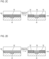
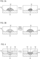
- Fig. 2 and Fig. 3 show several examples of the retaining structure. From the standpoint of easy-to-understand illustration, only one working electrode 40 is shown in Fig. 2 and Fig. 3 and the working electrode 40 has a circular surface shape in this example.
- reference numeral 100 denotes a substrate at which the working electrode 40 is installed.
- a retaining structure 91 is a porous body.
- the material of the porous body include materials made of an organic polymer such as cellulose having a pore diameter of on the order of 0.1 to 10 ⁇ m, nitrocellulose, acetylcellulose and polyvinylidene difluoride that has been appropriately subjected to a hydrophilic treatment or include inorganic materials such as silica, silicon and alumina (silicon dioxide).
- the retaining structure 91 which is a porous body of the organic polymer, is formed by dissolving the polymer as a raw material in an appropriate solvent, placing the solution 91' on the working electrode 40 using a technique such as spotting, screen printing and inkjet printing, and then drying the solvent.
- the solvent contains an appropriate cross-linking agent if necessary.
- the retaining structure 91 which is a porous body of nitrocellulose, is formed by dropping, onto the working electrode 40, droplets of the solution 91' obtained by dissolving nitrocellulose in a methyl isobutyl ketone (4-methyl-2-pentanone) solvent using a micropipette, and then removing the solvent by natural drying.
- the retaining structure 91 which is a porous body of an inorganic material, is formed using, for example, a technique of forming porous silica on the working electrode 40 by a sol-gel method or a technique of forming porous silicon or porous alumina on the working electrode 40 by an anode oxidation method.
- a retaining structure 92 is a porous body.
- the above-described porous body is formed in advance as a small block 92' and the small block 92' are pasted onto the working electrode 40 as the retaining structure 92.
- a porous body is formed in the form of a sheet on the substrate 100 where the working electrode 40 is located, using a technique such as spin coating.
- the porous body is impregnated with resin, which is insoluble in both of the first lump of liquid 20 and the second lump of liquid 30, to form a resin-impregnated sheet-like porous body 93 in which all the pores are filled with the resin.
- resin which is insoluble in both of the first lump of liquid 20 and the second lump of liquid 30, to form a resin-impregnated sheet-like porous body 93 in which all the pores are filled with the resin.
- only the resin on the working electrode 40 is selectively removed by an appropriate solvent.
- a retaining structure 94 which is a porous body, is formed.
- a sheet-like porous body is formed by, for example, coating the substrate 100, which the working electrode 40 is located at, by spin coating with a solution resulting from dissolving nitrocellulose in a methyl isobutyl ketone solvent, and then removing the solvent by natural drying. Furthermore, negative photosensitive resin is dropped onto the porous body to impregnate the porous body with the photosensitive resin. By selectively removing only the photosensitive resin on the working electrode 40 by photolithography, the retaining structure 94, which is a porous body, is formed.
- the retaining structure 94 is formed by selectively impregnating the region other than the working electrode 40 of the sheet-like porous body 93' described in the third example with resin insoluble in both of the first lump of liquid 20 and the second lump of liquid 30, using a technique such as spotting, screen printing and inkjet printing.
- reference numeral 93 denotes the resin-impregnated sheet-like porous body.
- the porous body can be formed by agglomerated minute particles.
- a retaining structure 95 which is a porous body, is formed by, for example, agglomerating on the working electrode 40 minute particles such as polystyrene minute particles each having a diameter of on the order of 0.1 to 10 ⁇ m, silica minute particles, alumina minute particles, magnetic minute particles used for protein separation and refining or the like or agarose minute particles used as carriers for an affinity column.
- binder molecules for binding minute particles together can be used to agglomerate the minute particles.
- a retaining structure 95 which is an agglomerate of minute particles, is formed by suspending the binder molecules and the minute particles in an appropriate solvent, dropping droplets of a suspension 95' onto the working electrode 40, and then drying the solvent.
- molecules, a binding process by which progresses by an operation such as heating or light irradiation, are used as the binder molecules, the operation are executed before or after drying the solvent.
- Minute particles may be agglomerated on the working electrode 40 to which a DC voltage or AC voltage is applied, using an electrophoretic force or dielectrophoretic force produced thereby.
- a retaining structure 96 is formed by a polymer that forms hydrogels by absorption of water.
- the polymer that forms hydrogels by absorption of water include polyacrylic amide (poly(2-propenamide)), agarose, sodium alginate or collagen.
- a solution 96' of the polymer which is a raw material, dissolved in an appropriate solvent, using a technique such as spotting, screen printing or inkjet printing, and then drying the solvent, the retaining structure 96, which is dry gel, is formed.
- the solvent may contain an appropriate cross-linking agent if necessary.
- Collagen hydrogels are obtained by, for example, dropping droplets of the solution 96', which is obtained by dissolving collagen as a polymer and glutalaldehyde (1,5-pentanedial) as a cross-linking agent in a phosphoric acid buffer solution, onto the working electrode 40 using a micropipette, and then causing a cross-linking reaction to progress at a room temperature.
- the retaining structure 96 is formed by allowing the hydrogels to dry naturally.
- Fig. 4 shows an example in which a well 105 is formed at the substrate 100 located on the bottom surface 11 of the liquid bath 10.
- the working electrode 40 is located in the well 105.
- the well 105 is formed by placing hydrophobic resin, which is insoluble in both of the first lump of liquid 20 and the second lump of liquid 30, on the substrate 100 using a technique such as photolithography or screen printing.
- Reference numeral 106 in Fig. 4 denotes a layer of hardened resin.
- Fig. 4 shows an example in which a retaining structure 91 is formed by drying the solution 91' of a polymer. The solution 91' is dropped into the well 105. As a result, the retaining structure 91 is placed in the well 105.
- the retaining structure 91, 92, 94, 95 and 96 are generically called “retaining structure 90." Placing on the working electrode 40 the retaining structure 90, which allows the first lump of liquid 20 to permeate, can retain the first lump of liquid 20, and is insoluble in both of the first lump of liquid 20 and the second lump of liquid 30, strongly retains the first lump of liquid 20 on the working electrode 40.
- the retaining structure 90 is provided for each of working electrodes 40.
- a combination of the well 105 and the retaining structure 90 is provided for each of working electrodes 40.
- the second lump of liquid 30 is poured into the liquid bath 10. Progression of the enzyme reaction in ELISA and detection of the enzyme reaction product are performed for each working electrode 40 with the first lumps of liquid 20 retained to the retaining structures 90.
- the enzyme reactions corresponding to the working electrodes 40 proceed independently of each other, that is, any two of them do not affect each other.
- detections of the enzyme reaction products corresponding to the working electrodes 40 are performed independently of each other, that is, any two of them do not affect each other.
- the catalytic reaction product is detected electrochemically. Therefore, the retaining structure 90 capable of securing the substance diffusion and the conduction path such as a porous body or gel does not adversely affect the catalytic reaction field.
- ELISA uses an enzyme as a catalyst, but the catalyst is not limited to an enzyme.
- the catalyst may include metal catalyst, ribozyme, cells containing enzymes on the surface thereof or inside, organelle, minute particles that artificially adsorb or are artificially bound to these elements, and vesicle.
- the sandwich ELISA forms a composite of capture antibody, antigen, primary antibody and enzyme-labeled secondary antibody, and thereby causes the catalyst to be indirectly bound to the solid phase, but the catalyst binding method is not limited to this.
- the catalyst may be indirectly bound to the solid phase by hybridizing a probe DNA preliminarily bound to the solid phase surface with a single-strand DNA complementary with the probe DNA and labeled with the catalyst.
- the catalyst may be indirectly bound to the solid phase by making antigen, peptide or sugar chain, these being preliminarily bound to the surface of the solid phase, interact with an antibody or a lectin that can specifically bind to those molecules and are labeled with the catalyst.
- Such a binding method is already well known in expression analysis of using a DNA chip or a protein chip.
- the catalyst when measuring activity of the catalyst itself, the catalyst may be directly bound to the surface of the solid phase.
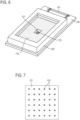
- the transducer of the present embodiment has a structure in which a liquid bath 120 that can contain a solution 110 is mounted on an LSI chip (large scale integrated chip) 130.
- the liquid bath 120 has a hole 121 at the center thereof and the LSI chip 130 is placed at lower end of the hole 121 and covers the hole 121.
- the LSI chip 130 and the liquid bath 120 are fixed to a substrate 140 and a wiring pattern 141 for connecting the LSI chip 130 to an external apparatus that controls the transducer is formed on the substrate 140.
- Reference numeral 150 in Fig. 5B denotes a bonding wire for connecting the LSI chip 130 to the wiring pattern 141.
- a sensor region 131 is formed on the top surface of the LSI chip 130.
- the sensor region 131 is located in the hole 121 at the bottom surface of the liquid bath 120.
- 400 electrodes 132 of ⁇ 40 ⁇ m that function as working electrodes are formed in the sensor region 131 in this example.
- the 400 electrodes 132 constitute a 20 ⁇ 20 array, and are arranged at intervals of 250 ⁇ m.
- Fig. 8 shows part of the sensor region 131 in which the electrodes 132 are formed.
- the material of the electrodes 132 is gold in this example and a silicon nitride film is formed on the top surface of the LSI chip 130 including at least the sensor region 131 except the electrodes 132.
- the LSI chip 130 has a function to detect currents generated by oxidation reduction reaction between each electrode 132 and an object to be detected, and amplify the respective detected currents.
- the LSI chip 130 in this example has a configuration in which the retaining structure 90 that allows an aqueous solution to permeate and can retain the aqueous solution is provided on each electrode 132 or a configuration in which the electrode 132 is located in each well 105 arranged in an array in the sensor region 131 and the retaining structure 90 is provided in each well 105. Therefore, the present transducer can strongly retain on each electrode 132 the first lump of liquid where a catalytic reaction takes place.
- the solution 110 is the second lump of liquid that covers the first lump of liquid and the first lump of liquid is not shown.
- a counter electrode 160 and a reference electrode 170 are not necessarily essential components of the transducer. The counter electrode 160 and the reference electrode 170 are introduced into the second lump of liquid before implementing the method of the present embodiment.
- connection means not necessarily deny the presence of one or more “interconnected” or “combined” or “coupled” intermediate elements unless otherwise specified.
- a method of electrochemically detecting a catalytic reaction product by confining the catalytic reaction product within a first lump of liquid and by using a working electrode disposed in the first lump of liquid and a counter electrode disposed in a second lump of liquid, the catalytic reaction product being generated by progress of a catalytic reaction in the first lump of liquid, the first lump of liquid and the second lump of liquid being contained in a liquid bath, and the second lump of liquid being in contact with the first lump of liquid to form a liquid-liquid interface, the method comprising:
- EEE2 The method according to EEE1, further comprising a preparation step of dropping the first lump of liquid on the retaining structure and then pouring the second lump of liquid into the liquid bath.
- EEE3 The method according to EEE1 or EEE2, wherein the retaining structure is made of a porous body having a hydrophilic surface.
- EEE4 The method according to EEE1 or EEE2, wherein the retaining structure is made of a polymer forming hydrogels by absorption of water.
- EEE5. The method according to any one of EEE1 to EEE4, wherein a catalyst is supported by the retaining structure.
- EEE6 The method according to any one of EEE1 to EEE5, wherein the retaining structure is placed in a well constructed on a bottom surface of the liquid bath.
- EEE7 The method according to any one of EEE1 to EEE5, wherein the working electrodes and the retaining structures respectively corresponding to the working electrodes are provided in the one liquid bath so as to allow the catalytic reactions to progress and detect the catalytic reaction products independently of one another.
- EEE8 The method according to EEE6, wherein the working electrodes, and the wells and the retaining structures respectively corresponding to the working electrodes are provided in the one liquid bath so as to allow the catalytic reactions to progress and detect the catalytic reaction products independently of one another.
- An apparatus capable of electrochemically detecting a catalytic reaction product generated by progress of a catalytic reaction in a first lump of liquid comprising:
- EEE10 The apparatus according to EEE9, wherein the retaining structure is made of a porous body having a hydrophilic surface.
- EEE11 The apparatus according to EEE9, wherein the retaining structure is made of a polymer forming hydrogels by absorption of water.
- EEE12 The apparatus according to any one of EEE9 to EEE11, wherein the retaining structure can support a catalyst.
- EEE13 The apparatus according to any one of EEE9 to EEE12, wherein a well is constructed on a bottom surface of the liquid bath, and the retaining structure is disposed in the well.
- EEE14 The apparatus according to any one of EEE9 to EEE12, wherein the working electrodes and the retaining structures respectively corresponding to the working electrodes are provided in the liquid bath.
- EEE15 The apparatus according to EEE13, wherein the working electrodes, and the wells and the retaining structures respectively corresponding to the working electrodes are provided in the liquid bath.
- a transducer for electrochemically detecting a catalytic reaction product generated by progress of a catalytic reaction in a solution comprising a structure with a liquid bath configured to contain the solution and mounted on an LSI chip, wherein
- EEE17 The transducer according to EEE16, wherein the retaining structure is made of a porous body having a hydrophilic surface.
- EEE18 The transducer according to EEE16, wherein the retaining structure is made of a polymer forming hydrogels by absorption of water.
- EEE19 The transducer according to any one of EEE16 to EEE18, wherein
Landscapes
- Health & Medical Sciences (AREA)
- Life Sciences & Earth Sciences (AREA)
- Chemical & Material Sciences (AREA)
- Immunology (AREA)
- Molecular Biology (AREA)
- Physics & Mathematics (AREA)
- Chemical Kinetics & Catalysis (AREA)
- Pathology (AREA)
- General Physics & Mathematics (AREA)
- General Health & Medical Sciences (AREA)
- Biochemistry (AREA)
- Analytical Chemistry (AREA)
- Engineering & Computer Science (AREA)
- Electrochemistry (AREA)
- Biomedical Technology (AREA)
- Urology & Nephrology (AREA)
- Hematology (AREA)
- Medicinal Chemistry (AREA)
- Food Science & Technology (AREA)
- Microbiology (AREA)
- Cell Biology (AREA)
- Biotechnology (AREA)
- Apparatus Associated With Microorganisms And Enzymes (AREA)
- Catalysts (AREA)
Applications Claiming Priority (3)
| Application Number | Priority Date | Filing Date | Title |
|---|---|---|---|
| JP2019110265A JP7201178B2 (ja) | 2019-06-13 | 2019-06-13 | 触媒反応生成物の電気化学的測定方法、電気化学測定装置及びトランスデューサ |
| PCT/JP2020/016080 WO2020250559A1 (ja) | 2019-06-13 | 2020-04-10 | 触媒反応の生成物の電気化学的検出方法、電気化学検出装置およびトランスデューサ |
| EP20822801.5A EP3985091B1 (de) | 2019-06-13 | 2020-04-10 | Elektrochemisches detektionsverfahren für katalytisches reaktionsprodukt und elektrochemische detektionsvorrichtung |
Related Parent Applications (2)
| Application Number | Title | Priority Date | Filing Date |
|---|---|---|---|
| EP20822801.5A Division EP3985091B1 (de) | 2019-06-13 | 2020-04-10 | Elektrochemisches detektionsverfahren für katalytisches reaktionsprodukt und elektrochemische detektionsvorrichtung |
| EP20822801.5A Division-Into EP3985091B1 (de) | 2019-06-13 | 2020-04-10 | Elektrochemisches detektionsverfahren für katalytisches reaktionsprodukt und elektrochemische detektionsvorrichtung |
Publications (2)
| Publication Number | Publication Date |
|---|---|
| EP4403619A2 true EP4403619A2 (de) | 2024-07-24 |
| EP4403619A3 EP4403619A3 (de) | 2024-11-27 |
Family
ID=73743370
Family Applications (2)
| Application Number | Title | Priority Date | Filing Date |
|---|---|---|---|
| EP24181195.9A Pending EP4403619A3 (de) | 2019-06-13 | 2020-04-10 | Elektrochemisches detektionsverfahren für katalysatorreaktionsprodukt, elektrochemische detektionsvorrichtung und wandler |
| EP20822801.5A Active EP3985091B1 (de) | 2019-06-13 | 2020-04-10 | Elektrochemisches detektionsverfahren für katalytisches reaktionsprodukt und elektrochemische detektionsvorrichtung |
Family Applications After (1)
| Application Number | Title | Priority Date | Filing Date |
|---|---|---|---|
| EP20822801.5A Active EP3985091B1 (de) | 2019-06-13 | 2020-04-10 | Elektrochemisches detektionsverfahren für katalytisches reaktionsprodukt und elektrochemische detektionsvorrichtung |
Country Status (6)
| Country | Link |
|---|---|
| US (1) | US12535462B2 (de) |
| EP (2) | EP4403619A3 (de) |
| JP (1) | JP7201178B2 (de) |
| CN (1) | CN113966385A (de) |
| TW (1) | TWI752483B (de) |
| WO (1) | WO2020250559A1 (de) |
Citations (1)
| Publication number | Priority date | Publication date | Assignee | Title |
|---|---|---|---|---|
| WO2012121310A1 (ja) | 2011-03-08 | 2012-09-13 | 独立行政法人科学技術振興機構 | ビーズ封入方法、ターゲット分子を検出する方法、アレイ、キット及びターゲット分子検出装置 |
Family Cites Families (20)
| Publication number | Priority date | Publication date | Assignee | Title |
|---|---|---|---|---|
| US5212050A (en) * | 1988-11-14 | 1993-05-18 | Mier Randall M | Method of forming a permselective layer |
| US7348183B2 (en) * | 2000-10-16 | 2008-03-25 | Board Of Trustees Of The University Of Arkansas | Self-contained microelectrochemical bioassay platforms and methods |
| JP2005227096A (ja) * | 2004-02-12 | 2005-08-25 | Suenaga Tomokazu | イムノアッセイ分析装置、チップ電極、および検査チップ |
| JP3930517B2 (ja) * | 2005-03-23 | 2007-06-13 | 株式会社東芝 | 生体分子の定量分析チップ、及び、定量分析方法、定量分析装置及びシステム |
| US8940143B2 (en) * | 2007-06-29 | 2015-01-27 | Intel Corporation | Gel-based bio chip for electrochemical synthesis and electrical detection of polymers |
| JP4933656B1 (ja) * | 2010-12-28 | 2012-05-16 | 日本航空電子工業株式会社 | 電気化学計測チップ用電極装置 |
| KR101532112B1 (ko) * | 2011-06-14 | 2015-06-26 | 삼성전기주식회사 | 바이오 칩 |
| JP5769020B2 (ja) * | 2011-10-25 | 2015-08-26 | 国立大学法人東北大学 | 複数の電極を備えたicチップ |
| JP6247064B2 (ja) * | 2013-09-20 | 2017-12-13 | 株式会社日立ハイテクノロジーズ | 生体分子計測装置 |
| US9513247B2 (en) * | 2014-02-27 | 2016-12-06 | Ams International Ag | Electrochemical sensor |
| RU2691694C2 (ru) * | 2014-07-08 | 2019-06-17 | Японское Агентство По Науке И Технике | Способ герметизации вещества |
| CA2973495C (en) * | 2015-02-20 | 2020-09-15 | Halliburton Energy Services, Inc. | Thin-layer spectroelectrochemical cell for use in subterranean formation operations |
| JP6116075B1 (ja) | 2015-11-20 | 2017-04-19 | 日本航空電子工業株式会社 | 電気化学測定方法、電気化学測定装置及びトランスデューサ |
| JP6086412B1 (ja) * | 2015-12-22 | 2017-03-01 | 日本航空電子工業株式会社 | 電気化学測定方法、電気化学測定装置及びトランスデューサ |
| JP6116080B1 (ja) * | 2016-04-26 | 2017-04-19 | 日本航空電子工業株式会社 | 電気化学測定方法、電気化学測定装置及びトランスデューサ |
| JP6344775B2 (ja) | 2016-05-20 | 2018-06-20 | 国立大学法人東北大学 | 電気化学イメージング方法、電気化学測定装置及びトランスデューサ |
| US20190277828A1 (en) | 2016-12-07 | 2019-09-12 | Panasonic Intellectual Property Management Co., Ltd. | Electrochemical measuring method and electrochemical measuring device |
| JP6380962B1 (ja) * | 2017-03-15 | 2018-08-29 | 国立大学法人東北大学 | ハイドロゲルの電気化学的な作製方法、細胞がパターニングされたハイドロゲルの作製方法、ハイドロゲル作製装置及びトランスデューサ |
| JP7212940B2 (ja) | 2017-03-29 | 2023-01-26 | 国立研究開発法人科学技術振興機構 | 微小物質検出方法及び微小物質検出用デバイス |
| JP7329851B2 (ja) | 2018-03-02 | 2023-08-21 | 国立研究開発法人科学技術振興機構 | 酵素反応生成物の検出方法 |
-
2019
- 2019-06-13 JP JP2019110265A patent/JP7201178B2/ja active Active
-
2020
- 2020-04-10 US US17/613,361 patent/US12535462B2/en active Active
- 2020-04-10 CN CN202080042214.9A patent/CN113966385A/zh active Pending
- 2020-04-10 EP EP24181195.9A patent/EP4403619A3/de active Pending
- 2020-04-10 WO PCT/JP2020/016080 patent/WO2020250559A1/ja not_active Ceased
- 2020-04-10 EP EP20822801.5A patent/EP3985091B1/de active Active
- 2020-05-04 TW TW109114770A patent/TWI752483B/zh active
Patent Citations (1)
| Publication number | Priority date | Publication date | Assignee | Title |
|---|---|---|---|---|
| WO2012121310A1 (ja) | 2011-03-08 | 2012-09-13 | 独立行政法人科学技術振興機構 | ビーズ封入方法、ターゲット分子を検出する方法、アレイ、キット及びターゲット分子検出装置 |
Non-Patent Citations (1)
| Title |
|---|
| S. SAKAKIHARA ET AL.: "A Single-molecule enzymatic assay in a directly accessible femtoliter droplet array", LAB CHIP, vol. 10, 2010, pages 3355 - 3362 |
Also Published As
| Publication number | Publication date |
|---|---|
| US20220221424A1 (en) | 2022-07-14 |
| TW202109041A (zh) | 2021-03-01 |
| EP3985091A4 (de) | 2022-09-28 |
| JP2020201211A (ja) | 2020-12-17 |
| EP3985091A1 (de) | 2022-04-20 |
| TWI752483B (zh) | 2022-01-11 |
| US12535462B2 (en) | 2026-01-27 |
| EP3985091B1 (de) | 2026-03-04 |
| EP4403619A3 (de) | 2024-11-27 |
| WO2020250559A1 (ja) | 2020-12-17 |
| JP7201178B2 (ja) | 2023-01-10 |
| CN113966385A (zh) | 2022-01-21 |
Similar Documents
| Publication | Publication Date | Title |
|---|---|---|
| JP4777659B2 (ja) | 集積化固相親水性マトリクス回路およびマイクロ・アレイ | |
| Wang et al. | New insights into the structure–performance relationships of mesoporous materials in analytical science | |
| Iqbal et al. | Advances in immobilized enzyme microbioreactors in capillary electrophoresis | |
| KR100635110B1 (ko) | 현장분석용 랩온어칩 및 랩온어칩용 신호탐지기 | |
| US20060141469A1 (en) | Multi-layered electrochemical microfluidic sensor comprising reagent on porous layer | |
| JP2000514184A (ja) | 電子ピペッタおよび電気泳動バイアスのための補償手段 | |
| US12535462B2 (en) | Electrochemical detection method for catalytic reaction product, electrochemical detection apparatus and transducer | |
| JP4699840B2 (ja) | バイオチップ及び免疫分析方法 | |
| KR20200001389A (ko) | 자성입자와 전기화학센서를 이용한 면역진단 바이오마커 검출 시스템 및 방법 | |
| JP4732913B2 (ja) | マイクロチップ及びマイクロチップの使用方法 | |
| Takao et al. | Direct measurement of initial rate of enzyme reaction by electrokinetic filtration using a hydrogel-plugged capillary device | |
| US7276369B2 (en) | Method for detecting a substance and microtiter plate | |
| CA2527660A1 (en) | Biochip devices for ion transport measurement, methods of manufacture, and methods of use | |
| EP3974513B1 (de) | Elektrochemisches nachweisverfahren für das produkt einer katalysierten reaktion | |
| KR100757348B1 (ko) | 극다공성 한천면역입자를 포함하는 미세유체소자 및 이를이용한 면역측정방법 | |
| EP1848988A2 (de) | Elektrochemisches wahrnehmungsverfahren | |
| CN121899401A (zh) | 一种集成功能化多孔膜的离心式微流控芯片及检测方法 | |
| Silva et al. | Bioinspired Chemically Modified Electrodes for Electroanalysis |
Legal Events
| Date | Code | Title | Description |
|---|---|---|---|
| PUAI | Public reference made under article 153(3) epc to a published international application that has entered the european phase |
Free format text: ORIGINAL CODE: 0009012 |
|
| STAA | Information on the status of an ep patent application or granted ep patent |
Free format text: STATUS: REQUEST FOR EXAMINATION WAS MADE |
|
| 17P | Request for examination filed |
Effective date: 20240610 |
|
| AC | Divisional application: reference to earlier application |
Ref document number: 3985091 Country of ref document: EP Kind code of ref document: P |
|
| AK | Designated contracting states |
Kind code of ref document: A2 Designated state(s): AL AT BE BG CH CY CZ DE DK EE ES FI FR GB GR HR HU IE IS IT LI LT LU LV MC MK MT NL NO PL PT RO RS SE SI SK SM TR |
|
| REG | Reference to a national code |
Ref country code: DE Ref legal event code: R079 Free format text: PREVIOUS MAIN CLASS: C12M0001340000 Ipc: G01N0027406000 |
|
| PUAL | Search report despatched |
Free format text: ORIGINAL CODE: 0009013 |
|
| RAP3 | Party data changed (applicant data changed or rights of an application transferred) |
Owner name: TOHOKU UNIVERSITY Owner name: JAPAN AVIATION ELECTRONICS INDUSTRY, LIMITED |
|
| AK | Designated contracting states |
Kind code of ref document: A3 Designated state(s): AL AT BE BG CH CY CZ DE DK EE ES FI FR GB GR HR HU IE IS IT LI LT LU LV MC MK MT NL NO PL PT RO RS SE SI SK SM TR |
|
| RIC1 | Information provided on ipc code assigned before grant |
Ipc: C12Q 1/00 20060101ALN20241022BHEP Ipc: G01N 27/406 20060101AFI20241022BHEP |
|
| STAA | Information on the status of an ep patent application or granted ep patent |
Free format text: STATUS: EXAMINATION IS IN PROGRESS |
|
| 17Q | First examination report despatched |
Effective date: 20250715 |
|
| GRAP | Despatch of communication of intention to grant a patent |
Free format text: ORIGINAL CODE: EPIDOSNIGR1 |
|
| STAA | Information on the status of an ep patent application or granted ep patent |
Free format text: STATUS: GRANT OF PATENT IS INTENDED |
|
| RIC1 | Information provided on ipc code assigned before grant |
Ipc: G01N 27/406 20060101AFI20260112BHEP Ipc: C12Q 1/00 20060101ALN20260112BHEP |
|
| INTG | Intention to grant announced |
Effective date: 20260129 |