EP4403296A2 - System zum verschweissen mehrerer rohlinge zu einem bauteil - Google Patents
System zum verschweissen mehrerer rohlinge zu einem bauteil Download PDFInfo
- Publication number
- EP4403296A2 EP4403296A2 EP24179952.7A EP24179952A EP4403296A2 EP 4403296 A2 EP4403296 A2 EP 4403296A2 EP 24179952 A EP24179952 A EP 24179952A EP 4403296 A2 EP4403296 A2 EP 4403296A2
- Authority
- EP
- European Patent Office
- Prior art keywords
- blank
- fixture
- welding
- blanks
- sheared
- Prior art date
- Legal status (The legal status is an assumption and is not a legal conclusion. Google has not performed a legal analysis and makes no representation as to the accuracy of the status listed.)
- Pending
Links
Images


Classifications
-
- B—PERFORMING OPERATIONS; TRANSPORTING
- B23—MACHINE TOOLS; METAL-WORKING NOT OTHERWISE PROVIDED FOR
- B23K—SOLDERING OR UNSOLDERING; WELDING; CLADDING OR PLATING BY SOLDERING OR WELDING; CUTTING BY APPLYING HEAT LOCALLY, e.g. FLAME CUTTING; WORKING BY LASER BEAM
- B23K26/00—Working by laser beam, e.g. welding, cutting or boring
- B23K26/08—Devices involving relative movement between laser beam and workpiece
- B23K26/0869—Devices involving movement of the laser head in at least one axial direction
- B23K26/0876—Devices involving movement of the laser head in at least one axial direction in at least two axial directions
- B23K26/0884—Devices involving movement of the laser head in at least one axial direction in at least two axial directions in at least three axial directions, e.g. manipulators, robots
-
- B—PERFORMING OPERATIONS; TRANSPORTING
- B23—MACHINE TOOLS; METAL-WORKING NOT OTHERWISE PROVIDED FOR
- B23K—SOLDERING OR UNSOLDERING; WELDING; CLADDING OR PLATING BY SOLDERING OR WELDING; CUTTING BY APPLYING HEAT LOCALLY, e.g. FLAME CUTTING; WORKING BY LASER BEAM
- B23K26/00—Working by laser beam, e.g. welding, cutting or boring
- B23K26/20—Bonding
- B23K26/21—Bonding by welding
- B23K26/24—Seam welding
- B23K26/26—Seam welding of rectilinear seams
-
- B—PERFORMING OPERATIONS; TRANSPORTING
- B23—MACHINE TOOLS; METAL-WORKING NOT OTHERWISE PROVIDED FOR
- B23K—SOLDERING OR UNSOLDERING; WELDING; CLADDING OR PLATING BY SOLDERING OR WELDING; CUTTING BY APPLYING HEAT LOCALLY, e.g. FLAME CUTTING; WORKING BY LASER BEAM
- B23K26/00—Working by laser beam, e.g. welding, cutting or boring
- B23K26/36—Removing material
- B23K26/38—Removing material by boring or cutting
-
- B—PERFORMING OPERATIONS; TRANSPORTING
- B23—MACHINE TOOLS; METAL-WORKING NOT OTHERWISE PROVIDED FOR
- B23K—SOLDERING OR UNSOLDERING; WELDING; CLADDING OR PLATING BY SOLDERING OR WELDING; CUTTING BY APPLYING HEAT LOCALLY, e.g. FLAME CUTTING; WORKING BY LASER BEAM
- B23K26/00—Working by laser beam, e.g. welding, cutting or boring
- B23K26/60—Preliminary treatment
-
- B—PERFORMING OPERATIONS; TRANSPORTING
- B23—MACHINE TOOLS; METAL-WORKING NOT OTHERWISE PROVIDED FOR
- B23K—SOLDERING OR UNSOLDERING; WELDING; CLADDING OR PLATING BY SOLDERING OR WELDING; CUTTING BY APPLYING HEAT LOCALLY, e.g. FLAME CUTTING; WORKING BY LASER BEAM
- B23K37/00—Auxiliary devices or processes, not specially adapted for a procedure covered by only one of the other main groups of this subclass
- B23K37/04—Auxiliary devices or processes, not specially adapted for a procedure covered by only one of the other main groups of this subclass for holding or positioning work
- B23K37/0408—Auxiliary devices or processes, not specially adapted for a procedure covered by only one of the other main groups of this subclass for holding or positioning work for planar work
-
- B—PERFORMING OPERATIONS; TRANSPORTING
- B23—MACHINE TOOLS; METAL-WORKING NOT OTHERWISE PROVIDED FOR
- B23K—SOLDERING OR UNSOLDERING; WELDING; CLADDING OR PLATING BY SOLDERING OR WELDING; CUTTING BY APPLYING HEAT LOCALLY, e.g. FLAME CUTTING; WORKING BY LASER BEAM
- B23K37/00—Auxiliary devices or processes, not specially adapted for a procedure covered by only one of the other main groups of this subclass
- B23K37/04—Auxiliary devices or processes, not specially adapted for a procedure covered by only one of the other main groups of this subclass for holding or positioning work
- B23K37/0426—Fixtures for other work
- B23K37/0435—Clamps
-
- B—PERFORMING OPERATIONS; TRANSPORTING
- B23—MACHINE TOOLS; METAL-WORKING NOT OTHERWISE PROVIDED FOR
- B23K—SOLDERING OR UNSOLDERING; WELDING; CLADDING OR PLATING BY SOLDERING OR WELDING; CUTTING BY APPLYING HEAT LOCALLY, e.g. FLAME CUTTING; WORKING BY LASER BEAM
- B23K37/00—Auxiliary devices or processes, not specially adapted for a procedure covered by only one of the other main groups of this subclass
- B23K37/04—Auxiliary devices or processes, not specially adapted for a procedure covered by only one of the other main groups of this subclass for holding or positioning work
- B23K37/047—Auxiliary devices or processes, not specially adapted for a procedure covered by only one of the other main groups of this subclass for holding or positioning work moving work to adjust its position between soldering, welding or cutting steps
-
- B—PERFORMING OPERATIONS; TRANSPORTING
- B62—LAND VEHICLES FOR TRAVELLING OTHERWISE THAN ON RAILS
- B62D—MOTOR VEHICLES; TRAILERS
- B62D25/00—Superstructure or monocoque structure sub-units; Parts or details thereof not otherwise provided for
- B62D25/02—Side panels
-
- B—PERFORMING OPERATIONS; TRANSPORTING
- B62—LAND VEHICLES FOR TRAVELLING OTHERWISE THAN ON RAILS
- B62D—MOTOR VEHICLES; TRAILERS
- B62D29/00—Superstructures, understructures, or sub-units thereof, characterised by the material thereof
- B62D29/007—Superstructures, understructures, or sub-units thereof, characterised by the material thereof predominantly of special steel or specially treated steel, e.g. stainless steel or locally surface hardened steel
-
- B—PERFORMING OPERATIONS; TRANSPORTING
- B62—LAND VEHICLES FOR TRAVELLING OTHERWISE THAN ON RAILS
- B62D—MOTOR VEHICLES; TRAILERS
- B62D65/00—Designing, manufacturing, e.g. assembling, facilitating disassembly, or structurally modifying motor vehicles or trailers, not otherwise provided for
-
- B—PERFORMING OPERATIONS; TRANSPORTING
- B23—MACHINE TOOLS; METAL-WORKING NOT OTHERWISE PROVIDED FOR
- B23K—SOLDERING OR UNSOLDERING; WELDING; CLADDING OR PLATING BY SOLDERING OR WELDING; CUTTING BY APPLYING HEAT LOCALLY, e.g. FLAME CUTTING; WORKING BY LASER BEAM
- B23K2101/00—Articles made by soldering, welding or cutting
- B23K2101/006—Vehicles
-
- B—PERFORMING OPERATIONS; TRANSPORTING
- B23—MACHINE TOOLS; METAL-WORKING NOT OTHERWISE PROVIDED FOR
- B23K—SOLDERING OR UNSOLDERING; WELDING; CLADDING OR PLATING BY SOLDERING OR WELDING; CUTTING BY APPLYING HEAT LOCALLY, e.g. FLAME CUTTING; WORKING BY LASER BEAM
- B23K2101/00—Articles made by soldering, welding or cutting
- B23K2101/18—Sheet panels
- B23K2101/185—Tailored blanks
-
- B—PERFORMING OPERATIONS; TRANSPORTING
- B23—MACHINE TOOLS; METAL-WORKING NOT OTHERWISE PROVIDED FOR
- B23K—SOLDERING OR UNSOLDERING; WELDING; CLADDING OR PLATING BY SOLDERING OR WELDING; CUTTING BY APPLYING HEAT LOCALLY, e.g. FLAME CUTTING; WORKING BY LASER BEAM
- B23K26/00—Working by laser beam, e.g. welding, cutting or boring
- B23K26/0093—Working by laser beam, e.g. welding, cutting or boring combined with mechanical machining or metal-working covered by other subclasses than B23K
-
- B—PERFORMING OPERATIONS; TRANSPORTING
- B23—MACHINE TOOLS; METAL-WORKING NOT OTHERWISE PROVIDED FOR
- B23P—METAL-WORKING NOT OTHERWISE PROVIDED FOR; COMBINED OPERATIONS; UNIVERSAL MACHINE TOOLS
- B23P15/00—Making specific metal objects by operations not covered by a single other subclass or a group in this subclass
-
- B—PERFORMING OPERATIONS; TRANSPORTING
- B23—MACHINE TOOLS; METAL-WORKING NOT OTHERWISE PROVIDED FOR
- B23P—METAL-WORKING NOT OTHERWISE PROVIDED FOR; COMBINED OPERATIONS; UNIVERSAL MACHINE TOOLS
- B23P23/00—Machines or arrangements of machines for performing specified combinations of different metal-working operations not covered by a single other subclass
- B23P23/04—Machines or arrangements of machines for performing specified combinations of different metal-working operations not covered by a single other subclass for both machining and other metal-working operations
Definitions
- the present disclosure relates to a system for welding. More particularly, the subject disclosure relates to a system for welding multiple blanks into a single component, such as a door ring for an automobile.
- Laser welding is known in manufacturing as an efficient and effective method of connecting two or more blanks, i.e., work pieces, to one another to form components.
- a fixture assembly is provided for securing the blanks into a desired position during welding.
- the desired position typically includes two or more surfaces of the blanks disposed in alignment with one another such that a union between the blanks may be welded.
- Conventional fixture assemblies typically utilize a series of clamps for holding the blanks in place during welding. An issue with such fixture assemblies is that minor variations in blank dimensions can cause the blanks to be misaligned with one another once they are clamped in place, thus creating gaps that cannot be laser welded without adding additional material such as filler wire. Accordingly, excess time and materials are often required to execute a successful laser welding operation.
- a method for welding blanks into a component includes providing a first fixture subassembly and a second fixture subassembly, with at least part of one of the first and second fixture subassemblies being moveable relative to the other of the fixture subassemblies along a plane.
- the method also includes positioning a first blank on the first fixture subassembly, and positioning a second blank on the second fixture subassembly, wherein at least one of the first and second blanks is comprised of a first component and a second component.
- the method also includes welding the first and second components of the at least one of the first and second blanks to one another while positioned on one of the first and second fixture subassemblies to form the at least one of the first and second blanks.
- the method also includes fixing the first blank to the first fixture subassembly and fixing the second blank to the second fixture subassembly.
- the method also includes cutting adjacent edges of the first blank and the second blank along parallel lines to define a first sheared edge on the first blank and a second sheared edge on the second blank.
- the method also includes moving at least part of one of the first and second fixture subassemblies along the plane toward the other of the fixture subassemblies until the first and second sheared edges of the first and second blanks abut one another.
- the method also includes welding the first and second blanks to one another along the abutting first and second sheared edges.
- the method also includes a method for welding blanks into a door ring of an automobile.
- the method includes providing a first fixture subassembly and a second fixture subassembly, with at least part of one of the first and second fixture subassemblies being moveable relative to the other of the fixture subassemblies along a plane.
- the method also includes positioning a first blank of the door ring on the first fixture subassembly, and positioning a second blank of the door ring on the second fixture subassembly, wherein at least one of the first and second blanks is comprised of a first component and a second component.
- the method also includes welding the first and second components of the at least one of the first and second blanks to one another while positioned on one of the first and second fixture subassemblies to form the at least one of the first and second blanks.
- the method also includes fixing the first blank to the first fixture subassembly and fixing the second blank to the second fixture subassembly.
- the method also includes cutting adjacent edges of the first blank and the second blank along parallel lines to define a first sheared edge on the first blank and a second sheared edge on the second blank.
- the method also includes moving at least part of one of the first and second fixture subassemblies along the plane toward the other of the fixture subassemblies until the first and second sheared edges of the first and second blanks abut one another.
- the method also includes welding the first and second blanks to one another along the abutting first and second sheared edges to provide the completed door ring.
- the subject fixture assembly allows a component that is made of more than two blank components, such as a door ring, to be welded in a precise and repeatable process which does not require removal of any of the blank components from the fixture assembly during the process. More particularly, while on the fixture assembly, the subject system allows multiple components of the blanks to be welded to one another, it allows edges of the blanks to be requalified by shearing, and then it allows the blanks to be moved toward one another in a single direction to provide a flush union between the sheared edges for welding. Because the blanks can be sheared and welded as a final step without leaving the fixture, tolerance stack up issues associated with prior art assemblies are eliminated.
- a single shearing and welding assembly such as a laser welder and a laser cutter, with trackable movements, such as on a robotic arm, may be employed.
- This requires the movements of few components to be tracked, thereby allowing cutting and part trim locations to be reliably tracked throughout the shearing and welding process, and providing a known welding path for all welds.
- the system provides reduced variables and eliminates potential for errors.
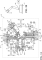
- a fixture assembly 10 is provided for forming a component, such as a door ring 12 for an automobile out of a plurality of blanks 14, 16.
- the blanks 14, 16 are sheets of steel, however, it should be appreciated that various types of blanks may be employed.
- the blanks 14, 16 may initially be comprised of a plurality of blank components 14A-C, 16A-C that may together be formed to provide the blanks 14, 16.
- the blanks 13, 16 and associated blank components 14A-C, 16A-C may have various shapes and sizes for ultimately providing different components. Additionally, it should be appreciated that any number of blanks and blank components could be used depending on specific applications.
- laser shearing and laser welding methods are employed to cut and weld the blanks 14, 16, however, it should be appreciated that the fixture assembly 10 and associated method may be used in conjunction with other types of shearing and welding systems.
- the fixture assembly 10 is generally shown.
- the fixture assembly 10 may be arranged in an operation cell.
- the fixture assembly 10 includes a first fixture subassembly 18 and a second fixture subassembly 20 that are configured to hold and selectively move the blanks 14, 16 during cutting and welding operations.
- the system also includes a shearing device 22 (schematically shown in FIG. 1B ) for shearing / cutting the blanks, and a welding device 24 (schematically shown in FIG. 1B ) for welding the blanks 14, 16.
- the shearing device 22 is a laser cutter
- the welding device 24 is a laser welder, but other shearing and welding devices could be employed without departing from the scope of the subject disclosure.
- an edge shape of a blank cut with a laser shearing device does not have roll and brake characteristics commonly associated with traditional mechanically sheared edges.
- the shearing and welding devices 22, 24 may be manually moveable, or moveable by way of a machine device such as a robotic arm 26.
- the various actuators discussed herein and the shearing and welding devices 22, 24 and associated robotic arm 26 (or other moving mechanism) are electrically connected to a controller 28 (schematically shown in FIG. 1A ) for receiving instructions from the controller 28.
- the controller 28 may actively provide instructions from an operator and/or may be programmed with predetermined instructions.
- the various actuators discussed herein may be various styles of actuators including, but not limited to, servo, pneumatic and hydraulic driven actuators, without departing from the scope of the subject disclosure.
- the robotic arm 26 may be a five-axis robotic arm that is configured to move in any direction in response to instructions from the controller 28.
- Three-dimensional coordinates of the shearing and welding devices 22, 24 on the robotic arm 26 may be tracked by the controller 28.
- the shearing and welding devices 22, 24 may be configured as two heads on the robotic arm 26.
- a location tracking system 29 (schematically shown), e.g., cameras and sensors, may be employed to track movements of all components of the subject fixture assembly 10 and blanks 14, 16 in order to aid in identifying cutting and welding locations and movements of the various components of the fixture assembly 10.
- These location tracking capabilities allow cutting and welding outputs to be locationally tracked by the controller 28 at all times, which provides repeatable shearing and welding operations.
- the location tracking mechanism 29 allows the cutting and thereby blank trim locations to absolutely be known within the machine and always accurate to one another. This information may also be used to provide predetermined welding paths for final welds.
- the first and second fixture subassemblies 18, 20 each include a lower portion that is fixed to a support surface such as a floor, and an upper portion 30 that is moveable relative to the lower portion along a plane.
- the fixture assembly 10 could be configured such that only one of the fixture subassemblies includes a moveable upper portion 30.
- One or more fixture actuators 32 (schematically shown) are provided for moving the upper portion 30 of the first and / or second fixture subassemblies 18, 20.
- the moveable upper portion 30 may be configured to be moveable only in single directions which edges of the blanks 14, 16 to be moved toward one another to provide more simple tracking of the fixture subassemblies.
- the entire fixture subassemblies 18, 20 could be configured to move, instead of just an upper portion 30 thereof so long as they are capable of moving the blanks 14, 16 relative to one another.
- Each of the fixture subassemblies 18, 20 includes two moveable blank supports 34 that are moveably connected to the upper portion 30 in directions parallel to the plane, and configured to support and provide movement to the components 14A-C, 16A-C of the blanks 14, 16.
- the blank supports 34 could also be configured to rotate.
- a plurality of blank support actuators 36 (schematically shown) are each configured to move one of the moveable blank supports 34 in any direction parallel to the plane.
- a plurality of moving support plates 38 are fixed to, and moveable with the moveable blank supports 34.
- the moving support plates 38 each have a planar top surface for supporting the blanks 14, 16 during use of the fixture assembly 10.
- Each of the fixture subassemblies 18, 20 also includes a plurality of stationary support plates 40 fixed to the upper portion 30.
- the stationary support plates 40 have a planar top surface for supporting the blanks 14, 16 during use of the fixture assembly 10.
- Each of the fixture subassemblies 18, 20 further includes a pair of electromagnets 42, each positioned on one of the moveable blank supports 34 such that they are moveable with the moveable blank supports 34.
- the electromagnets 42 each have a planar top surface for supporting one of the blanks 14, 16.
- the electromagnets 42 are configured to draw the blanks 14, 16 toward the top surface when activated in order to ensure that the blanks 14, 16 remain flat and do not move during cutting, welding and blank moving operations.
- the electromagnets 42 are each located adjacent to an edge of the upper portion 30 and extend parallel with another of the electromagnets 42 such that the electromagnets 42 may position edges of the blanks 14, 16 on opposing fixture subassemblies 18, 20 in adjacent spaced and parallel relationship with one another (as shown in FIG. 2 ).
- Each of the fixture subassemblies 18, 20 also includes a plurality of intensifiers 44 that are each configured to selectively overlie one of the electromagnets 42 to intensify a magnetic field of the electromagnets 42 to ensure that while the blanks 14, 16 overlie the electromagnets 42, they remain flat and do not move during cutting and welding operations.
- the intensifiers 44 are of a ferromagnetic material such that when they overlie the electromagnets and blanks 14, 16, they are drawn toward the electromagnet 42 and thus clamp the blank 14, 16 that is positioned between the intensifier 44 and electromagnet 42 in place (see, e.g., FIGS. 3 , 4 ).
- a plurality of intensifier actuators 46 are each configured to selectively pivot one of the intensifiers 44 over the electromagnets 42.
- FIG. 2 shows the intensifiers 44 in a vertical position in which they do not overlie the electromagnets 42
- FIG. 3 shows the intensifiers 44 in a horizontal position in which they overlie the electromagnets 42.
- the intensifier actuators 46 are pneumatic cylinders, but other types of actuators could be employed without departing from the scope of the subject disclosure.
- the fixture assembly 10 further includes a plurality of clamp arms 48 that are each configured to selectively overly one of the support plates 38, 40 to further ensure that the blanks 14, 16 remain flat and do not move during cutting, welding and blank moving operations.
- a plurality of clamp actuators 50 are configured to selectively pivot the clamp arms 48 over the support plates 38, 40.
- FIG. 3 shows the clamp arms 48 in a vertical position in which they do not overlie the support plates 38, 40
- FIG. 3 shows the clamp arms 48 in a horizontal position in which they overlie the support plates 38, 40.
- the clamp actuators 50 of the example embodiment are pneumatic cylinders, but other actuators could be used.
- electromagnets 42 and associated intensifiers 44 could be employed to hold the blanks 14, 16 in different regions of the fixture assembly 10 depending on specific needs.
- the electromagnets 42 and intensifiers 44 are used at the edge regions of the fixture subassemblies 18, 20 because shearing and welding of blanks 14, 16 occurs at the edge regions, which mandates a very secure connection.
- FIG. 8 is a flow diagram illustrating a method of using the subject fixture assembly 10 to fabricate a component out of a plurality of blanks 14, 16.
- the method starts with 500 providing an empty fixture assembly 10.
- the method continues with 502 positioning a plurality of blank components 14A-C, 16A-C on the first and second fixture subassemblies 18, 20 of the fixture assembly 10. More particularly, as shown, a first component 14A of the first blank 14 is positioned such that it rests on an electromagnet 42 and one of the moving support plates 38, with an edge thereof positioned along an edge of the first fixture subassembly 18 along a gap between the first and second fixture subassemblies 18, 20.
- a second component 14B of the first blank 14 is positioned in the same manner on the other of the electromagnets 42 and another of the moving support plates 38.
- a third component 14C of the first blank 14 is positioned on two of the stationary support plates 40, Because the first and second components 14A, 14B of the first blank 14 reside on moveable blank supports 34, they are moveable relative to the third component 14C of the first blank 14.
- first, second and third components 16A-C of the second blank 16 are arranged in the same manner as the first, second and third components 14A-C of the first fixture subassembly 18, only on the second fixture subassembly 20.
- electromagnets 42 and support plates 38, 40 may vary depending on shapes and sizes of the blank components, and more or fewer electromagnets 42 and support plates 38, 40 could be used depending on how many blank components are used, and their shapes and sizes.
- the method continues with 504 moving the first and second components 14A, 14B of the first blank 14 toward the fixed third component 14C of the first blank 14 by way of the moveable blank supports 34 and associated blank support actuators 36 such that edges of the first and second components 14A, 14B lie flush against edges of the third component 14C.
- the method continues with 506 moving the first and second components 16A, 16B, 16C of the second blank 16 in the same manner.
- the method continues with 508 welding the engaging edges of the first and second components 14A-B, 16A-B to the edges of the third component 14C, 16C on each of the first and second blanks 14, 16 in order to provide completed first and second blank components 14, 16.
- the method continues with 510 fixing the first and second blanks 14, 16 in place on the first and second fixture subassemblies 18, 20.
- this includes activating the electromagnets 42 and pivoting the intensifiers 44 and clamp arms 48 over the first and second blanks 14, 16.
- the method continues with 512 cutting parallel and adjacent edges 52 of the first and second blanks 14, 16 with the shearing device 22 to define sheared edges 52 along each of the first and second blanks 14, 16.
- the method continues with 514 moving the first fixture subassembly 18 toward the second fixture subassembly 20 such that the sheared edges 52 of the first and second blanks 14, 16 are positioned flush against one another. More particularly, according to the example embodiment, the upper portion 30 of the first fixture subassembly 18 is moved toward the upper portion 30 of the second fixture subassembly 20, with the fixture actuator 32.
- moving components could be employed to align the sheared edges 52 of the first and second blanks 14, 16 with one another.
- both fixture subassemblies 18, 20 could be moved toward one another, or one or both of the entire fixture subassemblies 18, 20 could be moved toward one another.
- the fixture subassemblies 18 could be configured such that they are only capable of moving the blanks 14, 16 at this step in a horizontal directions toward one another, thereby simplifying tracking of the sheared edges 52 of the blanks 14, 16 to provide more reproducible and predictable welding operations, and simplifying the type of actuator used.
- the method continues with 516 welding the first and second sheared edges 52 to one another with the welding device 24 to form the final component, in this case a door ring 12.
- the method includes 518 unfixing the finished component 12 from the fixture assembly 10. According to the example embodiment, this includes deactivating the electromagnets 42 and releasing the intensifiers 44 and clamp arms 48.
- the controller 28 and tracking system 29 may be employed to track the locations of the shearing and welding devices 22, 24, the blanks 14, 16, notably the edges 52 of the blanks 14, 16, as well as the movable components of the fixture assembly 10 in order to permit the above-referenced method to repeatedly be produced either manually or automatically via instructions from the controller 28.
- the tracking system 29 may be employed to actively adjust the various moving components based on present locations and to guide the shearing and welding devices 22, 24.
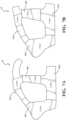
- the blank components 14A-C, 16A-C may be comprised of different materials than one another for providing different characteristics at different locations of the door ring 12, for example, to provide different strength and weight attributes along different regions.
- the three uppermost blank components 14A, 16A, 16C may be made of an uncoated material, and the three lowermost blanks 14C, 14B, 16B can be made of a hot-dipped / coated material.
- FIGS. 6A and 6B further illustrate that the blanks 14, 16 and blank components 14A-C, 16A-C may have various shapes depending on specific applications. With reference to FIGS.
- the blank components 14A, 14C, 16A, 16C may be of different thicknesses / gauge to provide different strength and weight characteristics at different regions. Furthermore, it should be appreciated that the blanks 14, 16 may be cold-stamped prior to connection with one another. Furthermore, as illustrated in FIGS. 7A-7B fewer blank components may be employed to arrive at the final component, like the four piece assembly shown.
- laser cutting and welding may be performed on the component 12 with all components connected to a single fixture assembly 10.
- cutting and welding locations are easily tracked throughout the process, thereby providing faster cycle times and the elimination of tolerance stack-up issues.
- This is contrary to conventional systems for welding door ring blanks where blanks are removed from a fixture assembly prior to welding to be sheared and then reintroduced to the fixture a second time.
- a single direction movement may be employed to bring the edges 52 of the first and second blanks 14, 16 in proximity to one another for welding.
- the electromagnets 42 and intensifiers 44 and clamp arms 48 may remain active to ensure that the blanks 14, 16 do not move relative to one another during shearing and welding, and thus only easily trackable movements of the shearing and welding devices 22, 24 and blanks 14, 16 are required. This renders only movement of the shearing and welding devices 22, 24 as the primary feature that requires tracking throughout the process, and substantially the only potential source for error. Furthermore, because a common axis may be used for both the shearing and welding devices 22, 24, shearing locations are easily trackable and location information can be used for easily identifying welding paths.
Landscapes
- Engineering & Computer Science (AREA)
- Physics & Mathematics (AREA)
- Optics & Photonics (AREA)
- Mechanical Engineering (AREA)
- Plasma & Fusion (AREA)
- Transportation (AREA)
- Chemical & Material Sciences (AREA)
- Combustion & Propulsion (AREA)
- Robotics (AREA)
- Manufacturing & Machinery (AREA)
- Architecture (AREA)
- Structural Engineering (AREA)
- Automatic Assembly (AREA)
- Butt Welding And Welding Of Specific Article (AREA)
Applications Claiming Priority (3)
| Application Number | Priority Date | Filing Date | Title |
|---|---|---|---|
| US202163173008P | 2021-04-09 | 2021-04-09 | |
| PCT/CA2022/050557 WO2022213219A1 (en) | 2021-04-09 | 2022-04-11 | System for welding multiple blanks into a component |
| EP22783755.6A EP4319940A4 (de) | 2021-04-09 | 2022-04-11 | System zum verschweissen mehrerer rohlinge zu einem bauteil |
Related Parent Applications (1)
| Application Number | Title | Priority Date | Filing Date |
|---|---|---|---|
| EP22783755.6A Division EP4319940A4 (de) | 2021-04-09 | 2022-04-11 | System zum verschweissen mehrerer rohlinge zu einem bauteil |
Publications (2)
| Publication Number | Publication Date |
|---|---|
| EP4403296A2 true EP4403296A2 (de) | 2024-07-24 |
| EP4403296A3 EP4403296A3 (de) | 2024-12-18 |
Family
ID=83544908
Family Applications (2)
| Application Number | Title | Priority Date | Filing Date |
|---|---|---|---|
| EP22783755.6A Pending EP4319940A4 (de) | 2021-04-09 | 2022-04-11 | System zum verschweissen mehrerer rohlinge zu einem bauteil |
| EP24179952.7A Pending EP4403296A3 (de) | 2021-04-09 | 2022-04-11 | System zum verschweissen mehrerer rohlinge zu einem bauteil |
Family Applications Before (1)
| Application Number | Title | Priority Date | Filing Date |
|---|---|---|---|
| EP22783755.6A Pending EP4319940A4 (de) | 2021-04-09 | 2022-04-11 | System zum verschweissen mehrerer rohlinge zu einem bauteil |
Country Status (6)
| Country | Link |
|---|---|
| US (1) | US20240189950A1 (de) |
| EP (2) | EP4319940A4 (de) |
| CN (1) | CN117157167A (de) |
| CA (1) | CA3214195A1 (de) |
| MX (1) | MX2023011706A (de) |
| WO (1) | WO2022213219A1 (de) |
Families Citing this family (6)
| Publication number | Priority date | Publication date | Assignee | Title |
|---|---|---|---|---|
| DE102023111811A1 (de) * | 2023-05-05 | 2024-11-07 | Baosteel Lasertechnik Gmbh | Laservorrichtung und Verfahren, insbesondere zur Herstellung eines ringförmig, geschlossenen Bauteils |
| CN116787053B (zh) * | 2023-06-28 | 2024-05-14 | 武汉宁致远汽车配件有限公司 | 一种柔性变位夹具以及基于该夹具的拼焊工艺 |
| US20250345880A1 (en) | 2024-05-08 | 2025-11-13 | Magna International Inc. | Method of tracking a blank edge for laser cutting |
| CN119141218B (zh) * | 2024-11-19 | 2025-05-16 | 昆山宝锦激光拼焊有限公司 | 一种门环自动拼接设备及控制方法 |
| CN119347127B (zh) * | 2024-12-27 | 2025-04-22 | 华安钢宝利高新汽车板加工(常熟)有限公司 | 一种板料加工用快速定位平台 |
| CN119566608B (zh) * | 2025-02-07 | 2025-07-01 | 天津杰斯特科技有限公司 | 一种具备焊接活口的门环焊接设备及焊接制造工艺 |
Family Cites Families (6)
| Publication number | Priority date | Publication date | Assignee | Title |
|---|---|---|---|---|
| CA2358279A1 (en) * | 2001-10-04 | 2003-04-04 | Bob Bishop | High speed welding apparatus with interchangeable weld fixture capability |
| JP4786401B2 (ja) * | 2006-04-14 | 2011-10-05 | 新日本製鐵株式会社 | 突合せ溶接金属板の製造方法 |
| DE102007023017B4 (de) * | 2007-05-15 | 2011-06-01 | Thyssenkrupp Lasertechnik Gmbh | Vorrichtung und Verfahren zum Herstellen von Tailored Blanks |
| WO2010071109A1 (ja) * | 2008-12-16 | 2010-06-24 | 株式会社Ihi | 溶接加工装置及びこれを用いた溶接加工方法 |
| EP3717173B1 (de) * | 2017-11-29 | 2024-06-05 | Magna International Inc. | Fixierungsanordnung und verfahren für schweissarbeiten |
| CN110102888A (zh) | 2019-01-31 | 2019-08-09 | 苏州普热斯勒先进成型技术有限公司 | 一种汽车门环拼焊板坯料的加工系统及方法 |
-
2022
- 2022-04-11 US US18/286,179 patent/US20240189950A1/en active Pending
- 2022-04-11 EP EP22783755.6A patent/EP4319940A4/de active Pending
- 2022-04-11 EP EP24179952.7A patent/EP4403296A3/de active Pending
- 2022-04-11 CA CA3214195A patent/CA3214195A1/en active Pending
- 2022-04-11 MX MX2023011706A patent/MX2023011706A/es unknown
- 2022-04-11 CN CN202280027414.6A patent/CN117157167A/zh active Pending
- 2022-04-11 WO PCT/CA2022/050557 patent/WO2022213219A1/en not_active Ceased
Also Published As
| Publication number | Publication date |
|---|---|
| EP4403296A3 (de) | 2024-12-18 |
| EP4319940A1 (de) | 2024-02-14 |
| WO2022213219A1 (en) | 2022-10-13 |
| US20240189950A1 (en) | 2024-06-13 |
| MX2023011706A (es) | 2023-10-12 |
| CN117157167A (zh) | 2023-12-01 |
| EP4319940A4 (de) | 2025-07-16 |
| CA3214195A1 (en) | 2022-10-13 |
Similar Documents
| Publication | Publication Date | Title |
|---|---|---|
| EP4403296A2 (de) | System zum verschweissen mehrerer rohlinge zu einem bauteil | |
| EP3717173B1 (de) | Fixierungsanordnung und verfahren für schweissarbeiten | |
| CN114616075B (zh) | 用于在剪切和焊接操作期间支承坯件的夹具组件 | |
| JPH0436792B2 (de) | ||
| CA2127023C (en) | Apparatus for clamping and welding | |
| CN110102888A (zh) | 一种汽车门环拼焊板坯料的加工系统及方法 | |
| JP2017030104A (ja) | 組立体製造装置及び組立体製造方法 | |
| JP2002059280A (ja) | 複数の厚さを有する半製品の製造方法 | |
| US6491210B1 (en) | Method and apparatus of butt welding | |
| WO2020217698A1 (ja) | 加工装置及び加工方法 | |
| JP3412402B2 (ja) | ブランク材の突き合わせ位置決め装置及びブランク材の突き合わせ位置決め方法 | |
| JPH02133195A (ja) | 溶接用拘束装置 | |
| JP3861344B2 (ja) | ブランク材の突き合わせ位置決め装置 | |
| US11654517B2 (en) | Fastener welding apparatus | |
| JP2001225242A (ja) | 加工治具 | |
| US20060027541A1 (en) | Programmable non-contact fusion welding apparatus and method | |
| JPS59206176A (ja) | 単一溶接電極を使用する産業用ロボツトスポツト溶接構造 | |
| JP2003275883A (ja) | 板材の突き合わせ接合方法 | |
| JPS59109472A (ja) | 車体組立用のワーク位置決め装置 | |
| JP2011510821A (ja) | ホルダ | |
| JP2009195932A (ja) | スポット溶接ロボットを使用する溶接システム | |
| KR102822093B1 (ko) | 듀얼식 카울크로스 부품의 용접 및 검사시스템 | |
| KR100273659B1 (ko) | 2차원 테일러드블랭크 용접시스템 | |
| CN213672361U (zh) | 一种机器人焊接车桥后盖装置 | |
| DE20112023U1 (de) | Rollenandruckkopf mit integriertem taktilen Nahtverfolgungssystem |
Legal Events
| Date | Code | Title | Description |
|---|---|---|---|
| PUAI | Public reference made under article 153(3) epc to a published international application that has entered the european phase |
Free format text: ORIGINAL CODE: 0009012 |
|
| STAA | Information on the status of an ep patent application or granted ep patent |
Free format text: STATUS: THE APPLICATION HAS BEEN PUBLISHED |
|
| AC | Divisional application: reference to earlier application |
Ref document number: 4319940 Country of ref document: EP Kind code of ref document: P |
|
| AK | Designated contracting states |
Kind code of ref document: A2 Designated state(s): AL AT BE BG CH CY CZ DE DK EE ES FI FR GB GR HR HU IE IS IT LI LT LU LV MC MK MT NL NO PL PT RO RS SE SI SK SM TR |
|
| PUAL | Search report despatched |
Free format text: ORIGINAL CODE: 0009013 |
|
| AK | Designated contracting states |
Kind code of ref document: A3 Designated state(s): AL AT BE BG CH CY CZ DE DK EE ES FI FR GB GR HR HU IE IS IT LI LT LU LV MC MK MT NL NO PL PT RO RS SE SI SK SM TR |
|
| RIC1 | Information provided on ipc code assigned before grant |
Ipc: B23K 26/60 20140101ALI20241113BHEP Ipc: B23K 26/38 20140101ALI20241113BHEP Ipc: B23K 26/21 20140101ALI20241113BHEP Ipc: B23K 101/18 20060101ALI20241113BHEP Ipc: B23K 101/00 20060101ALI20241113BHEP Ipc: B23K 37/047 20060101AFI20241113BHEP Ipc: B23K 37/04 20060101ALI20241113BHEP |
|
| STAA | Information on the status of an ep patent application or granted ep patent |
Free format text: STATUS: REQUEST FOR EXAMINATION WAS MADE |
|
| 17P | Request for examination filed |
Effective date: 20250602 |