EP4403291A1 - Dispositif de soudage par ultrasons - Google Patents
Dispositif de soudage par ultrasons Download PDFInfo
- Publication number
- EP4403291A1 EP4403291A1 EP24150543.7A EP24150543A EP4403291A1 EP 4403291 A1 EP4403291 A1 EP 4403291A1 EP 24150543 A EP24150543 A EP 24150543A EP 4403291 A1 EP4403291 A1 EP 4403291A1
- Authority
- EP
- European Patent Office
- Prior art keywords
- ultrasonic welding
- welding device
- busbar
- external
- ultrasonic
- Prior art date
- Legal status (The legal status is an assumption and is not a legal conclusion. Google has not performed a legal analysis and makes no representation as to the accuracy of the status listed.)
- Pending
Links
Images





Classifications
-
- B—PERFORMING OPERATIONS; TRANSPORTING
- B23—MACHINE TOOLS; METAL-WORKING NOT OTHERWISE PROVIDED FOR
- B23K—SOLDERING OR UNSOLDERING; WELDING; CLADDING OR PLATING BY SOLDERING OR WELDING; CUTTING BY APPLYING HEAT LOCALLY, e.g. FLAME CUTTING; WORKING BY LASER BEAM
- B23K20/00—Non-electric welding by applying impact or other pressure, with or without the application of heat, e.g. cladding or plating
- B23K20/10—Non-electric welding by applying impact or other pressure, with or without the application of heat, e.g. cladding or plating making use of vibrations, e.g. ultrasonic welding
- B23K20/106—Features related to sonotrodes
-
- B—PERFORMING OPERATIONS; TRANSPORTING
- B23—MACHINE TOOLS; METAL-WORKING NOT OTHERWISE PROVIDED FOR
- B23K—SOLDERING OR UNSOLDERING; WELDING; CLADDING OR PLATING BY SOLDERING OR WELDING; CUTTING BY APPLYING HEAT LOCALLY, e.g. FLAME CUTTING; WORKING BY LASER BEAM
- B23K20/00—Non-electric welding by applying impact or other pressure, with or without the application of heat, e.g. cladding or plating
- B23K20/10—Non-electric welding by applying impact or other pressure, with or without the application of heat, e.g. cladding or plating making use of vibrations, e.g. ultrasonic welding
-
- B—PERFORMING OPERATIONS; TRANSPORTING
- B23—MACHINE TOOLS; METAL-WORKING NOT OTHERWISE PROVIDED FOR
- B23K—SOLDERING OR UNSOLDERING; WELDING; CLADDING OR PLATING BY SOLDERING OR WELDING; CUTTING BY APPLYING HEAT LOCALLY, e.g. FLAME CUTTING; WORKING BY LASER BEAM
- B23K20/00—Non-electric welding by applying impact or other pressure, with or without the application of heat, e.g. cladding or plating
- B23K20/26—Auxiliary equipment
-
- B—PERFORMING OPERATIONS; TRANSPORTING
- B23—MACHINE TOOLS; METAL-WORKING NOT OTHERWISE PROVIDED FOR
- B23K—SOLDERING OR UNSOLDERING; WELDING; CLADDING OR PLATING BY SOLDERING OR WELDING; CUTTING BY APPLYING HEAT LOCALLY, e.g. FLAME CUTTING; WORKING BY LASER BEAM
- B23K31/00—Processes relevant to this subclass, specially adapted for particular articles or purposes, but not covered by any single one of main groups B23K1/00 - B23K28/00
- B23K31/003—Processes relevant to this subclass, specially adapted for particular articles or purposes, but not covered by any single one of main groups B23K1/00 - B23K28/00 relating to controlling of welding distortion
-
- B—PERFORMING OPERATIONS; TRANSPORTING
- B23—MACHINE TOOLS; METAL-WORKING NOT OTHERWISE PROVIDED FOR
- B23K—SOLDERING OR UNSOLDERING; WELDING; CLADDING OR PLATING BY SOLDERING OR WELDING; CUTTING BY APPLYING HEAT LOCALLY, e.g. FLAME CUTTING; WORKING BY LASER BEAM
- B23K37/00—Auxiliary devices or processes, not specially adapted for a procedure covered by only one of the other main groups of this subclass
- B23K37/04—Auxiliary devices or processes, not specially adapted for a procedure covered by only one of the other main groups of this subclass for holding or positioning work
- B23K37/0408—Auxiliary devices or processes, not specially adapted for a procedure covered by only one of the other main groups of this subclass for holding or positioning work for planar work
-
- B—PERFORMING OPERATIONS; TRANSPORTING
- B23—MACHINE TOOLS; METAL-WORKING NOT OTHERWISE PROVIDED FOR
- B23K—SOLDERING OR UNSOLDERING; WELDING; CLADDING OR PLATING BY SOLDERING OR WELDING; CUTTING BY APPLYING HEAT LOCALLY, e.g. FLAME CUTTING; WORKING BY LASER BEAM
- B23K37/00—Auxiliary devices or processes, not specially adapted for a procedure covered by only one of the other main groups of this subclass
- B23K37/04—Auxiliary devices or processes, not specially adapted for a procedure covered by only one of the other main groups of this subclass for holding or positioning work
- B23K37/0426—Fixtures for other work
- B23K37/0435—Clamps
- B23K37/0443—Jigs
-
- H—ELECTRICITY
- H01—ELECTRIC ELEMENTS
- H01M—PROCESSES OR MEANS, e.g. BATTERIES, FOR THE DIRECT CONVERSION OF CHEMICAL ENERGY INTO ELECTRICAL ENERGY
- H01M50/00—Constructional details or processes of manufacture of the non-active parts of electrochemical cells other than fuel cells, e.g. hybrid cells
- H01M50/50—Current conducting connections for cells or batteries
- H01M50/502—Interconnectors for connecting terminals of adjacent batteries; Interconnectors for connecting cells outside a battery casing
- H01M50/514—Methods for interconnecting adjacent batteries or cells
- H01M50/516—Methods for interconnecting adjacent batteries or cells by welding, soldering or brazing
-
- H—ELECTRICITY
- H01—ELECTRIC ELEMENTS
- H01M—PROCESSES OR MEANS, e.g. BATTERIES, FOR THE DIRECT CONVERSION OF CHEMICAL ENERGY INTO ELECTRICAL ENERGY
- H01M50/00—Constructional details or processes of manufacture of the non-active parts of electrochemical cells other than fuel cells, e.g. hybrid cells
- H01M50/50—Current conducting connections for cells or batteries
- H01M50/502—Interconnectors for connecting terminals of adjacent batteries; Interconnectors for connecting cells outside a battery casing
- H01M50/521—Interconnectors for connecting terminals of adjacent batteries; Interconnectors for connecting cells outside a battery casing characterised by the material
- H01M50/522—Inorganic material
-
- H—ELECTRICITY
- H01—ELECTRIC ELEMENTS
- H01M—PROCESSES OR MEANS, e.g. BATTERIES, FOR THE DIRECT CONVERSION OF CHEMICAL ENERGY INTO ELECTRICAL ENERGY
- H01M50/00—Constructional details or processes of manufacture of the non-active parts of electrochemical cells other than fuel cells, e.g. hybrid cells
- H01M50/50—Current conducting connections for cells or batteries
- H01M50/528—Fixed electrical connections, i.e. not intended for disconnection
-
- H—ELECTRICITY
- H01—ELECTRIC ELEMENTS
- H01R—ELECTRICALLY-CONDUCTIVE CONNECTIONS; STRUCTURAL ASSOCIATIONS OF A PLURALITY OF MUTUALLY-INSULATED ELECTRICAL CONNECTING ELEMENTS; COUPLING DEVICES; CURRENT COLLECTORS
- H01R43/00—Apparatus or processes specially adapted for manufacturing, assembling, maintaining, or repairing of line connectors or current collectors or for joining electric conductors
- H01R43/02—Apparatus or processes specially adapted for manufacturing, assembling, maintaining, or repairing of line connectors or current collectors or for joining electric conductors for soldered or welded connections
- H01R43/0207—Ultrasonic-, H.F.-, cold- or impact welding
-
- B—PERFORMING OPERATIONS; TRANSPORTING
- B23—MACHINE TOOLS; METAL-WORKING NOT OTHERWISE PROVIDED FOR
- B23K—SOLDERING OR UNSOLDERING; WELDING; CLADDING OR PLATING BY SOLDERING OR WELDING; CUTTING BY APPLYING HEAT LOCALLY, e.g. FLAME CUTTING; WORKING BY LASER BEAM
- B23K2101/00—Articles made by soldering, welding or cutting
- B23K2101/36—Electric or electronic devices
- B23K2101/38—Conductors
-
- B—PERFORMING OPERATIONS; TRANSPORTING
- B23—MACHINE TOOLS; METAL-WORKING NOT OTHERWISE PROVIDED FOR
- B23K—SOLDERING OR UNSOLDERING; WELDING; CLADDING OR PLATING BY SOLDERING OR WELDING; CUTTING BY APPLYING HEAT LOCALLY, e.g. FLAME CUTTING; WORKING BY LASER BEAM
- B23K2103/00—Materials to be soldered, welded or cut
- B23K2103/08—Non-ferrous metals or alloys
- B23K2103/10—Aluminium or alloys thereof
-
- Y—GENERAL TAGGING OF NEW TECHNOLOGICAL DEVELOPMENTS; GENERAL TAGGING OF CROSS-SECTIONAL TECHNOLOGIES SPANNING OVER SEVERAL SECTIONS OF THE IPC; TECHNICAL SUBJECTS COVERED BY FORMER USPC CROSS-REFERENCE ART COLLECTIONS [XRACs] AND DIGESTS
- Y02—TECHNOLOGIES OR APPLICATIONS FOR MITIGATION OR ADAPTATION AGAINST CLIMATE CHANGE
- Y02E—REDUCTION OF GREENHOUSE GAS [GHG] EMISSIONS, RELATED TO ENERGY GENERATION, TRANSMISSION OR DISTRIBUTION
- Y02E60/00—Enabling technologies; Technologies with a potential or indirect contribution to GHG emissions mitigation
- Y02E60/10—Energy storage using batteries
Definitions
- the present disclosure relates to an ultrasonic welding device. More particularly, the present disclosure relates to an ultrasonic welding device for ultrasonically welding flexible members.
- An ultrasonic welding is a solid-state welding in which welding is performed at a low temperature compared with arc welding or laser welding in a short time. It is an environmentally-friendly welding that may connect only a specific part. Therefore, the ultrasonic welding is widely used in welding of battery, electronic industry and its parts.
- a horn design is optimized according to a structure and thickness of the welding material.
- the appearance and the structure become non-uniform because of excessive deformation of the ductile material. By this, cracks are generated in the flexible material, leading to a product failure.
- a secondary battery module may be formed by connecting cylindrical secondary battery cells in series/parallel.
- an upper flexible busbar member also referred to as an upper member
- a lower flexible busbar member also referred to as a lower member
- a guide jig is used to designate and hold a position of the upper member from among the upper and lower members, and ultrasonic welding is performed thereto.
- lifting may be generated around the welding portion, and as a result, quality defects may occur because of interface cracks and thickness imbalance between the upper member and the lower member.
- the present disclosure has been made in an effort to provide an ultrasonic welding device for controlling deformation of flexible materials during welding, and increasing rigidity and reliability of a welding portion.
- the present disclosure has been made in another effort to provide an ultrasonic welding device for, if welding flexible busbar members made of aluminium, preventing members from lifting around a welding portion, preventing interface cracks and thickness imbalance between two members, and thereby increasing welding quality.
- An embodiment of the present disclosure provides an ultrasonic welding device including an anvil for supporting a flexible first member from among the first member and a flexible second member overlapping in a top to bottom direction and sequentially disposed from bottom to top; a horn for ultrasonically welding the first member and the second member by elevation and ultrasonic vibration at an upper portion of the second member; and a guide jig including an opening corresponding to a welding portion of the first member and the second member for guiding elevation and ultrasonic vibration of the horn, and covering an external plane around the welding portion with a plane corresponding portion so as to ultrasonically weld the first member and the second member.
- the plane corresponding portion may be formed as a same plane in four directions from among two sides of a length direction and two sides of a width direction of the first member and the second member on the external plane around the welding portion.
- the guide jig may further hold an external lateral side of the welding portion with a lateral corresponding portion.
- the lateral corresponding portion may protrude downward from the plane corresponding portion in three directions of one side of a length direction and two sides of a width direction from among the two sides of the length direction and the two sides of the width direction of the first member and the second member on the external plane around the welding portion.
- the guide jig may include a guide portion including the opening and the plane corresponding portion, and an installer connected to one side of the guide portion and installed in a base.
- the guide portion may have the opening in a center and an external portion outside the opening, and with respect to a length direction and a width direction of the first member and the second member, a first width of the opening in a width direction may be greater than a second width of the external portion in the width direction.
- a first length of the opening in the length direction may be greater than a second length of the external portion in the length direction on one side of the length direction.
- the second length may be greater than the second width.
- the first member may include a first busbar including branches connected to battery cells provided in a secondary battery module, and a second busbar spaced by a gap from the first busbar in a length direction and including branches connected to other battery cells, and the second member may connect the first busbar and the second busbar by ultrasonic welding.
- the first busbar may further include a first connector on one side of a width direction
- the second busbar may further include a second connector on one side of the width direction
- the second member may be connected to the first connector and the second connector by ultrasonic welding.
- the first member and the second member may be made of aluminium.
- the first member and the second member may be made of an aluminium material, and the horn may be made of a tungsten carbide material with strength and stiffness that are greater than those of the first member and the second member.
- the first member and the second member may be made of an aluminium material, and the guide jig may be made of a tungsten carbide material with strength and stiffness that are greater than those of the first member and the second member.
- the guide jig having an opening and a plane corresponding portion is applied to cover the plane external plane around the welding portion of the first and second members with the plane corresponding portion, and the elevation and ultrasonic vibration of the horn are guided through the opening, so that the ultrasonic welding may be performed.
- the deformation generated by the ultrasonic welding may be controlled. By this, increased strength and reliability of the welding portion may be obtained.
- the aluminium busbar members are covered by using the guide jig and are ultrasonically welded, thereby preventing the members from lifting around the welding portion.
- FIG. 1 shows a perspective view of applying flexible busbar members to an ultrasonic welding device according to an embodiment to weld the same
- FIG. 2 shows a perspective view of disassembled flexible busbar members, a horn, a guide jig, and an anvil of FIG. 1 .
- the ultrasonic welding device includes an anvil 30, a horn 40, and a guide jig 50 to perform ultrasonic welding to a first member 1 and a second member 2 that are flexible, overlap in a top-down direction (z-axis direction), and are sequentially disposed from bottom to top.
- the first member 1 may include a first busbar 11 and a second busbar 12, and the second member 2 may be connected to the first busbar 11 and the second busbar 12 at respective ends by ultrasonic welding. Therefore, the first busbar 11 may be connected to the second busbar 12 in a length direction (y-axis direction) by the second member 2.
- the first busbar 11 may have branches 111 connected to battery cells provided in a secondary battery module (not shown).
- the second busbar 12 may be spaced from the first busbar 11 by a gap G in the length direction (y-axis direction) and have branches 121 connected to other battery cells.
- the battery cells may be formed with a cylindrical secondary battery.
- the first and second busbars 11 and 12 that is the first member 1, and the second member 2 may connect the battery cells in series/parallel to form a secondary battery module.
- first and second members 1 and 2 may be made of a flexible material and are connected by ultrasonic welding so as to supplement electrical connection, structural rigidity, and structural vibration.
- first and second members 1 and 2 may be made of aluminium.
- FIG. 3 shows a perspective view of a connector of flexible busbar members applied to FIG. 1 and FIG. 2 .
- the first busbar 11 may further include a first connector 112 on one side of the width direction (x-axis direction).
- the second busbar 12 may be spaced from the first busbar 11 by the gap G and further includes second connector 122 on one side of the width direction (x-axis direction).
- the second member 2 may be connected to the first connector 112 and the second connector 122 at respective ends by ultrasonic welding. Therefore, the first busbar 11 and the second busbar 12 may be connected in the length direction (y-axis direction) by the second member 2, may be disposed in the secondary battery module, and may be electrically and mechanically connected to the battery cell.
- the anvil 30 may support first and second members 1 and 2 overlapping in the top to bottom direction (z-axis direction) and sequentially disposed from bottom to top so as to fluently transmit an amplitude of ultrasonic energy to the first and second members 1 and 2 to be welded.
- the anvil 30 may support the first busbar 11 or the second busbar 12 that is the first member 1 on a lower side.
- the anvil 30 may support the ultrasonic wave amplitude of the horn 30 during ultrasonic welding, may receive a pressure, and may further include an external support portion 31 outside the anvil 30.
- the external support portion 31 may support a state in which the first busbar 11 or the second busbar 12 that is the first member 1 on the lower side is disposed, and does not receive the pressure with the ultrasonic wave amplitude (refer to FIG. 6 and FIG. 7 ).
- the horn 40 ultrasonically welds the first member 1 and the second member 2 by elevation and ultrasonic vibration at an upper portion of the second member 2. That is, the horn 40 may apply the ultrasonic energy provided by the converter 41 and the booster 42 to the first and second member 1 and 2 to be welded, thereby forming a welding portion 23 (refer to FIG. 5 ).
- the first and second members 1 and 2 being welded, the first and second members 1 and 2 are supported by the anvil 30.
- the converter 41 may convert electrical energy into mechanical energy to generate the amplitude of ultrasonic energy.
- the booster 42 may receive the amplitude of ultrasonic energy from the converter 41, may increase/reduce the amplitude with a predetermined ratio, and may transmit a resultant amplitude to the horn 40.
- the guide jig 50 may be used in ultrasonically welding the first and second members 1 and 2 made of a flexible material such as aluminium.
- the first member 1 may include a first busbar 11 and a second busbar 12 made of aluminium.
- the guide jig 50 may control deformation generated if ultrasonically welding the first and second members 1 and 2, thereby increasing welding strength and welding reliability on the welding portion 23.
- the guide jig 50 may fix a position of the second member 2 on an upper side, and may surround a peripheral portion of the horn 40 to control lifting and deformation around the welding portion 23.
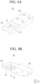
- FIG. 4A and FIG. 4B show perspective views of a guide jig seen from top and bottom.
- the guide jig 50 includes an opening 51 and a plane corresponding portion 52.
- the guide jig 50 may further include a lateral corresponding portion 53.
- FIG. 5 shows a top plan view in which a guide jig is disposed on flexible busbar members to be welded.
- the opening 51 forms a quadrangular closed space, enabling the horn 40 to ascend and descend and the amplitude operation of ultrasonic energy through the opening 51.
- the opening 51 is formed to penetrate the guide jig 50 corresponding to the welding portion 23 of the first and second members 1 and 2 for ultrasonically welding the first and second members 1 and 2, guide the elevation and ultrasonic vibration of the horn 40, and open the welding portion 23.
- FIG. 6 shows a cross-sectional view with respect to a line VI-VI of FIG. 5
- FIG. 7 shows a cross-sectional view with respect to a line VII-VII of FIG. 5
- the plane corresponding portion 52 formed on an external side of the opening 51 may allow formation of the welding portion 23 at a portion that corresponds to the opening 51, and may cover an external plane 24 around the welding portion 23 that is an upper side of the second member 2 and fix the same.
- the plane corresponding portion 52 may control deformation of the external plane 24 around the welding portion 23.
- the plane corresponding portion 52 may be formed as the same plane in four directions from among two sides of the length direction (y-axis direction) and two sides of the width direction (x-axis direction) of the first member 1 and the second member 2 on the external plane 24 around the welding portion 23.
- the guide jig 50 may further hold an external lateral side 25 of the welding portion 23 with the lateral corresponding portion 53.
- the lateral corresponding portion 53 may protrude downward from the plane corresponding portion 52 in the three directions of one side of the length direction (y-axis direction) and the two sides of the width direction (x-axis direction) from among the two sides of the length direction (y-axis direction) and the two sides of the width direction (x-axis direction) of the first member 1 and the second member 2 on the external plane 24 around the welding portion 23.
- the lateral corresponding portion 53 may have a height difference from the plane corresponding portion 52.
- the guide jig 50 may include a guide portion 501 and an installer 502.
- the guide portion 501 may include the opening 51 and the plane corresponding portion 52, and may further include the lateral corresponding portion 53.
- the installer 502 may be connected to one side of the guide portion 501 and may be installed in a base 60 of the ultrasonic welding device.
- the guide portion 501 has the opening 51 in the center and includes an external portion 511 outside the opening 51, and a first width W1 of the opening 51 in the width direction (x-axis direction) may be greater than a second width W2 of the external portion 511 in the width direction (x-axis direction) with respect to the length direction (y-axis direction) and the width direction (x-axis direction) of the first member 1 and the second member 2.
- a first length L1 of the opening 51 in the length direction (y-axis direction) may be greater than a second length L2 of the external portion 511 in the length direction (y-axis direction) on one side of the length direction (y-axis direction).
- the second length L2 may be greater than the second width W2.
- the second length L2 of the external portion 511 may prevent the second member 2 from lifting at the respective ends of the welding portion 23 in the length direction (y-axis direction), and for this purpose, the second length L2 may be sufficiently great.
- the second width W2 may prevent the second member 2 from lifting at the respective ends of the welding portion 23 in the width direction (x-axis direction), and for this purpose, it may have a sufficient length. That is, the second length L2 and the second width W2 of the external portion 511 may suppress deformation of the second member 2 disposed on the upper side around the welding portion 23 of the first and second members 1 and 2.
- the external portion 511 may be formed with the plane corresponding portion 52 around the opening 51, and as shown, it may further include a lateral corresponding portion 53 connected to the plane corresponding portion 52.
- the external portion 511 further including a lateral corresponding portion 53 may more firmly fix the upper side and the lateral side of the second member 2 around the welding portion 23 so it may further suppress deformation around the welding portion 23.
- FIG. 6 and FIG. 7 show that the guide jig 50 contacts the upper side and the lateral side of the second member 2.
- a gap spaced between the guide jig 50 and the second member 2 may be set according to power, pressure, and time of ultrasonic wave applied energy.
- the gap may be set by reflecting an optimized exterior and an allowable deformation level on the level of 1 mm.
- FIG. 8 shows an image if flexible busbar members are welded by using an ultrasonic welding device according to a comparative example 1
- FIG. 9 shows an image if flexible busbar members are welded by using an ultrasonic welding device according to a comparative example 2.
- the guide jig 50 may completely surround the opening 51 with the external portion 511, and according to comparative examples 1 and 2, a guide jig (not shown) may open one side of the opening to hold a member to be welded.
- the external portions 811 and 911 around the welding portions 822 and 922 are greatly deformed to generate lifting L8 and L9 and cracks C8 and C9.
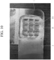
- FIG. 10 shows an image in a plan view if flexible busbar members are welded by using an ultrasonic welding device according to an embodiment
- FIG. 11 shows an image in a lateral view if flexible busbar members are welded by using an ultrasonic welding device according to an embodiment.
- the external plane 24 around the welding portion 23 is pressurized (P) by the external portion 511 and is maintained as fixed, the lifting and cracks described with reference to the comparative examples 1 and 2 are not generated.
- the external plane 24 around the welding portion 23 may be pressurized (P) by the plane corresponding portion 52, and a movement of the external lateral side 25 of the welding portion 23 may be restricted by the lateral corresponding portion 53. Therefore, the lifting and cracks around the welding portion 23 to which the first member 1 and the second member 2 are ultrasonically welded may be further prevented.
- the first and second members 1 and 2 may be made of an aluminium material.
- the horn 40 may be made of very hard tungsten (WC) or a tungsten carbide material with strength and stiffness that are greater than those of the first and second members 1 and 2.
- the guide jig 50 may be made of very hard tungsten (WC) or a tungsten carbide material with strength and stiffness that are greater than those of the first and second members 1 and 2.
Landscapes
- Engineering & Computer Science (AREA)
- Mechanical Engineering (AREA)
- Chemical & Material Sciences (AREA)
- Chemical Kinetics & Catalysis (AREA)
- Electrochemistry (AREA)
- General Chemical & Material Sciences (AREA)
- Physics & Mathematics (AREA)
- Optics & Photonics (AREA)
- Inorganic Chemistry (AREA)
- Manufacturing & Machinery (AREA)
- Pressure Welding/Diffusion-Bonding (AREA)
Applications Claiming Priority (1)
| Application Number | Priority Date | Filing Date | Title |
|---|---|---|---|
| KR1020230006356A KR20240114210A (ko) | 2023-01-16 | 2023-01-16 | 초음파 용접장치 |
Publications (1)
| Publication Number | Publication Date |
|---|---|
| EP4403291A1 true EP4403291A1 (fr) | 2024-07-24 |
Family
ID=89474445
Family Applications (1)
| Application Number | Title | Priority Date | Filing Date |
|---|---|---|---|
| EP24150543.7A Pending EP4403291A1 (fr) | 2023-01-16 | 2024-01-05 | Dispositif de soudage par ultrasons |
Country Status (4)
| Country | Link |
|---|---|
| US (1) | US20240238893A1 (fr) |
| EP (1) | EP4403291A1 (fr) |
| KR (1) | KR20240114210A (fr) |
| CN (1) | CN118342084A (fr) |
Citations (4)
| Publication number | Priority date | Publication date | Assignee | Title |
|---|---|---|---|---|
| US20120280019A1 (en) * | 2006-07-25 | 2012-11-08 | Jaguar Cars Limited | Ultrasonic welding apparatus |
| US20140048584A1 (en) * | 2010-03-31 | 2014-02-20 | Orthodyne Electronics Corporation | Ultrasonic bonding systems and methods of using the same |
| US9751257B2 (en) * | 2014-06-17 | 2017-09-05 | GM Global Technology Operations LLC | Ultrasonic welder clamp |
| DE102019120988A1 (de) * | 2019-08-02 | 2021-02-04 | Auto-Kabel Management Gmbh | Werkzeug zum Fixieren eines Bauteils zum stoffschlüssigen Fügen, Verfahren zum Ultraschallschweißen |
Family Cites Families (19)
| Publication number | Priority date | Publication date | Assignee | Title |
|---|---|---|---|---|
| GB1294973A (fr) * | 1969-02-12 | 1972-11-01 | ||
| JP2890335B2 (ja) * | 1991-07-15 | 1999-05-10 | 株式会社新川 | テープクランプ機構 |
| US5238174A (en) * | 1991-11-15 | 1993-08-24 | Kulicke And Soffa Investments, Inc. | Smart indexing head for universal lead frame work station |
| US5390844A (en) * | 1993-07-23 | 1995-02-21 | Tessera, Inc. | Semiconductor inner lead bonding tool |
| JP3151702B2 (ja) * | 1995-11-24 | 2001-04-03 | 株式会社新川 | ボンディング装置用クランプ機構 |
| JP2001244292A (ja) * | 2000-03-01 | 2001-09-07 | Mitsubishi Electric Corp | 半導体装置のワイヤボンデイング装置およびワイヤボンデイング方法 |
| US20090197160A1 (en) * | 2008-01-31 | 2009-08-06 | Sanyo Electric Co., Ltd. | Stack type battery |
| WO2010057016A2 (fr) * | 2008-11-13 | 2010-05-20 | Orthodyne Electronics Corporation | Support de dispositif semi-conducteur pour liaison |
| US8871376B2 (en) * | 2011-08-31 | 2014-10-28 | Lg Chem, Ltd. | Interconnection assemblies and methods for forming the interconnection assemblies in a battery module |
| CN107107252A (zh) * | 2014-08-25 | 2017-08-29 | 日产自动车株式会社 | 超声波接合装置 |
| US9475232B2 (en) * | 2014-12-01 | 2016-10-25 | Zee.Aero Inc. | Damping and isolating vibration during ultrasonic welding |
| JP6191588B2 (ja) * | 2014-12-09 | 2017-09-06 | トヨタ自動車株式会社 | 二次電池の製造方法 |
| DE102015106265A1 (de) * | 2015-02-06 | 2016-08-11 | Auto-Kabel Management Gmbh | Ultraschallschweißvorrichtung sowie Verfahren zum Ultraschallschweißen |
| WO2020163694A1 (fr) * | 2019-02-07 | 2020-08-13 | T.A. Systems, Inc. | Sonotrode à ultrasons dotée d'un outil de serrage de pièce |
| KR102710862B1 (ko) * | 2019-03-05 | 2024-09-27 | 삼성디스플레이 주식회사 | 표시 장치의 제조 장치 및 표시 장치의 제조 방법 |
| KR102738519B1 (ko) * | 2019-09-30 | 2024-12-04 | 현대자동차 주식회사 | 이차전지의 초음파 용접 시스템 및 이를 이용한 이차전지의 제조방법 |
| US11826861B1 (en) * | 2020-08-12 | 2023-11-28 | Sion Power Corporation | Joining systems, clamping fixtures, and related systems and methods |
| CN217142691U (zh) * | 2022-02-28 | 2022-08-09 | 宁德时代新能源科技股份有限公司 | 焊接设备及电池焊接设备 |
| KR20250003150A (ko) * | 2023-06-30 | 2025-01-07 | 삼성에스디아이 주식회사 | 전지 팩 |
-
2023
- 2023-01-16 KR KR1020230006356A patent/KR20240114210A/ko active Pending
- 2023-10-17 US US18/488,842 patent/US20240238893A1/en active Pending
-
2024
- 2024-01-05 EP EP24150543.7A patent/EP4403291A1/fr active Pending
- 2024-01-12 CN CN202410048479.XA patent/CN118342084A/zh active Pending
Patent Citations (4)
| Publication number | Priority date | Publication date | Assignee | Title |
|---|---|---|---|---|
| US20120280019A1 (en) * | 2006-07-25 | 2012-11-08 | Jaguar Cars Limited | Ultrasonic welding apparatus |
| US20140048584A1 (en) * | 2010-03-31 | 2014-02-20 | Orthodyne Electronics Corporation | Ultrasonic bonding systems and methods of using the same |
| US9751257B2 (en) * | 2014-06-17 | 2017-09-05 | GM Global Technology Operations LLC | Ultrasonic welder clamp |
| DE102019120988A1 (de) * | 2019-08-02 | 2021-02-04 | Auto-Kabel Management Gmbh | Werkzeug zum Fixieren eines Bauteils zum stoffschlüssigen Fügen, Verfahren zum Ultraschallschweißen |
Also Published As
| Publication number | Publication date |
|---|---|
| CN118342084A (zh) | 2024-07-16 |
| KR20240114210A (ko) | 2024-07-23 |
| US20240238893A1 (en) | 2024-07-18 |
Similar Documents
| Publication | Publication Date | Title |
|---|---|---|
| KR102738519B1 (ko) | 이차전지의 초음파 용접 시스템 및 이를 이용한 이차전지의 제조방법 | |
| US11949115B2 (en) | Multi-part battery module wall | |
| KR101189430B1 (ko) | 전지 모듈 및 전지 모듈의 제조 방법 | |
| US20230150072A1 (en) | Automatic pressure jig device for bringing electrode lead into close contact with busbar, and battery module manufacturing system comprising same | |
| JP5337586B2 (ja) | 密閉型電池および密閉型電池の製造方法 | |
| KR101858680B1 (ko) | 2차 전지용 셀의 폴딩 장치 및 방법 | |
| US20240347828A1 (en) | Side beam for battery tray, battery tray, battery pack and vehicle | |
| CN111448685B (zh) | 用于将电极引线紧密附着至汇流条的自动按压夹具设备 | |
| KR20170095067A (ko) | 레이저 용접된 전극 탭과 전극리드를 구비한 전지셀 | |
| WO2014034385A1 (fr) | Procédé de fabrication d'un dispositif d'accumulation d'électricité et dispositif d'accumulation d'électricité | |
| US20250153262A1 (en) | Welding Apparatus and Welding Method | |
| EP4432455A1 (fr) | Appareil de soudage de languette d'électrode, procédé de soudage de languette d'électrode et batterie secondaire | |
| CN111554960B (zh) | 蓄电元件的制造方法、蓄电元件、接合方法以及接合体 | |
| CN114367554A (zh) | 一种动力电池集流体极耳整形方法及其电池 | |
| EP4403291A1 (fr) | Dispositif de soudage par ultrasons | |
| JP2018010843A (ja) | 組電池及び組電池の製造方法 | |
| JP2019106318A (ja) | 組電池 | |
| US20130095370A1 (en) | Battery assembly production method and battery assembly | |
| JP7830495B2 (ja) | 電池及び電池の製造方法 | |
| KR20240166308A (ko) | 용접 장치 및 용접 방법 | |
| JP2024037388A (ja) | 電池、および電池の製造方法 | |
| KR102807083B1 (ko) | 레이저 용접 지그, 레이저 용접 시스템 및 이를 이용하는 용접 방법 | |
| JP7655944B2 (ja) | 機械的及び電気的な接続のための母材組み立て体及びこのリベット締結方法 | |
| KR20250139632A (ko) | 이차전지 제조방법 | |
| US20240322393A1 (en) | Battery cell assembly having structure that minimizes difference in thermal characteristics of welded portion |
Legal Events
| Date | Code | Title | Description |
|---|---|---|---|
| PUAI | Public reference made under article 153(3) epc to a published international application that has entered the european phase |
Free format text: ORIGINAL CODE: 0009012 |
|
| STAA | Information on the status of an ep patent application or granted ep patent |
Free format text: STATUS: REQUEST FOR EXAMINATION WAS MADE |
|
| 17P | Request for examination filed |
Effective date: 20240105 |
|
| AK | Designated contracting states |
Kind code of ref document: A1 Designated state(s): AL AT BE BG CH CY CZ DE DK EE ES FI FR GB GR HR HU IE IS IT LI LT LU LV MC ME MK MT NL NO PL PT RO RS SE SI SK SM TR |