EP4403289A1 - Geschweisstes element - Google Patents
Geschweisstes element Download PDFInfo
- Publication number
- EP4403289A1 EP4403289A1 EP22892908.9A EP22892908A EP4403289A1 EP 4403289 A1 EP4403289 A1 EP 4403289A1 EP 22892908 A EP22892908 A EP 22892908A EP 4403289 A1 EP4403289 A1 EP 4403289A1
- Authority
- EP
- European Patent Office
- Prior art keywords
- steel sheet
- toe
- concentration
- welded
- welded part
- Prior art date
- Legal status (The legal status is an assumption and is not a legal conclusion. Google has not performed a legal analysis and makes no representation as to the accuracy of the status listed.)
- Pending
Links
Images

Classifications
-
- B—PERFORMING OPERATIONS; TRANSPORTING
- B23—MACHINE TOOLS; METAL-WORKING NOT OTHERWISE PROVIDED FOR
- B23K—SOLDERING OR UNSOLDERING; WELDING; CLADDING OR PLATING BY SOLDERING OR WELDING; CUTTING BY APPLYING HEAT LOCALLY, e.g. FLAME CUTTING; WORKING BY LASER BEAM
- B23K26/00—Working by laser beam, e.g. welding, cutting or boring
- B23K26/20—Bonding
- B23K26/32—Bonding taking account of the properties of the material involved
- B23K26/322—Bonding taking account of the properties of the material involved involving coated metal parts
-
- B—PERFORMING OPERATIONS; TRANSPORTING
- B23—MACHINE TOOLS; METAL-WORKING NOT OTHERWISE PROVIDED FOR
- B23K—SOLDERING OR UNSOLDERING; WELDING; CLADDING OR PLATING BY SOLDERING OR WELDING; CUTTING BY APPLYING HEAT LOCALLY, e.g. FLAME CUTTING; WORKING BY LASER BEAM
- B23K11/00—Resistance welding; Severing by resistance heating
- B23K11/10—Spot welding; Stitch welding
- B23K11/11—Spot welding
-
- B—PERFORMING OPERATIONS; TRANSPORTING
- B32—LAYERED PRODUCTS
- B32B—LAYERED PRODUCTS, i.e. PRODUCTS BUILT-UP OF STRATA OF FLAT OR NON-FLAT, e.g. CELLULAR OR HONEYCOMB, FORM
- B32B15/00—Layered products comprising a layer of metal
- B32B15/01—Layered products comprising a layer of metal all layers being exclusively metallic
- B32B15/013—Layered products comprising a layer of metal all layers being exclusively metallic one layer being formed of an iron alloy or steel, another layer being formed of a metal other than iron or aluminium
- B32B15/015—Layered products comprising a layer of metal all layers being exclusively metallic one layer being formed of an iron alloy or steel, another layer being formed of a metal other than iron or aluminium the said other metal being copper or nickel or an alloy thereof
-
- C—CHEMISTRY; METALLURGY
- C25—ELECTROLYTIC OR ELECTROPHORETIC PROCESSES; APPARATUS THEREFOR
- C25D—PROCESSES FOR THE ELECTROLYTIC OR ELECTROPHORETIC PRODUCTION OF COATINGS; ELECTROFORMING; APPARATUS THEREFOR
- C25D5/00—Electroplating characterised by the process; Pretreatment or after-treatment of workpieces
- C25D5/48—After-treatment of electroplated surfaces
- C25D5/50—After-treatment of electroplated surfaces by heat-treatment
-
- C—CHEMISTRY; METALLURGY
- C25—ELECTROLYTIC OR ELECTROPHORETIC PROCESSES; APPARATUS THEREFOR
- C25D—PROCESSES FOR THE ELECTROLYTIC OR ELECTROPHORETIC PRODUCTION OF COATINGS; ELECTROFORMING; APPARATUS THEREFOR
- C25D7/00—Electroplating characterised by the article coated
- C25D7/06—Wires; Strips; Foils
- C25D7/0614—Strips or foils
-
- B—PERFORMING OPERATIONS; TRANSPORTING
- B23—MACHINE TOOLS; METAL-WORKING NOT OTHERWISE PROVIDED FOR
- B23K—SOLDERING OR UNSOLDERING; WELDING; CLADDING OR PLATING BY SOLDERING OR WELDING; CUTTING BY APPLYING HEAT LOCALLY, e.g. FLAME CUTTING; WORKING BY LASER BEAM
- B23K2103/00—Materials to be soldered, welded or cut
- B23K2103/02—Iron or ferrous alloys
- B23K2103/04—Steel or steel alloys
-
- B—PERFORMING OPERATIONS; TRANSPORTING
- B23—MACHINE TOOLS; METAL-WORKING NOT OTHERWISE PROVIDED FOR
- B23K—SOLDERING OR UNSOLDERING; WELDING; CLADDING OR PLATING BY SOLDERING OR WELDING; CUTTING BY APPLYING HEAT LOCALLY, e.g. FLAME CUTTING; WORKING BY LASER BEAM
- B23K2103/00—Materials to be soldered, welded or cut
- B23K2103/08—Non-ferrous metals or alloys
-
- B—PERFORMING OPERATIONS; TRANSPORTING
- B23—MACHINE TOOLS; METAL-WORKING NOT OTHERWISE PROVIDED FOR
- B23K—SOLDERING OR UNSOLDERING; WELDING; CLADDING OR PLATING BY SOLDERING OR WELDING; CUTTING BY APPLYING HEAT LOCALLY, e.g. FLAME CUTTING; WORKING BY LASER BEAM
- B23K26/00—Working by laser beam, e.g. welding, cutting or boring
- B23K26/0006—Working by laser beam, e.g. welding, cutting or boring taking account of the properties of the material involved
-
- B—PERFORMING OPERATIONS; TRANSPORTING
- B23—MACHINE TOOLS; METAL-WORKING NOT OTHERWISE PROVIDED FOR
- B23K—SOLDERING OR UNSOLDERING; WELDING; CLADDING OR PLATING BY SOLDERING OR WELDING; CUTTING BY APPLYING HEAT LOCALLY, e.g. FLAME CUTTING; WORKING BY LASER BEAM
- B23K35/00—Rods, electrodes, materials, or media, for use in soldering, welding, or cutting
- B23K35/02—Rods, electrodes, materials, or media, for use in soldering, welding, or cutting characterised by mechanical features, e.g. shape
- B23K35/0255—Rods, electrodes, materials, or media, for use in soldering, welding, or cutting characterised by mechanical features, e.g. shape for use in welding
- B23K35/0261—Rods, electrodes or wires
-
- B—PERFORMING OPERATIONS; TRANSPORTING
- B23—MACHINE TOOLS; METAL-WORKING NOT OTHERWISE PROVIDED FOR
- B23K—SOLDERING OR UNSOLDERING; WELDING; CLADDING OR PLATING BY SOLDERING OR WELDING; CUTTING BY APPLYING HEAT LOCALLY, e.g. FLAME CUTTING; WORKING BY LASER BEAM
- B23K35/00—Rods, electrodes, materials, or media, for use in soldering, welding, or cutting
- B23K35/22—Rods, electrodes, materials, or media, for use in soldering, welding, or cutting characterised by the composition or nature of the material
- B23K35/24—Selection of soldering or welding materials proper
- B23K35/30—Selection of soldering or welding materials proper with the principal constituent melting at less than 1550°C
- B23K35/3033—Ni as the principal constituent
-
- B—PERFORMING OPERATIONS; TRANSPORTING
- B23—MACHINE TOOLS; METAL-WORKING NOT OTHERWISE PROVIDED FOR
- B23K—SOLDERING OR UNSOLDERING; WELDING; CLADDING OR PLATING BY SOLDERING OR WELDING; CUTTING BY APPLYING HEAT LOCALLY, e.g. FLAME CUTTING; WORKING BY LASER BEAM
- B23K9/00—Arc welding or cutting
- B23K9/23—Arc welding or cutting taking account of the properties of the materials to be welded
-
- C—CHEMISTRY; METALLURGY
- C25—ELECTROLYTIC OR ELECTROPHORETIC PROCESSES; APPARATUS THEREFOR
- C25D—PROCESSES FOR THE ELECTROLYTIC OR ELECTROPHORETIC PRODUCTION OF COATINGS; ELECTROFORMING; APPARATUS THEREFOR
- C25D3/00—Electroplating: Baths therefor
- C25D3/02—Electroplating: Baths therefor from solutions
- C25D3/12—Electroplating: Baths therefor from solutions of nickel or cobalt
-
- C—CHEMISTRY; METALLURGY
- C25—ELECTROLYTIC OR ELECTROPHORETIC PROCESSES; APPARATUS THEREFOR
- C25D—PROCESSES FOR THE ELECTROLYTIC OR ELECTROPHORETIC PRODUCTION OF COATINGS; ELECTROFORMING; APPARATUS THEREFOR
- C25D5/00—Electroplating characterised by the process; Pretreatment or after-treatment of workpieces
- C25D5/34—Pretreatment of metallic surfaces to be electroplated
- C25D5/36—Pretreatment of metallic surfaces to be electroplated of iron or steel
Definitions
- the present invention relates to a welded member.
- a Ni plated steel sheet obtained by performing annealing after electrolytic Ni plating to form a Fe-Ni diffusion alloy layer between a Ni plating layer and a steel sheet is conventionally used as a battery can by press-molding the Ni plated steel sheet (for example, refer to Patent Document 1 below).
- Patent Document 1 International Publication Pamphlet No. WO 2012/153728
- the metal sheet used as the raw material is generally welded to realize a desired shape.
- the pure Ni sheet is relatively expensive, so that a welded member of a steel sheet high in corrosion resistance replacing the pure Ni sheet is required for cost reduction.
- the present invention has been made in consideration of the above problem, and an object of the present invention is to provide a welded member using a steel sheet less expensive than a pure Ni sheet as a raw material and excellent in corrosion resistance.
- the present inventors have conceived the use of a Ni plated steel sheet less expensive than the pure Ni sheet when realizing the cost reduction of the above device.
- the Ni plated steel sheet is conventionally generally subjected to a presswork as explained above, and is not intended to be subjected to a work in which great heat is generated, such as welding.
- the present inventors have found that in the manufacture of a welded member by welding the Ni plated steel sheet, pinholes are formed in a Ni plating layer near a toe, possibly causing deterioration in corrosion resistance.
- the gist of the present invention completed based on the findings is as follows.
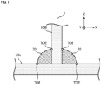
- FIG. 1 and FIG. 2 are explanatory views schematically illustrating an enlarged part of an example of the welded member according to this embodiment.
- FIG. 3 is a schematic view for explaining the example of the welded member according to this embodiment.
- the welded member according to this embodiment is a welded member made by connecting a Ni plated steel sheet and another steel sheet via a welded part. More specifically, the welded member is manufactured by welding a Ni plated steel sheet which will be explained in detail below with a Ni welding wire containing 90 mass% or more of Ni and having a total content of S and C of 0.1 mass% or less.
- a welded member 1 has Ni plated steel sheets 10A, 10B, and a welded part 20.
- Ni plated steel sheets 10A, 10B are also called Ni plated steel sheets 10.
- a mode in which the Ni plated steel sheets are welded together will be explained, but not limited to this mode, at least one of the steel sheets constituting the welded member only needs to be the Ni plated steel sheet 10 explained below.
- the welded member 1 includes the Ni plated steel sheets 10, the welded part 20, and an alloy part 30.
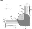
- the Ni plated steel sheet 10 is a plated steel sheet having a Ni plating layer 103 and a Fe-Ni diffusion alloy layer 105 formed on the surface of a steel sheet 101 which is a base sheet as schematically illustrated in FIG. 2 .
- the Ni plated steel sheet 10 will be explained again in detail below.
- the welded part 20 is also called a weld bead part, and is a portion formed by welding the Ni plated steel sheets 10 with a Ni alloy or pure Ni welding wire.
- the welding causes interdiffusion of constituent elements between the Ni plating layer 103 and the Fe-Ni diffusion alloy layer 105 of the Ni plated steel sheet 10 and the Ni alloy or pure Ni welding wire to form the welded part 20.
- parts of the Ni plating layer 103, the Fe-Ni diffusion alloy layer 105, and the steel sheet 101 of the base material change to form into the alloy part 30. Note that the welded part 20 and the alloy part 30 can be discriminated by cross-section observation.
- a portion which has not been subjected to welding for example, a portion in the Ni plated steel sheet 10 away by 5 mm or more from a later-explained toe
- a non-welded part a portion which has not been subjected to welding (for example, a portion in the Ni plated steel sheet 10 away by 5 mm or more from a later-explained toe) in the welded member 1 according to this embodiment.
- the Ni plated steel sheet 10 according to this embodiment (more specifically, the Ni plated steel sheet 10 corresponding to the non-welded part) has the steel sheet 101 which is the base sheet, the Ni plating layer 103 located on the steel sheet 101, and the Fe-Ni diffusion alloy layer 105 located between the steel sheet 101 and the Ni plating layer 103 as schematically illustrated in FIG. 2 .
- the steel sheet 101 to be used as the base sheet of the Ni plated steel sheet 10 according to this embodiment is not particularly limited, but various steel sheets can be used according to the mechanical strength or the like required for the Ni plated steel sheet 10.
- the steel sheet 101 include various types of steel such as various types of A1 killed steel, ultralow carbon steel containing Ti, Nb, or the like, and high-strength steel further containing a strengthening element such as P, Si, Mn in the ultralow carbon steel.
- the thickness of the steel sheet 101 is not particularly limited, but may be appropriately set according to the mechanical strength or the like required for the Ni plated steel sheet 10.
- the Fe-Ni diffusion alloy layer 105 means a portion having a Ni concentration, which is obtained through analysis only of metal elements when performing a cross-sectional analysis by a scanning electron microscope (SEM) equipped with an energy dispersive X-ray analyzer (EDS) (hereinafter, abbreviated as a SEM-EDS) under the following conditions, in a range of 30 mass%. or more and less than 70 mass%.
- SEM-EDS energy dispersive X-ray analyzer
- the Ni plating layer 103 according to this embodiment means a portion having a Ni concentration, which is obtained through the analysis only of metal elements when performing the cross-sectional analysis by the SEM-EDS under the following conditions, of 70 mass% or more.
- the measurement conditions of the SEM-EDS in the above analysis only need to be, for example, an acceleration voltage of 15.0 kV, an irradiation current of 0.00564 nA, and an energy range of 0 to 20 keV.
- a Ni deposition amount of the Ni plated steel sheet 10 (more specifically, a total Ni deposition amount of the Ni plating layer 103 and the Fe-Ni diffusion alloy layer 105) is preferably 20 to 100 g/m 2 per side in terms of metal.
- the Ni deposition amount is less than 20 g/m 2 , the corrosion resistance required for the welded member 1 cannot be sufficiently exhibited in some cases.
- the Ni deposition amount of the Ni plated steel sheet 10 is more preferably 30 g/m 2 or more, and furthermore preferably 40 g/m 2 or more.
- the Ni deposition amount of the Ni plated steel sheet 10 is more than 100 g/m 2 , the corrosion resistance of the Ni plated steel sheet 10 is saturated, whereas the cost when applying the Ni plating tends to increase.
- the Ni deposition amount of the Ni plated steel sheet 10 is more preferably 90 g/m 2 or less, and furthermore preferably 60 g/m 2 or less.
- the Ni deposition amount can be measured as follows.
- a 10 mm square area toward the non-welded part side using a position 5 mm from the toe illustrated in FIG. 2 toward the non-welded part (namely, in a direction away from the welded part 20) as a starting point is cut in the thickness direction by a high-speed precision cutting machine, and used as a specimen for measurement of the Ni deposition amount.
- the specimen thus cut out is sealed on a single side with Teflon tape, and then polished from the rear side in a manner to leave the Ni plating layer and the Fe-Ni diffusion alloy layer on the sealed side.
- the specimen after the polishing is immersed in a 35% hydrochloric acid until the base sheet can be removed, to obtain a sample.
- the obtained sample is subjected to measurement by ICP (inductively Coupled Plasma) emission spectrometry (for example, ICPS-8100 manufactured by SHIMADZU CORPORATION), whereby the Ni amount is quantified and converted to a deposition amount by g/m 2 and the Ni deposition amount is obtained.
- ICP inductively Coupled Plasma
- ICPS-8100 manufactured by SHIMADZU CORPORATION
- the Ni plating layer 103 (the Ni plating layer 103 corresponding to the non-welded part) is not particularly limited as long as it is Ni plating having a Ni concentration of 70 mass% or more, and various types of Ni plating including various types of electric Ni plating and non-electrolytic Ni plating can be applied.
- the Ni concentration in the Ni plating layer 103 is more preferably 80 mass% or more, and furthermore preferable 90 mass% or more.
- a total concentration of S (sulfur) and C (carbon) in the Ni plating layer 103 is less than 20 ppm.
- the above “toe” is a position prescribed by JIS Z3001 (2016), and corresponds to a portion where the surface of a base material (namely, a steel sheet which is a base sheet) and the surface of a weld bead (namely, the welded part 20) intersect. In this embodiment, it corresponds to a portion where the surface of the Ni plating layer 103 in the Ni plated steel sheet 10 and the surface of the welded part 20 intersect.
- the position of the "toe” is schematically illustrated in FIG. 1 and FIG. 2 .
- the toe in the welded member 1 illustrated in FIG. 1 and FIG. 2 can be regarded as a line segment extending in a Y-axis direction.
- the total concentration of S and C is set to less than 20 ppm in the Ni plating layer 103 according to this embodiment (specifically, the Ni plating layer 103 at the non-welded part).
- the concentration analysis of S and C in the Ni plated steel sheet is performed for the Ni plated steel sheet 10 being the non-welded part using EMIA-920V2 which is a carbon and sulfur analyzer manufactured by HORIBA, Ltd. More specifically, the Ni plated steel sheet is sealed on a single side with Teflon tape, and then polished from the rear side in a manner to leave the Ni plating layer on the sealed side. The specimen after the polishing is immersed in a 35% hydrochloric acid until the base sheet and the Fe-Ni diffusion alloy layer can be removed, to obtain Ni foil. The seal is peeled off and the resultant Ni foil is made into a diameter of 2 to 3 mm, put into a ceramics crucible, and baked in an oxygen flow. The generated CO 2 , CO, SO 2 gasses are detected by an infrared detector, and results of conversion to carbon and sulfur based on the detection results are regarded as concentrations of S and C in the Ni plated steel sheet.
- EMIA-920V2 is a carbon and sulfur
- H which is a plating co-deposit in the as-plated Ni plating layer by an annealing treatment prior to the welding.
- the annealing treatment will be explained again in more detail below.
- Examples of the above-explained Ni plating include pure Ni plating.
- an average thickness (hereinafter, simply referred to as a thickness) of the Fe-Ni diffusion alloy layer 105 is 0.5 to 1.5 ⁇ m, and an average total thickness (hereinafter, simply referred to as a thickness) of the Ni plating layer 103 and the Fe-Ni diffusion alloy layer 105 is 2.7 to 14.0 ⁇ m.
- the average thickness of the Fe-Ni diffusion alloy layer 105 is preferably 0.7 ⁇ m or more or 1.0 ⁇ m or more, and preferably 1.3 ⁇ m or less.
- the average total thickness of the Ni plating layer 103 and the Fe-Ni diffusion alloy layer 105 is preferably 3.0 ⁇ m or more or 4.0 ⁇ m or more, and preferably 12.5 ⁇ m or less or 10.0 ⁇ m or less.
- the Ni plated steel sheet 10 according to this embodiment can realize the corrosion resistance at a level at which sufficient corrosion resistance can be maintained even under high temperature and alkali conditions.
- an average thickness of the Ni plating layer 103 is 1.7 ⁇ m or more, overdiffusion of Fe to the surface layer can be prevented in and around the welded part during welding.
- the thickness of the Fe-Ni diffusion alloy layer 105 falls within the above range, co-deposition of C and S during welding can be prevented.
- the thickness of the Fe-Ni diffusion alloy layer 105 is 1.5 ⁇ m or more, the plating adhesiveness lowers to deteriorate the corrosion resistance.
- the thickness of the Ni plating layer 103 and the thickness of the Fe-Ni diffusion alloy layer 105 are measured in cross-sectional view of cutting in the thickness direction at a position 5 mm from the toe toward the non-welded part side in surface view.
- a 10 mm square area toward the non-welded part side using a position 5 mm from the toe toward the non-welded part side as a starting point in surface view is cut in the thickness direction, and used as a specimen for cross-section observation.
- the specimen is embedded in a resin and polished to obtain a cross section as an observational object, and the cross section is observed by the SEM-EDS for measurement.
- elemental analysis is performed in the cross section while focusing only on metal elements, and the thickness of an area where the obtained Ni concentration is within a range of 30 mass% or more and less than 70 mass% (namely, the Fe-Ni diffusion alloy layer 105) and the thickness of an area where the obtained Ni concentration is 70 mass% or more (namely, the Ni plating layer 103) are measured.
- This measurement is performed at arbitrary ten locations within the cross section.
- An average value of remaining eight measured values after excluding the maximum value and the minimum value of the obtained measured values is regarded as the thickness of each of the Fe-Ni diffusion alloy layer 105 and the Ni plating layer 103.
- the welded part 20 is preferably a Ni alloy having a Ni concentration (more specifically, an average concentration of Ni) of 70 mass% or more.
- the welded part 20 is formed by performing welding by a welding method explained in detail below using a welding wire of Ni alloy or pure Ni.
- the welded part 20 is a Ni alloy having a Ni concentration of 70 mass% or more, the possibility of ensuring the corrosion resistance at a welded point where the Ni plating layer 103 disappears increases.
- the measurement of the Ni concentration of the welded part 20 is performed as follows. First, the cross section obtained by cutting the welded part 20 at an X-Z plane illustrated in FIG. 1 is embedded and polished, and subjected to cross-section observation. The concentration measurement is performed at arbitrary ten locations within the cross section. An average value of remaining eight measured values after excluding the maximum value and the minimum value of the obtained measured values is regarded the average concentration of Ni.
- the Ni concentration of the welded part 20 is preferably 90 mass% or more.
- the welded part 20 has the Ni concentration and thereby can surely ensure the corrosion resistance at the welded point.
- the welded member 1 has a Ni concentration of 70 mass% or more and a Fe concentration of 30 mass% or less in the surface layer of each of the toe prescribed by JIS Z3001 (2016), the Ni plated steel sheet 10, and the welded part 20.
- the position of the Ni plated steel sheet whose Ni concentration is measured is an area of the Ni plated steel sheet 10 at a distance from the toe toward the non-welded part side (namely, in a direction away from the welded part 20) of 10 ⁇ m or more and 1 mm or less (hereinafter, this area is also referred to as a toe near area).
- the welding causes thermal diffusion of an element Fe derived from the Ni plated steel sheet.
- the proportion of Fe diffused to the surface layer of each of the toe, the toe near area, and the welded part 20 is suppressed to 30 mass% or less.
- the surface layer of each of the toe, the toe near area, and the welded part 20 has the above Ni concentration and Fe concentration, it is possible to realize the corrosion resistance at a level at which sufficient corrosion resistance can be maintained even under high temperature and alkali environments.
- This configuration is effective particularly for maintaining the corrosion resistance of the Ni plated steel sheet at the welded part or the toe part or near the toe.
- the Ni concentration in the surface layer of each of the toe, the toe near area, and the welded part 20 is preferably 90 mass% or more. Further, the Fe concentration in the surface layer of each of the toe, the toe near area, and the welded part 20 is preferably 10 mass% or less.
- an oxide coating film produced by a reaction with oxygen in the atmosphere or dirt such as fats and oil may adhere to the surfaces of the toe, the toe near area, and the welded part 20. Therefore, the above Ni concentration and Fe concentration are desirably measured in a state where the oxide coating film, dirt, and so on do not exist. From this viewpoint, the above Ni concentration and Fe concentration are assumed to be concentrations when performing element concentration measurement by Auger spectroscopy, in a field of view where the surfaces of the toe, the toe near area, and the welded part 20 can be observed, on faces obtained by removing the surfaces in the thickness direction from the surfaces by Ar ion etching until the oxygen concentration becomes 25 mass% or less.
- a range to be removed by the Ar ion etching preferably has a depth of within 1 ⁇ m from the surface of each of the toe, the toe near area, and the welded part 20.
- the measurement conditions of the element concentration measurement by the Auger spectroscopy only need to be, for example, an acceleration voltage of 15 kV and an irradiation current of 10 nA.
- the element concentration measurement (measurement only of metal elements) by the Auger spectroscopy is performed under the measurement conditions at arbitrary five locations within the observation plane for the toe near area and the welded part 20 and at arbitrary five locations on an intersection line of the welded part 20 and the Ni plated steel sheet 10 within the observation plane for the toe.
- An average of three measured values excluding the maximum value and the minimum value of the obtained five measured values of each of the Ni concentration and Fe concentration is regarded as each of the Ni concentration and the Fe concentration.
- H which is a plating deposit vaporizes near the toe to form a pinhole, causing deterioration in the corrosion resistance. It has been further found that when Ni plating containing S and C is applied to the plating layer as Ni plating, S and C co-deposited by welding also vaporize to be more likely to form pinholes.
- a smaller number of pinholes each having a circle-equivalent diameter of 10 ⁇ m or more is more preferable because the pinhole having a circle-equivalent diameter of 10 ⁇ m or more becomes a starting point of red rust generation.
- the present inventors have conceived limiting the total concentration of S and C in the Ni plating layer 103 to 20 ppm or less and performing the annealing treatment on the Ni plated steel sheet 10 prior to the welding. This makes it possible to eliminate the existence of S and C which can vaporize, and makes it possible to make H which is a plating co-deposit vaporize during the annealing treatment. Further, the pinhole formed by vaporization of H during the annealing treatment is repaired under the heating environment for the annealing treatment.
- the average number of pinholes each having a circle-equivalent diameter of 10 ⁇ m or more which can be generated as a result of welding is extremely low in the welded member 1 according to this embodiment. Also from this viewpoint, the welded member 1 according to this embodiment has excellent corrosion resistance.
- an area having a length of 10 cm along an extending direction in an area at a distance of up to 1 mm from the toe toward the non-welded part side on the surface of the Ni plating layer 103 is regarded as a rectangular area R.
- a plurality of such rectangular areas R can be assumed in the welded member 1 according to this embodiment.
- the average number of pinholes each having a circle-equivalent diameter of 10 ⁇ m or more existing in the rectangular areas R. at arbitrary five adjacent locations is three or less. This shows that the welded member 1 according to this embodiment has excellent corrosion resistance even near the welded part 20.
- the average number of pinholes each having a circle-equivalent diameter of 10 ⁇ m or more as above can be counted by observation with the SEM. The observation is performed at the above five locations and the number of pinholes each having a circle-equivalent diameter of 10 ⁇ m or more is counted in each of the rectangular areas R. The average of three counted values excluding the maximum value and the minimum value of obtained five counted values is regarded as the average number of pinholes.
- the welded member 1 according to this embodiment has been explained in detail with reference to FIG. 1 to FIG. 3 .
- the welded member according to this embodiment is manufactured by manufacturing a Ni plated steel sheet having a Fe-Ni diffusion alloy layer and then welding the Ni plated steel sheet using a Ni welding wire.
- the fusion bonding of the Ni plated steel sheet having the Fe-Ni diffusion alloy layer by using the Ni welding wire is not conventionally performed.
- the welded member according to this embodiment cannot be obtained, and therefore it is important to bring the thickness of the Fe-Ni diffusion alloy layer into a desired state and then control the heat input amount at welding.
- the Ni plated steel sheet is manufactured by performing Ni plating to achieve a desired deposition amount on the surface of the steel sheet which is the base sheet using a predetermined Ni plating bath and then performing an annealing treatment.
- Ni plating bath various types of Ni plating baths adjusted so that the total concentration of S and C is less than 20 ppm.
- the Ni plating bath include a Watts bath, a nickel sulfate bath, a nickel chloride bath, and so on.
- the electric Ni plating is performed so that the plating deposition amount becomes 15 to 100 g/m 2 in terms of metal.
- the plating deposition amount can be adjusted by controlling the current density, energization time, or the like during the electric plating.
- Ni plated steel sheet which has the Fe-Ni diffusion alloy layer and the Ni plating layer and is suppressed in generation of pinholes each having a circle-equivalent diameter of 10 ⁇ m or more even when welding.
- a holding temperature for example, of 600 to 850°C for 5 to 60 seconds. This makes it possible to more surely form a desired Fe-Ni diffusion alloy layer and more surely vaporize H which is a plating co-deposit.
- the holding temperature is more preferably 700 to 850°C, and the holding time is more preferably 20 to 60 seconds.
- a temperature increasing rate from room temperature to the holding temperature is preferably, for example, 5 to 100 °C/sec. Further, it is preferable to cool the Ni plated steel sheet down to 200°C by N 2 gas cooling after a lapse of the desired holding temperature, and then take it out to the air atmosphere.
- annealing treatment for example, under environments of a 2% H 2 -N 2 atmosphere and a dew point of -60°C.
- the Ni plated steel sheet having the Fe-Ni diffusion alloy layer manufactured as above is welded using a welding wire of a Ni alloy containing 90 mass% or more of Ni or pure Ni containing 99 mass% or more of Ni, which has a desired Ni concentration.
- the welding method laser welding or arc welding can be used.
- the welded member 1 according to this embodiment a mode in which the Ni plated steel sheet and the Ni sheet are welded together can be applied, but a mode in which the Ni plated steel sheets are welded together is preferable from viewpoint of cost reduction.
- the spot welding there is spot welding as one welding method, but at least in the case of using the spot welding as the method of welding the Ni plated steel sheets, the welded part having a Ni concentration of 70 mass% or more focused in this embodiment cannot be realized.
- the laser welding fiber laser, disk leather, and semiconductor laser are preferable.
- the use of a low heat input welding process such as Cold Metal Transfer (CMT (registered trademark)) is more preferable in order to bring the diffusion of Fe by the heat input at the welding into a desired state.
- Synchro-feed (registered trademark) GMA welding and S-AWP (Super Active Wire Feed Process) welding are also preferable. These are different in name depending on the welder manufacturer but are welding methods equivalent to CMT.
- the laser welding it is preferable to use a welding wire having a diameter of 0.6 mm to 1.6 mm and adjust the beam so that the beam has a laser beam diameter of 0.8 to 3.5 times the welding wire diameter.
- it is preferable to perform welding by supplying the welding wire to a laser irradiation part at a speed of 0.6 to 4.0 times the welding speed.
- the output and speed of the laser only need to be appropriately adjusted.
- a welding wire having a diameter of 0.6 mm to 1.6 mm.
- an argon gas or a shielding gas made by adding 3% or less of a carbon dioxide gas or oxygen to argon.
- the flow rate of the shielding gas it is preferable to 10 to 50 L/min.
- the current and the welding speed it is preferable to adjust the current in a range of 60 to 250 A and the welding speed in a range of 0.2 to 1.8 m/min.
- TIG welding or plasma welding using the Ni wire may also be used.
- melt welding is performed by controlling the heat input amount to an appropriate value using the Ni wire while appropriately controlling the thicknesses of the Ni plating layer and the Fe-Ni diffusion alloy layer. This can set the Ni concentration in the surface layer of each of the toe, the toe near area, and the welded part in the welded member to an appropriate value (70 mass% or more).
- the welded member according to this embodiment is manufactured as above.
- the welded member according to the present invention will be concretely explained while illustrating examples and comparative examples. Note that the examples below are merely examples of the welded member according to the present invention and the welded member according to the present invention is not limited to the following examples.
- B-added Al-killed steel (sheet thickness of 1 mm) was prepared as the steel sheet being the base sheet.
- a Watts bath having a bath composition listed in Table 1 below was prepared.
- a bright plating bath with 0.2 /L of butynediol as a carbon source and 2 g/L of saccharin Na as a sulfur source added to the Watts bath listed in Table 1 below was prepared for comparison.
- the current density at electroplating was set to 20 A/dm 2 , and a desired plating deposition amount was realized by changing the energization time.
- an annealing treatment was carried out in a 2% H 2 -N 2 atmosphere and under an environment of a dew point of -60°C.
- the Ni plated steel sheet was heated from room temperature to the predetermined holding temperature at a temperature increasing rate of 25 °C/sec, the holding temperature was held for a predetermined time, and then the Ni plated steel sheet was cooled down to 200°C by N 2 gas cooling and taken out to the air atmosphere.
- the holding temperature and the holding time are as listed in Table 6 below.
- the obtained Ni plated steel sheet was cut into a size of 150 mm ⁇ 50 mm and used for welding.
- the atmosphere of the welding place was set to 10°C and 20% RH.
- a Cu manufacturing jig of 100 mm ⁇ 200 mm and a thickness of 20 mm and a Cu manufacturing jig of 30 mm ⁇ 200 mm and a thickness of 20 mm with a cutout of 5 mm as schematically illustrated in FIG. 4 were cooled to -20°C with dry ice, and the Ni plated steel sheet was fixed to the manufacturing jigs and subjected to fillet welding using a Ni wire having a diameter of 1.2 mm.
- the Ni concentration and Fe concentration in the surface layer of each of the toe, the toe near area of the Ni plated steel sheet (an area at a distance from the toe toward the non-welded part side of 10 ⁇ m or more and 1 mm or less), and the welded part were measured by the Auger spectroscopy.
- the Auger spectrometer used is JAMP-9500F manufactured by JEOL Ltd. Note that in this concentration measurement, faces obtained by removing the surfaces of the toe, the Ni plated steel sheet, and the welded part by Ar ion etching until the oxygen concentration became 25 mass% or less were regarded as measuring surfaces. The removal amount by the Ar ion etching was within 1 ⁇ m in the thickness direction in any specimen.
- the element concentration measurement (measurement only of metal elements) by the Auger spectroscopy was carried out at arbitrary five points within the observation plane (arbitrary five points on the intersection line of the welded part and the Ni plated steel sheet within the observation plane in the case of the toe) at the measurement conditions of an acceleration voltage of 15 kV and an irradiation current of 10 nA.
- An average of three measured values excluding the maximum value and the minimum value of the obtained five measured values of each of the Ni concentration and the Fe concentration was regarded as each of the Ni concentration and the Fe concentration.
- a 10 mm square area toward the non-welded part side using a position 5 mm from the toe in FIG. 2 toward the non-welded part side as a starting point was cut in the thickness direction using a high-speed precision cutting machine, and used as a specimen for measurement of the Ni deposition amount.
- the specimen thus cut out was sealed on a single side with Teflon tape, and then polished from the rear side in a manner to leave the Ni plating layer and the Fe-Ni diffusion alloy layer on the sealed side.
- the specimen after the polishing was immersed in a 35% hydrochloric acid until the base sheet was removed, to obtain a sample.
- the obtained sample was subjected to measurement by ICP (Inductively Coupled Plasma) emission spectrometry (for example, ICPS-8100 manufactured by SHIMADZU CORPORATION), whereby the Ni amount was quantified and converted to a deposition amount by g/m 2 and the Ni deposition amount was obtained.
- ICP Inductively Coupled Plasma
- Each obtained welded member was in the thickness direction cut at a position 5 mm from the toe in FIG. 2 toward the non-welded part side using a high-speed precision cutting machine.
- a 10 mm square area toward the non-welded part side using a position 5 mm from the toe toward the non-welded part side as a starting point in surface view was cut in the thickness direction.
- a cross-section observation specimen and a surface observation specimen were cut out and subjected to analysis.
- a SEM JSM-7000F manufactured by JEOL Ltd.
- the detection limit of the element concentration in the SEM-EDS analysis used for the confirmation of the Ni plating layer is 1500 to 2000 ppm, and therefore the concentration analysis of S and C in the Ni plated steel sheet was carried out for the specimens before embedding, using EMIA-920V2 being a carbon and sulfur analyzer manufactured by HORIBA, Ltd. More specifically, the Ni plated steel sheet was sealed on a single side with Teflon tape, and then polished from the rear side in a manner to leave the Ni plating layer on the sealed side. The specimen after the polishing was immersed in a 35% hydrochloric acid until the base sheet and the Fe-Ni diffusion alloy layer were removed, to obtain Ni foil.
- the seal was removed and the obtained Ni foil was formed into a diameter of 2 to 3 mm and put into a ceramics crucible and baked in an oxygen flow.
- the generated CO 2 , CO, SO 2 gasses were detected by an infrared detector, and converted to carbon and sulfur.
- a detection lower limit of each element by the measurement method is C: 3 ppm and S: 1 ppm.
- a concentration equal to or lower than the detection lower limit was regarded as CK, and a concentration of 20 ppm or more was regarded as NG.
- the specimen for the surface observation a portion of the cross-section observation specimen located at a shortest distance cut out by a length of 50 cm was used. The cut-out portion was cut in units of 10 cm so that five specimens of the rectangular area R as schematically illustrated in FIG. 3 were prepared. Each obtained specimen was subjected to ultrasonic cleaning in acetone for 60 seconds, and subjected to observation. A range of the toe 1 mm width ⁇ 10 cm (rectangular area R as illustrated in FIG. 3 ) was observed under a SEM. For each specimen, the presence or absence of pinholes each having a circle-equivalent diameter of 10 ⁇ m or more was observed, and the average number was calculated following the above-explained method. A case where the obtained average number was three or less was regarded as OK, and a case where the obtained average number was more than four was regarded as NG.
- the surface observation specimen after the surface observation was used.
- an end surface and a rear surface were paint-sealed, and the welded part was evaluated by a 35°C, 5%-salt spray test for three hours.
- the toe was observed, and the number of occurrences of red rust per range of 1 mm width ⁇ 10 cm was counted.
- An average of three counted values excluding the maximum value and the minimum value of obtained five counted values was calculated and regarded as the frequency of the red rust occurrence.
- the welded members corresponding to examples of the present invention exhibit excellent corrosion resistance.
- the welded members corresponding to the comparative examples of the present invention are inferior in corrosion resistance.
Landscapes
- Engineering & Computer Science (AREA)
- Chemical & Material Sciences (AREA)
- Physics & Mathematics (AREA)
- Mechanical Engineering (AREA)
- Materials Engineering (AREA)
- Optics & Photonics (AREA)
- Organic Chemistry (AREA)
- Metallurgy (AREA)
- Electrochemistry (AREA)
- Plasma & Fusion (AREA)
- Chemical Kinetics & Catalysis (AREA)
- Electroplating Methods And Accessories (AREA)
- Arc Welding In General (AREA)
- Laser Beam Processing (AREA)
- Glass Compositions (AREA)
- Nonmetallic Welding Materials (AREA)
Applications Claiming Priority (2)
| Application Number | Priority Date | Filing Date | Title |
|---|---|---|---|
| JP2021184683 | 2021-11-12 | ||
| PCT/JP2022/042145 WO2023085410A1 (ja) | 2021-11-12 | 2022-11-11 | 溶接部材 |
Publications (2)
| Publication Number | Publication Date |
|---|---|
| EP4403289A1 true EP4403289A1 (de) | 2024-07-24 |
| EP4403289A4 EP4403289A4 (de) | 2025-01-15 |
Family
ID=86335845
Family Applications (1)
| Application Number | Title | Priority Date | Filing Date |
|---|---|---|---|
| EP22892908.9A Pending EP4403289A4 (de) | 2021-11-12 | 2022-11-11 | Geschweisstes element |
Country Status (6)
| Country | Link |
|---|---|
| US (1) | US12240199B2 (de) |
| EP (1) | EP4403289A4 (de) |
| JP (1) | JP7381985B2 (de) |
| CN (1) | CN118251287B (de) |
| TW (1) | TWI818801B (de) |
| WO (1) | WO2023085410A1 (de) |
Families Citing this family (1)
| Publication number | Priority date | Publication date | Assignee | Title |
|---|---|---|---|---|
| TWI905750B (zh) * | 2024-05-10 | 2025-11-21 | 日商日本製鐵股份有限公司 | 熔接接頭 |
Family Cites Families (23)
| Publication number | Priority date | Publication date | Assignee | Title |
|---|---|---|---|---|
| JP2651448B2 (ja) * | 1988-07-06 | 1997-09-10 | 臼井国際産業株式会社 | 排気ガス浄化用触媒を担持するための金属製担持母体及びその製造方法 |
| JP3047402B2 (ja) * | 1988-08-13 | 2000-05-29 | 臼井国際産業株式会社 | 薄肉鋼板及びその製造方 |
| KR100352644B1 (ko) * | 2000-07-28 | 2002-09-12 | 고려용접봉 주식회사 | 내응력 부식균열, 내공식 성능 및 용접성이 우수한 2상스테인레스강용 플럭스 코어드 와이어 |
| US6730876B2 (en) * | 2001-05-29 | 2004-05-04 | U.S. Pipe And Foundry Company | Highly ductile reduced imperfection weld for ductile iron and method for producing same |
| JP4280181B2 (ja) * | 2004-03-09 | 2009-06-17 | 新日本製鐵株式会社 | 溶接性、密着性、耐食性に優れた溶接缶用鋼板 |
| JP5098217B2 (ja) * | 2005-09-28 | 2012-12-12 | 新日鐵住金株式会社 | 溶接部の耐食性および耐亜鉛脆化割れ性に優れた亜鉛めっき鋼板の溶接継手並びにその製造方法 |
| KR100774155B1 (ko) * | 2006-10-20 | 2007-11-07 | 고려용접봉 주식회사 | 이상 스테인리스강 용접용 플럭스 코어드 와이어와 그제조방법 |
| JP4377955B2 (ja) * | 2007-12-27 | 2009-12-02 | 新日本製鐵株式会社 | 亜鉛めっき鋼板溶接用ステンレス鋼フラックス入り溶接ワイヤおよびこれを用いた亜鉛めっき鋼板のアーク溶接方法 |
| US20120009464A1 (en) * | 2009-03-31 | 2012-01-12 | Makoto Nakazawa | Material for metal case of secondary battery using non-aqueous electrolyte, metal case, secondary battery, and producing method of material for metal case |
| CN102596488B (zh) * | 2009-10-26 | 2013-09-18 | 株式会社新王材料 | 铝接合合金、具有由该合金形成的接合合金层的覆层材料和铝接合复合材料 |
| EP2538472B1 (de) * | 2010-02-15 | 2017-03-29 | Hitachi Metals, Ltd. | Verkleidungsmaterial für zuleitungen und verfahren zum schweissen von verkleidungsmaterial für zuleitungen |
| WO2012153728A1 (ja) * | 2011-05-10 | 2012-11-15 | Jx日鉱日石金属株式会社 | Niめっき金属板、溶接構造体、及び電池用材料の製造方法 |
| JP6023513B2 (ja) * | 2012-08-29 | 2016-11-09 | 東洋鋼鈑株式会社 | 電池容器用表面処理鋼板、電池容器および電池 |
| JP2014059954A (ja) | 2012-09-14 | 2014-04-03 | Skk Corp | 角型電池缶及びその製造方法 |
| CN103343367A (zh) * | 2013-07-12 | 2013-10-09 | 深圳市中金高能电池材料有限公司 | 镀镍钢带及其制备方法 |
| JP5997393B2 (ja) * | 2013-09-27 | 2016-09-28 | 京セラ株式会社 | 蓋体、パッケージおよび電子装置 |
| US10052721B2 (en) * | 2014-09-17 | 2018-08-21 | Magna International Inc. | Method of laser welding coated steel sheets with addition of alloying elements |
| CN107710446B (zh) * | 2015-07-07 | 2021-02-12 | 日本制铁株式会社 | 非水电解液二次电池壳体用钢板和非水电解液二次电池壳体 |
| JP6623663B2 (ja) * | 2015-10-13 | 2019-12-25 | 日本製鉄株式会社 | 端面を被覆したNiめっき鋼箔及び電池導電部材、Niめっき鋼箔の製造方法 |
| KR20230078836A (ko) * | 2015-12-03 | 2023-06-02 | 도요 고한 가부시키가이샤 | 전지 용기용 표면 처리 강판 |
| CN106270879A (zh) * | 2016-09-29 | 2017-01-04 | 哈尔滨工业大学(威海) | 一种镀层辅助调控的镁和钢异种材料激光熔钎焊方法 |
| US11535916B2 (en) * | 2017-12-05 | 2022-12-27 | Nippon Steel Corporation | Aluminum-based plated steel sheet, method of manufacturing aluminum-based plated steel sheet, and method of manufacturing component for vehicle |
| MX2021010815A (es) * | 2019-04-19 | 2021-10-01 | Nippon Steel Corp | Lamina de acero chapada. |
-
2022
- 2022-11-11 US US18/702,221 patent/US12240199B2/en active Active
- 2022-11-11 EP EP22892908.9A patent/EP4403289A4/de active Pending
- 2022-11-11 CN CN202280074722.4A patent/CN118251287B/zh active Active
- 2022-11-11 WO PCT/JP2022/042145 patent/WO2023085410A1/ja not_active Ceased
- 2022-11-11 JP JP2023539371A patent/JP7381985B2/ja active Active
- 2022-11-14 TW TW111143354A patent/TWI818801B/zh active
Also Published As
| Publication number | Publication date |
|---|---|
| US12240199B2 (en) | 2025-03-04 |
| WO2023085410A1 (ja) | 2023-05-19 |
| CN118251287B (zh) | 2025-01-10 |
| CN118251287A (zh) | 2024-06-25 |
| EP4403289A4 (de) | 2025-01-15 |
| JP7381985B2 (ja) | 2023-11-16 |
| JPWO2023085410A1 (de) | 2023-05-19 |
| TW202330957A (zh) | 2023-08-01 |
| US20240326381A1 (en) | 2024-10-03 |
| TWI818801B (zh) | 2023-10-11 |
Similar Documents
| Publication | Publication Date | Title |
|---|---|---|
| EP1738854B1 (de) | Verbundener körper aus verschiedenen materialien umfassend stahlmaterial und aluminiummaterial und verbindungsverfahren dafür | |
| EP1728578B1 (de) | Stahlblech für ungleichartige Materialien durch Schweissen zu Aluminiummaterial verbunden und verbundener Körper aus ungleichartigen Materialien | |
| US11577346B2 (en) | Wire for electroslag welding, flux for electroslag welding and welded joint | |
| EP3513901B1 (de) | Vorrichtung für stromloses schweissen, flussmittel für elektroloses schweissen und schweissverbindung | |
| EP3461579B1 (de) | Verfahren zur herstellung von verkleidungsmaterial | |
| JP7394025B2 (ja) | 電気・電子機器用部品 | |
| EP2610361A1 (de) | Fülldraht für Kohlenstoffstahl und Verfahren zum Lichtbogenschweißen | |
| EP4403289A1 (de) | Geschweisstes element | |
| EP3587018A1 (de) | Verfahren zum mig-löten, verfahren zur herstellung eines überlappstosses und überlappstoss | |
| JPH08218137A (ja) | レーザー溶接性に優れた銅または銅合金部材 | |
| Dziekońska et al. | Microstructure and properties of dissimilar joints of AISI 430 steel with Inconel 625 obtained by electron beam welding | |
| EP4306255A1 (de) | Lichtbogenschweissverbindung und lichtbogenschweissverfahren | |
| KR101205332B1 (ko) | 용접용 와이어 | |
| US20200164472A1 (en) | Wire for welding different types of materials and method of manufacturing the same | |
| JP2012045555A (ja) | スポット溶接用電極 | |
| Hsu et al. | Impurity-induced unusual microstructural evolution and mechanical property in Sn/Cu solder joints | |
| JP2023084041A (ja) | 溶接方法、溶接金属、溶接継手の製造方法及び溶接継手 | |
| JP2003342784A (ja) | すず−銀−銅はんだ合金の形成方法並びに当該合金を使用する鉛フリーバンプおよび半導体素子の製造方法 | |
| JP7640927B1 (ja) | 表面処理鋼板、表面処理鋼板の製造方法、及び電池部品の製造方法 | |
| JP7394024B2 (ja) | 電気・電子機器用部品 | |
| US11986902B2 (en) | Welded product and method of producing welded product | |
| US20220001481A1 (en) | Method for welding a titanium component with a titanium nitride coating | |
| JPH0919771A (ja) | プラズマアーク溶接トーチ用ノズル | |
| CN120418481A (zh) | 镀镍金属材料 | |
| JP2021186866A (ja) | 電気・電子機器用部品 |
Legal Events
| Date | Code | Title | Description |
|---|---|---|---|
| STAA | Information on the status of an ep patent application or granted ep patent |
Free format text: STATUS: THE INTERNATIONAL PUBLICATION HAS BEEN MADE |
|
| PUAI | Public reference made under article 153(3) epc to a published international application that has entered the european phase |
Free format text: ORIGINAL CODE: 0009012 |
|
| STAA | Information on the status of an ep patent application or granted ep patent |
Free format text: STATUS: REQUEST FOR EXAMINATION WAS MADE |
|
| 17P | Request for examination filed |
Effective date: 20240416 |
|
| AK | Designated contracting states |
Kind code of ref document: A1 Designated state(s): AL AT BE BG CH CY CZ DE DK EE ES FI FR GB GR HR HU IE IS IT LI LT LU LV MC ME MK MT NL NO PL PT RO RS SE SI SK SM TR |
|
| A4 | Supplementary search report drawn up and despatched |
Effective date: 20241216 |
|
| RIC1 | Information provided on ipc code assigned before grant |
Ipc: B23K 35/02 20060101ALI20241210BHEP Ipc: C25D 7/06 20060101ALI20241210BHEP Ipc: B23K 35/30 20060101ALI20241210BHEP Ipc: C25D 7/02 20060101ALI20241210BHEP Ipc: C25D 5/36 20060101ALI20241210BHEP Ipc: C25D 3/12 20060101ALI20241210BHEP Ipc: B23K 11/11 20060101ALI20241210BHEP Ipc: B32B 15/01 20060101ALI20241210BHEP Ipc: C25D 5/50 20060101ALI20241210BHEP Ipc: C25D 5/26 20060101ALI20241210BHEP Ipc: B23K 26/322 20140101ALI20241210BHEP Ipc: B23K 9/23 20060101AFI20241210BHEP |
|
| DAV | Request for validation of the european patent (deleted) | ||
| DAX | Request for extension of the european patent (deleted) |