EP4403271A1 - Reinigungssystem für eine elektrische achse für ein fahrzeug und zugehöriges reinigungsverfahren - Google Patents
Reinigungssystem für eine elektrische achse für ein fahrzeug und zugehöriges reinigungsverfahren Download PDFInfo
- Publication number
- EP4403271A1 EP4403271A1 EP23220737.3A EP23220737A EP4403271A1 EP 4403271 A1 EP4403271 A1 EP 4403271A1 EP 23220737 A EP23220737 A EP 23220737A EP 4403271 A1 EP4403271 A1 EP 4403271A1
- Authority
- EP
- European Patent Office
- Prior art keywords
- cleaning
- axle
- fluidly
- cleaning system
- compressed air
- Prior art date
- Legal status (The legal status is an assumption and is not a legal conclusion. Google has not performed a legal analysis and makes no representation as to the accuracy of the status listed.)
- Pending
Links
- 238000004140 cleaning Methods 0.000 title claims abstract description 90
- 238000000034 method Methods 0.000 title claims description 8
- 239000012530 fluid Substances 0.000 claims abstract description 42
- 230000003750 conditioning effect Effects 0.000 claims abstract description 34
- 238000001914 filtration Methods 0.000 claims abstract description 31
- 238000005086 pumping Methods 0.000 claims abstract description 17
- 238000010926 purge Methods 0.000 claims description 9
- 238000007689 inspection Methods 0.000 claims description 7
- 238000011144 upstream manufacturing Methods 0.000 claims description 7
- 239000002826 coolant Substances 0.000 claims description 3
- 238000004891 communication Methods 0.000 claims description 2
- 238000001816 cooling Methods 0.000 description 7
- XLYOFNOQVPJJNP-UHFFFAOYSA-N water Substances O XLYOFNOQVPJJNP-UHFFFAOYSA-N 0.000 description 6
- 239000012809 cooling fluid Substances 0.000 description 3
- 150000001875 compounds Chemical class 0.000 description 2
- 230000008021 deposition Effects 0.000 description 2
- 239000000446 fuel Substances 0.000 description 2
- 239000007788 liquid Substances 0.000 description 2
- OKTJSMMVPCPJKN-UHFFFAOYSA-N Carbon Chemical compound [C] OKTJSMMVPCPJKN-UHFFFAOYSA-N 0.000 description 1
- 230000000712 assembly Effects 0.000 description 1
- 238000000429 assembly Methods 0.000 description 1
- 230000005540 biological transmission Effects 0.000 description 1
- 229910052799 carbon Inorganic materials 0.000 description 1
- 238000005516 engineering process Methods 0.000 description 1
- 230000007613 environmental effect Effects 0.000 description 1
- 238000010438 heat treatment Methods 0.000 description 1
- 230000007246 mechanism Effects 0.000 description 1
- 238000012986 modification Methods 0.000 description 1
- 230000004048 modification Effects 0.000 description 1
- 230000008569 process Effects 0.000 description 1
- 230000009467 reduction Effects 0.000 description 1
- 238000013022 venting Methods 0.000 description 1
Images



Classifications
-
- B—PERFORMING OPERATIONS; TRANSPORTING
- B08—CLEANING
- B08B—CLEANING IN GENERAL; PREVENTION OF FOULING IN GENERAL
- B08B9/00—Cleaning hollow articles by methods or apparatus specially adapted thereto
- B08B9/02—Cleaning pipes or tubes or systems of pipes or tubes
- B08B9/027—Cleaning the internal surfaces; Removal of blockages
- B08B9/032—Cleaning the internal surfaces; Removal of blockages by the mechanical action of a moving fluid, e.g. by flushing
- B08B9/0321—Cleaning the internal surfaces; Removal of blockages by the mechanical action of a moving fluid, e.g. by flushing using pressurised, pulsating or purging fluid
- B08B9/0325—Control mechanisms therefor
-
- B—PERFORMING OPERATIONS; TRANSPORTING
- B08—CLEANING
- B08B—CLEANING IN GENERAL; PREVENTION OF FOULING IN GENERAL
- B08B9/00—Cleaning hollow articles by methods or apparatus specially adapted thereto
- B08B9/02—Cleaning pipes or tubes or systems of pipes or tubes
- B08B9/027—Cleaning the internal surfaces; Removal of blockages
- B08B9/032—Cleaning the internal surfaces; Removal of blockages by the mechanical action of a moving fluid, e.g. by flushing
- B08B9/0321—Cleaning the internal surfaces; Removal of blockages by the mechanical action of a moving fluid, e.g. by flushing using pressurised, pulsating or purging fluid
- B08B9/0328—Cleaning the internal surfaces; Removal of blockages by the mechanical action of a moving fluid, e.g. by flushing using pressurised, pulsating or purging fluid by purging the pipe with a gas or a mixture of gas and liquid
-
- B—PERFORMING OPERATIONS; TRANSPORTING
- B60—VEHICLES IN GENERAL
- B60K—ARRANGEMENT OR MOUNTING OF PROPULSION UNITS OR OF TRANSMISSIONS IN VEHICLES; ARRANGEMENT OR MOUNTING OF PLURAL DIVERSE PRIME-MOVERS IN VEHICLES; AUXILIARY DRIVES FOR VEHICLES; INSTRUMENTATION OR DASHBOARDS FOR VEHICLES; ARRANGEMENTS IN CONNECTION WITH COOLING, AIR INTAKE, GAS EXHAUST OR FUEL SUPPLY OF PROPULSION UNITS IN VEHICLES
- B60K1/00—Arrangement or mounting of electrical propulsion units
Definitions
- the present invention concerns a cleaning system for an electric axle for a vehicle.
- the present invention finds its preferred, although not exclusive, application in electric axles for heavy vehicles such as trucks. Reference will be made to this application by way of example below.
- electrified vehicles differ from conventional carbon-based fuel powered motor vehicles in that they are powered by one or more battery powered electric machines (i.e. electric motors or generators).
- battery powered electric machines i.e. electric motors or generators.
- the electric machines of electrified vehicles are typically connected to a transmission or similar gearboxes, including differential mechanisms, that include relatively complex gearing arrangements.
- Such assemblies are usually known as e-axles.
- Such e-axles comprises conditioning systems for maintaining the electric machines temperature within a preset range during the operation of the vehicle. Indeed, there may be need of cooling or of heating the electric machine according to required loads and environmental temperature.
- An aim of the present invention is to satisfy the above mentioned needs in an optimized and cost-effective way.
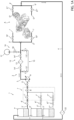
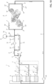
- Reference number 1 generally indicates in the two embodiments of the invention a system for cleaning an e-axle A of a vehicle, such as a truck comprising at least an electric machine.
- the E-axle A of the disclosed embodiments comprises, exemplarily, a pair of machines.
- the cleaning system 1 comprises essentially a plurality of tanks T', T", T′′′ and a hydraulic arrangement 2 fluidly interposed between the plurality of tanks T', T", T′′′ and the e-axle A.
- Each tank T', T", T′′′ is provided with a vent valve (not shown) configured to allow venting of the tank, if needed.
- the hydraulic arrangement 2 comprises a main feeding conduit 3 configured to fluidly connect tanks T', T", T′′′ to the e-axle A, namely, according to the shown embodiment, to a pair of conduits 3', 3" fluidly connectable to inlet openings I', I" realized on the e-axle A, in particular to it electric machines in order to reach the conditioning system thereof, more in particular their cooling jacket.
- the hydraulic arrangement 2 further a main return conduit 4 configured to fluidly connect tanks T', T", T′′′ to the e-axle A, namely, according to the shown embodiment, to a pair of conduits 4', 4" fluidly connectable to outlet openings O', O" realized on the e-axle A, and, similarly to the preceding, in particular to it electric machines in order to reach the conditioning system thereof, more in particular their cooling jacket.
- each tank T', T", T′′′ is fluidly connected to the main feeding conduit 3 via a respective hose 5', 5", 5′′′ that is connectable via respective first valve means 6', 6", 6′′′ to a supply module 7.
- Supply module 7 comprises respective second valve means 7', 7", 7′′′ configured to be respectively fluidly connected to hose 5', 5", 5′′′ each fluidly connected to conduit 3. Downstream to second valve means 7', 7", 7′′′ the supply module 7 further comprises a third valve means 8 interposed between the second valve means 7', 7", 7′′′ and conduit 3.
- Hydraulic arrangement 2 further comprises pump means 9 fluidly interposed on main feeding conduit 3 downstream to supply module 7.
- the hydraulic arrangement 2 may comprise fourth valve means 11 fluidly interposed between the pump means 9 and the supply module 7.
- Hydraulic arrangement 2 then comprises a filtering portion 12 comprising filtering means 13 fluidly interposed between the pumping means 9 and the conduits 4', 4" and configured to filter the fluid pumped by pumping means 9 before injecting into e-axle A via inlet openings I', I".
- Filtering portion 12 further comprises a pair of fifth valves 14', 14" of which one is fluidly interposed on main feeding conduit 3 upstream to filtering means 13 and the other one is fluidly interposed on main feeding conduit 3 downstream to filtering means 13.
- Hydraulic arrangement 2 further comprises a by-pass portion 15 configured to fluidly bypass the filtering portion 12 in order to allow direct fluidic communication from pumping means 9 to inlet openings I', I" without passing from filter means 13, if requested.
- the by-pass portion 15 comprises a by-pass conduit provided with a pair of sixth valves 15', 15" fluidly in series one with respect to the other.
- Hydraulic arrangement 2 further comprises a compressed air source 16 configured to be selectively fluidly connected to main conduit 3 downstream to filtering portion 12 in order to inject compressed air towards e-axle inlet openings I', I".
- the compressed air source 16 advantageously comprise air pumping means 17 fluidly connectable by seventh valve means 18 to the main feeding conduit 3.
- the seventh valve means 18 are fluidly connected downstream to filtering portion 12 but upstream with respect to the fluid connection of the by-pass portion 15 to main feeding conduit 3.
- the hydraulic arrangement 2 further comprises eighth and ninth valve means 19', 19", 21', 21" respectively positioned upstream to inlet openings I', I" and downstream to outlet openings O', O".
- the hydraulic arrangement 2 further comprises filtering means 22 fluidly interposed on main return conduit 4 upstream to the plurality of tanks T', T", T′′′.
- filtering means 22 comprises an inspection portion, e.g. a transparent portion, to understand the quality and the presence of fluid passing therethrough.
- a bypass portion (not shown) may be comprised to exclude the passage of water within filtering means 22, if needed, to reduce required cleaning fluid amount and to reduce time needed for cleaning.
- valves are preferably ON-OFF two ways - two positions valves electrically controlled in order to provide a cleaning method as described in the following.
- FIG 1A a cleaning operation is shown wherein the fluid contained in first tank T', that is heated at a preset temperature, e.g. comprised between 70-90 °C, for instance a liquid compound known with commercial name of "Restore Plus” is make circulate within electric machine cooling system.
- a preset temperature e.g. comprised between 70-90 °C, for instance a liquid compound known with commercial name of "Restore Plus”
- valves 6', 7', 8, 11, 14', 14", 18, 19" are controlled to allow passage of cleaning fluid through pumping means 9 and filtering means 13 and then to the e-axle A.
- the cooling fluid will corrode possible dirty deposition in the cooling jacket of the electric machine/s and the filtering means will collect such debris.
- the cleaning operation is caried out for the time needed in function of the typology and number of electric machines, e.g. 2 hours.
- FIG 1B a further cleaning operation is shown wherein the fluid contained in second tank T", for instance water.
- valves 6', 7', 8, 11, 14', 14", 16', 19" are controlled to allow passage of cleaning fluid through pumping means 9 and bypass portion 15 and then to the e-axle A.
- the water will eliminate further debris contained in the conditioning system and, moreover, eliminate any residual of cleaning fluid.
- the cleaning operation is caried out for the time needed in function of the typology and number of electric machines, e.g. 5 minutes.
- valves 6', 7', 8, 11, 14', 14", 16', 19" are controlled to allow passage of cleaning fluid through pumping means 9 and bypass portion 15 and then to the e-axle A. The operation will be carried out till filling completely the conditioning system for the electric machine of the e-axle A.
- valves 6', 7', 8, 11, 14', 14", 16', 19" are controlled to allow passage of air from compressed air means 16 towards e-axle A and then to one of tanks T', T", T′′′ for discharge. The operation will be carried out till any indication of fluid is completely out of the conditioning system for the electric machine of the e-axle A.
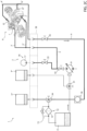
- the first tank T' is directly fluidly connected to main feeding and return conduits 3, 4 while the second tank T", third tank T′′′ and compressed air means 16 are connected to the main feeding and return conduits 3, 4, via a connection panel 30 configured to define a plurality of ports for allowing fluid connections specified in the following.
- the hydraulic arrangement 2 comprises pump means 9 fluidly interposed on main feeding conduit 3 downstream to first tank T'.
- the hydraulic arrangement 2 further comprises first valve means 31 fluidly interposed between the first tank T' and pump means 9 and second valve means 32 fluidly interposed between pump means 9 and the e-axle inlet openings I', I".
- the hydraulic arrangement 2 further comprises third valve means 33 fluidly interposed between compressed air means 16 and the main feeding conduit 3 in a position downstream to second valve means 32.
- third valve means 33 are placed downstream to connection panel 30.
- the hydraulic arrangement 2 according to the second embodiment further comprises fourth valve means 35 fluidly interposed on main return conduit 4 downstream to connection panel 30 and inspection means 36 fluidly interposed on main return conduit 4 downstream to fourth valve means 35.
- inspection means 36 are realized as a transparent portion configured to understand the quality and the presence of fluid passing therethrough.
- the hydraulic arrangement 2 further comprises fifth valve means 34 fluidly interposed on main return conduit 4 downstream to fourth valve means 35 and preferably downstream to inspection means 36 and a filtering portion 15 further interposed on the main return conduit 4 downstream to fifth valve means 34.
- FIG 2A a cleaning operation is shown wherein the fluid contained in first tank T', that is heated at a preset temperature, e.g. comprised between 70-90 °C, for instance a liquid compound known with commercial name of "Restore Plus" is make circulate within electric machine cooling system.
- a preset temperature e.g. comprised between 70-90 °C, for instance a liquid compound known with commercial name of "Restore Plus”
- valves 31, 32, 33, 34, 35 are controlled to allow passage of cleaning fluid through pumping means 9 to the e-axle A AND then through filtering means 13 back to tank T'.
- the cooling fluid will corrode possible dirty deposition in the cooling jacket of the electric machine/s and the filtering means will collect such debris.
- the cleaning operation is caried out for the time needed in function of the typology and number of electric machines, e.g. 2 hours.
- FIG 2B a further cleaning operation is shown wherein the fluid contained in second tank T", for instance water.
- valves 31, 32, 33, 34, 35 are controlled to allow passage of cleaning fluid through pumping means 9 to the e-axle A and then towards third tank T′′′.
- the water will eliminate further debris contained in the conditioning system and, moreover, eliminate any residual of cleaning fluid.
- the cleaning operation is caried out for the time needed in function of the typology and number of electric machines, e.g. 5 minutes.
- valves 31, 32, 33, 34, 35 are controlled to allow passage of air from compressed air means 16 towards e-axle A and then to third tank T′′′ for discharge. The operation will be carried out till any indication of fluid is completely the conditioning system for the electric machine of the e-axle A.
- the filling may be executed by connecting using tanks T", T′′′, properly cleaned and filled with coolant fluid.
- pump means 9 and valve means may be manual activated or may be electrically controlled.
- the cleaning system 1 therefore comprises an electronic control unit (not shown) electrically connected to the pump means 9 and to valve means and comprising elaboration means configured to control their operation.
- the present invention relates to a cleaning method for a e-axle A via a cleaning system as described above comprising the following steps:
- the first cleaning fluid may be the heated corrosive fluid while the second cleaning fluid may be water.
- purge operations are carried out for a preset time, e.g. 5 minutes, or till the filtering means 22 or inspection means 36 does indicate that the conduit is empty.
- the first cleaning operation is advantageously carried out for a pre-set time, e.g. 2 hours.
- the second cleaning operation is advantageously carried out for a pre-set time, e.g. 5 minutes.
- the proposed cleaning system allow to deep and quick clean the conditioning system of an e-axle.
- the system is easy to connect to the e-axle and may be operated by a single user.
- the proposed cleaning system may be actuated manually or automatized by an electronic control unit thereby allowing a further more quick cleaning of the e-axle conditioning system.
- connection panel 30 allows to obtain a cleaning system that is mobile and therefore that can be moved near to the e-axle in the most optimized position for the user.
- the hydraulic topology of the cleaning system may vary without varying its function as demonstrated by the two disclosed embodiments.
- pump means, valve means, inspection means and filtering means may be of any typology.
- the axle may comprise one or more electric machines and thereby the related openings to be fluidly connected to the cleaning system will vary consequently.
Landscapes
- Engineering & Computer Science (AREA)
- Mechanical Engineering (AREA)
- Cleaning In General (AREA)
Applications Claiming Priority (1)
| Application Number | Priority Date | Filing Date | Title |
|---|---|---|---|
| IT102022000027384A IT202200027384A1 (it) | 2022-12-30 | 2022-12-30 | Sistema di pulizia per assale elettrico per veicolo e relativo metodo di pulizia |
Publications (1)
| Publication Number | Publication Date |
|---|---|
| EP4403271A1 true EP4403271A1 (de) | 2024-07-24 |
Family
ID=85556292
Family Applications (1)
| Application Number | Title | Priority Date | Filing Date |
|---|---|---|---|
| EP23220737.3A Pending EP4403271A1 (de) | 2022-12-30 | 2023-12-29 | Reinigungssystem für eine elektrische achse für ein fahrzeug und zugehöriges reinigungsverfahren |
Country Status (2)
| Country | Link |
|---|---|
| EP (1) | EP4403271A1 (de) |
| IT (1) | IT202200027384A1 (de) |
Citations (5)
| Publication number | Priority date | Publication date | Assignee | Title |
|---|---|---|---|---|
| DE4209439A1 (de) * | 1992-03-24 | 1993-09-30 | Kuehl System Recycling | Verfahren und Vorrichtung zur Entleerung und Entsorgung von flüssigen und gasförmigen Medien aus einem Behälter und damit verbundenen Rohrleitungen |
| WO2004112975A1 (en) * | 2003-06-18 | 2004-12-29 | Princeton Trade And Technology, Inc. | Apparatus and method for cleaning pipelines, tubing and membranes using two-phase flow |
| WO2017059119A1 (en) * | 2015-09-29 | 2017-04-06 | Blue Box Air, Llc | Method and system for cleaning heating, ventilation and air conditioning systems |
| WO2020069316A1 (en) * | 2018-09-27 | 2020-04-02 | Allison Transmission, Inc. | Electric motor for an axle assembly |
| US11370001B2 (en) * | 2019-08-26 | 2022-06-28 | Jeffrey J. Seippel | Method and apparatus for cleaning a heat exchanger or water system |
-
2022
- 2022-12-30 IT IT102022000027384A patent/IT202200027384A1/it unknown
-
2023
- 2023-12-29 EP EP23220737.3A patent/EP4403271A1/de active Pending
Patent Citations (5)
| Publication number | Priority date | Publication date | Assignee | Title |
|---|---|---|---|---|
| DE4209439A1 (de) * | 1992-03-24 | 1993-09-30 | Kuehl System Recycling | Verfahren und Vorrichtung zur Entleerung und Entsorgung von flüssigen und gasförmigen Medien aus einem Behälter und damit verbundenen Rohrleitungen |
| WO2004112975A1 (en) * | 2003-06-18 | 2004-12-29 | Princeton Trade And Technology, Inc. | Apparatus and method for cleaning pipelines, tubing and membranes using two-phase flow |
| WO2017059119A1 (en) * | 2015-09-29 | 2017-04-06 | Blue Box Air, Llc | Method and system for cleaning heating, ventilation and air conditioning systems |
| WO2020069316A1 (en) * | 2018-09-27 | 2020-04-02 | Allison Transmission, Inc. | Electric motor for an axle assembly |
| US11370001B2 (en) * | 2019-08-26 | 2022-06-28 | Jeffrey J. Seippel | Method and apparatus for cleaning a heat exchanger or water system |
Also Published As
| Publication number | Publication date |
|---|---|
| IT202200027384A1 (it) | 2024-06-30 |
Similar Documents
| Publication | Publication Date | Title |
|---|---|---|
| AU654894B2 (en) | Engine and radiator coolant treatment and handling, enabling coolant reuse | |
| US6595248B1 (en) | Automated service equipment and method for engine cooling systems | |
| CN103982348A (zh) | 燃料过滤系统 | |
| CN107387598A (zh) | 一种自动变速器高效油源系统 | |
| CN207093614U (zh) | 一种自动变速器高效油源系统 | |
| US20010045222A1 (en) | Method and arrangement for cleaning filters | |
| WO2018017010A1 (en) | Fuel system for an internal combustion engine | |
| CN112576577B (zh) | 用于对车辆液压制动系统处理的设备 | |
| CN113944881B (zh) | 船用管路清洗系统及清洗设备 | |
| CN209838844U (zh) | 闭式液压系统及包括其的工程机械 | |
| US6253805B1 (en) | Apparatus and improved method for changing automatic transmission fluid in motor vehicles | |
| CN202441673U (zh) | 油缸试验台 | |
| EP2955419B1 (de) | Hydraulisches spülsystem | |
| JP2006527680A (ja) | 燃料供給装置 | |
| JP2905193B1 (ja) | エンジンのオイル循環路洗浄方法及び装置 | |
| IT202200027384A1 (it) | Sistema di pulizia per assale elettrico per veicolo e relativo metodo di pulizia | |
| CN113027869B (zh) | 一种吸回油过滤系统、方法及拖拉机 | |
| US20220381198A1 (en) | Methods and systems for controlling engine inlet pressure via a fuel delivery system of a transport climate control system | |
| JPH11148350A (ja) | 車両用エンジンの冷却液交換装置 | |
| CN217926520U (zh) | 一种汽机eh油循环和处理系统 | |
| CN207241546U (zh) | 一种适宜于预约服务的便捷换润滑油维护服务车 | |
| CN222496420U (zh) | 一种拖拉机用转向阀组、系统及拖拉机 | |
| RU2667850C1 (ru) | Устройство для поддержания оптимального уровня чистоты рабочей жидкости в гидравлической системе | |
| KR200357260Y1 (ko) | 차량의 자동 밋션 오일 및 스티어링 오일 겸용 교환장치 | |
| CN217481356U (zh) | 应用于发动机的预供油装置 |
Legal Events
| Date | Code | Title | Description |
|---|---|---|---|
| PUAI | Public reference made under article 153(3) epc to a published international application that has entered the european phase |
Free format text: ORIGINAL CODE: 0009012 |
|
| STAA | Information on the status of an ep patent application or granted ep patent |
Free format text: STATUS: THE APPLICATION HAS BEEN PUBLISHED |
|
| AK | Designated contracting states |
Kind code of ref document: A1 Designated state(s): AL AT BE BG CH CY CZ DE DK EE ES FI FR GB GR HR HU IE IS IT LI LT LU LV MC ME MK MT NL NO PL PT RO RS SE SI SK SM TR |
|
| STAA | Information on the status of an ep patent application or granted ep patent |
Free format text: STATUS: REQUEST FOR EXAMINATION WAS MADE |
|
| 17P | Request for examination filed |
Effective date: 20250122 |