EP4403086B1 - Betriebszyklus einer geschirrspülmaschine - Google Patents
Betriebszyklus einer geschirrspülmaschine Download PDFInfo
- Publication number
- EP4403086B1 EP4403086B1 EP23152112.1A EP23152112A EP4403086B1 EP 4403086 B1 EP4403086 B1 EP 4403086B1 EP 23152112 A EP23152112 A EP 23152112A EP 4403086 B1 EP4403086 B1 EP 4403086B1
- Authority
- EP
- European Patent Office
- Prior art keywords
- water
- outlet
- operating cycle
- wash
- sump
- Prior art date
- Legal status (The legal status is an assumption and is not a legal conclusion. Google has not performed a legal analysis and makes no representation as to the accuracy of the status listed.)
- Active
Links
Images


Classifications
-
- A—HUMAN NECESSITIES
- A47—FURNITURE; DOMESTIC ARTICLES OR APPLIANCES; COFFEE MILLS; SPICE MILLS; SUCTION CLEANERS IN GENERAL
- A47L—DOMESTIC WASHING OR CLEANING; SUCTION CLEANERS IN GENERAL
- A47L15/00—Washing or rinsing machines for crockery or tableware
- A47L15/0018—Controlling processes, i.e. processes to control the operation of the machine characterised by the purpose or target of the control
- A47L15/0021—Regulation of operational steps within the washing processes, e.g. optimisation or improvement of operational steps depending from the detergent nature or from the condition of the crockery
- A47L15/0026—Rinsing phases
-
- A—HUMAN NECESSITIES
- A47—FURNITURE; DOMESTIC ARTICLES OR APPLIANCES; COFFEE MILLS; SPICE MILLS; SUCTION CLEANERS IN GENERAL
- A47L—DOMESTIC WASHING OR CLEANING; SUCTION CLEANERS IN GENERAL
- A47L15/00—Washing or rinsing machines for crockery or tableware
- A47L15/0018—Controlling processes, i.e. processes to control the operation of the machine characterised by the purpose or target of the control
- A47L15/0057—Cleaning of machines parts, e.g. removal of deposits like lime scale or proteins from piping or tub
-
- A—HUMAN NECESSITIES
- A47—FURNITURE; DOMESTIC ARTICLES OR APPLIANCES; COFFEE MILLS; SPICE MILLS; SUCTION CLEANERS IN GENERAL
- A47L—DOMESTIC WASHING OR CLEANING; SUCTION CLEANERS IN GENERAL
- A47L15/00—Washing or rinsing machines for crockery or tableware
- A47L15/42—Details
- A47L15/4214—Water supply, recirculation or discharge arrangements; Devices therefor
- A47L15/4219—Water recirculation
-
- A—HUMAN NECESSITIES
- A47—FURNITURE; DOMESTIC ARTICLES OR APPLIANCES; COFFEE MILLS; SPICE MILLS; SUCTION CLEANERS IN GENERAL
- A47L—DOMESTIC WASHING OR CLEANING; SUCTION CLEANERS IN GENERAL
- A47L2501/00—Output in controlling method of washing or rinsing machines for crockery or tableware, i.e. quantities or components controlled, or actions performed by the controlling device executing the controlling method
- A47L2501/03—Water recirculation, e.g. control of distributing valves for redirection of water flow
-
- A—HUMAN NECESSITIES
- A47—FURNITURE; DOMESTIC ARTICLES OR APPLIANCES; COFFEE MILLS; SPICE MILLS; SUCTION CLEANERS IN GENERAL
- A47L—DOMESTIC WASHING OR CLEANING; SUCTION CLEANERS IN GENERAL
- A47L2501/00—Output in controlling method of washing or rinsing machines for crockery or tableware, i.e. quantities or components controlled, or actions performed by the controlling device executing the controlling method
- A47L2501/04—Water pressure or flow rate
-
- A—HUMAN NECESSITIES
- A47—FURNITURE; DOMESTIC ARTICLES OR APPLIANCES; COFFEE MILLS; SPICE MILLS; SUCTION CLEANERS IN GENERAL
- A47L—DOMESTIC WASHING OR CLEANING; SUCTION CLEANERS IN GENERAL
- A47L2501/00—Output in controlling method of washing or rinsing machines for crockery or tableware, i.e. quantities or components controlled, or actions performed by the controlling device executing the controlling method
- A47L2501/05—Drain or recirculation pump, e.g. regulation of the pump rotational speed or flow direction
Definitions
- the main advantage of the dishwasher according to the present invention is that it is possible to carry out the intermediate rinse by limiting it to the most critical areas of the hydraulic circuit, without affecting the wash tank and the dishes, and without having to make any modification/integration to the hydraulic circuit. This result in a reduction of the dishwasher cost both in terms of components and labor for its assembly, since the hydraulic circuit is simpler and less bulky with respect to the above-cited prior art dishwashers.
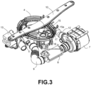
- a dishwasher traditionally comprises a load duct, controlled by a shut-off solenoid valve 1, for loading mains water from a tap to an air break 2, then passing through a softener 3 containing descaling resins, to be finally loaded into a sump 4 at the bottom of the wash tank through a first inlet 5.
- the water is then withdrawn for the wash/rinse phases, through an outlet 6, by a wash pump 7, preceded by a resistor 8 arranged on the suction duct 9.
- the wash pump 7 sends the water to the sprayers 10, 11 through a delivery duct 12, a second inlet 20 and a diverter valve, which controls the inflow to the various sprayers via its three outlets 16, 17, 18 (there is also a third sprayer, not shown, on the ceiling of the wash tank).
- the machine further comprises a drain pump 13, for sending water from sump 4 to a drain duct 14.
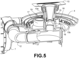
- the lower sprayer 10 is engaged through its stem 10a on a support 15 mounted on the first outlet 16 of the diverter valve, while the upper sprayer 11 and the sprayer on the ceiling of the wash chamber are fed through ducts extending from the second outlet 17 and the third outlet 18 of the diverter valve, respectively.
- Support 15 has an opening 15a in its lower region, flush with the abutment resting on top of the first outlet 16, this opening 15a being usually used for venting air from the hydraulic circuit.
- the novel aspect of this dishwasher is that it is possible to reduce the dynamic water pressure at gap 19, so as to increase the static pressure and make virtually all the water leak into sump 4 through gap 19 and opening 15a.
- the pressure P of the water circulated by the wash pump 7 has a value at least equal to a minimum value P1 such that the water can escape from the spray support 15 through the opening 15a, otherwise the water would not be recirculated, but less than a maximum value P2 that causes water to flow out of the lower sprayer 10, otherwise water would be sprayed on the bottom of the wash tank or even on the dishes resulting in a reduction of their temperature and energy expenditure in bringing them back to temperature for the final rinse.
- outlet 16 of the diverter valve In the intermediate rinse phase, only outlet 16 of the diverter valve is open, while all other outlets 17, 18 are closed.
- the amount of water loaded into sump 4 through inlet 5 is between 25% and 60% of the volume V of the part of the hydraulic circuit to be cleaned, that is, the part between outlet 6 of sump 4 and outlet 16 of the diverter valve.
- the wash pump 7 circulates water only in the lower part of the dishwasher hydraulic circuit, drawing it in from sump 4 through the suction duct 9 and resistor 8, and then sending it back to sump 4 along the delivery duct 12 and through the second inlet 20.
- the water is discharged by the drain pump 13 through the drain duct 14, leaving the wash/rinse circuit clean and ready for the final rinse.
- the duration of the intermediate rinse phase and the amount of water loaded for this phase can be freely chosen depending on the specific circuit cleaning requirements.
- this phase could be divided into multiple sub-phases, that is, it could include multiple sequences of water loading, circuit cleaning, and water draining.
- the amount of water is comprised within the above range of 25-60% of volume V when the wash pump 7 operates at a rotational speed similar to that used in the other phases of the operating cycle, indicatively with a reduction of up to 20%.
- this allows for an increase in the upper limit of the range of the amount of water that is offset by the reduced pump speed (while the lower limit remains unchanged).
- the speed reduction of pump 7 is 40% the upper limit of the loaded water can be 80% of V, if the speed reduction reaches 60% the upper limit can be up to 120% of V (with other intermediate values basically proportional).
- steps e)-h) could also be performed several times, and steps c)-d) could be swapped, as could steps i)-j).
- the dishwasher according to the present invention can perform the final rinse with less energy consumption, since the wash tank and the dishes have not been cooled by the cold water loaded in the previous phase.
- the quantity of water required for washing the wash/rinse circuit which is in any case the part of the hydraulic circuit with the greatest stagnation of polluted water, is significantly less than that required for a traditional intermediate rinse. All of this without having to intervene on the dishwasher structure, but only on the mode of carrying out the intermediate rinse.
- softener 3 and/or air break 2 could be absent, and that in the case of an industrial dishwasher, pump 7 and sprayers 10, 11 would only be intended for washing and there would be a further pump and two further sprayers specifically intended for rinsing, but the part of the circuit illustrated in the figures would not change.
- the embodiment of the dishwasher according to the above-described and illustrated invention is only an example susceptible to numerous variations.
- the diverter valve could have a different number of outlets depending on the number of sprayers, and the exact shape and arrangement of ducts 9, 12, 14 and of inlets 5 and 20, as well as of the possible softener 3 and/or air break 2, may be freely varied according to specific constructional requirements, as long as their relative arrangement within the hydraulic circuit illustrated above is maintained.
Landscapes
- Engineering & Computer Science (AREA)
- Water Supply & Treatment (AREA)
- Washing And Drying Of Tableware (AREA)
Claims (5)
- Betriebszyklus für eine Geschirrspülmaschine, umfassend:- ein Einbringungsventil (1), das den Wasserzufluss von der Hauptleitung durch einen Einbringungskanal steuert, um Wasser durch einen Einlass (5) in eine Bodenwanne (4) einzubringen;- eine Waschpumpe (7), die Wasser aus dem unteren Sumpf (4) durch einen Saugkanal (9) ansaugt und es durch einen Abgabekanal (12) an eine Vielzahl von Sprühvorrichtungen (10, 11) sendet, und ein Ablenkerventil, das den Wasserfluss zu den Sprühvorrichtungen (10, 11) durch eine entsprechende Vielzahl von Auslässen (16, 17, 18) steuert;- eine Ablaufpumpe (13), die an einen Ablaufkanal (14) angeschlossen ist, um Wasser aus der Bodenwanne (4) abzulassen;- eine Halterung (15), die an dem Auslass (16) des Ablenkerventils zu einer unteren Sprühvorrichtung (10) hin angebracht ist, wobei die Halterung (15) in ihrem unteren Bereich eine Öffnung (15a) aufweist und die untere Sprühvorrichtung (10) durch einen Schaft (10a) davon auf der Halterung (15) derart in Eingriff genommen ist, dass zwischen diesen zwei Elementen an der Öffnung (15a) ein kleiner Spalt (19) verbleibt;der Betriebszyklus umfassend die folgenden Schritte:(a) anfängliches Einbringen von Wasser in die Bodenwanne (4);(b) Durchführen der Waschphase;(c) Ablassen des Waschwassers;(d) Schließen aller Auslässe des Ablenkerventils mit Ausnahme des Auslasses (16) zu der unteren Sprühvorrichtung (10) hin;(e) Einbringen von Wasser für die Zwischenspülung in die Bodenwanne (4);(f) Aktivierung der Waschpumpe (7);(g) Deaktivierung der Waschpumpe (7);(h) Ablassen des Zwischenspülwassers;(i) Öffnen aller Auslässe des Ablenkerventils;(j) Einbringen des letzten Spülwassers in die Bodenwanne (4);(k) Durchführen der letzten Spülphase;(l) Ablassen des letzten Spülwassers;dadurch gekennzeichnet, dass die Kombination der in Schritt (e) eingebrachten Wassermenge mit der Rotationsgeschwindigkeit der Waschpumpe (7) in Schritt (f) einen Wasserdruck P erzeugt, der mindestens gleich einem Wert P1 ist, der es ermöglicht, dass Wasser aus der Halterung (15) durch die Öffnung (15a) entweicht, jedoch kleiner als ein Wert P2 ist, der dazu führt, dass Wasser aus der unteren Sprühvorrichtung (10) abgegeben wird;und dadurch, dass die Schritte (c) - (d) sowie die Schritte (i) - (j) ausgetauscht werden könnten.
- Betriebszyklus nach Anspruch 1, dadurch gekennzeichnet, dass die Abfolge der Schritte (e)-(h) mehrmals durchgeführt wird.
- Betriebszyklus nach Anspruch 1 oder 2, dadurch gekennzeichnet, dass in Schritt (e) eine Wassermenge eingebracht wird, die zwischen 25 % und 60 % des Volumens des Abschnitts des Hydraulikkreislaufs beträgt, der zwischen dem Auslass (6) der Wanne (4), an den der Saugkanal (9) angeschlossen ist, und dem Auslass (16) des Ablenkerventils zu der unteren Sprühvorrichtung (10) hin liegt.
- Betriebszyklus nach Anspruch 1 oder 2, dadurch gekennzeichnet, dass in Schritt (e) eine Wassermenge eingebracht wird, die zwischen 25 % und 80 % des Volumens des Abschnitts des Hydraulikkreislaufs beträgt, der zwischen dem Auslass (6) der Wanne (4), an den der Saugkanal (9) angeschlossen ist, und dem Auslass (16) des Ablenkerventils zu der unteren Sprühvorrichtung (10) hin liegt, und in Schritt (f) die Waschpumpe (7) mit einer um etwa 40 % geringeren Rotationsgeschwindigkeit als die in den anderen Schritten des Betriebszyklus verwendete Rotationsgeschwindigkeit in Betrieb ist.
- Betriebszyklus nach Anspruch 1 oder 2, dadurch gekennzeichnet, dass in Schritt (e) eine Wassermenge eingebracht wird, die zwischen 25 % und 120 % des Volumens des Abschnitts des Hydraulikkreislaufs beträgt, der zwischen dem Auslass (6) der Wanne (4), an den der Saugkanal (9) angeschlossen ist, und dem Auslass (16) des Ablenkerventils zu der unteren Sprühvorrichtung (10) hin liegt, und in Schritt (f) die Waschpumpe (7) mit einer um etwa 60 % geringeren Rotationsgeschwindigkeit als die in den anderen Schritten des Betriebszyklus verwendete Rotationsgeschwindigkeit in Betrieb ist.
Priority Applications (1)
| Application Number | Priority Date | Filing Date | Title |
|---|---|---|---|
| EP23152112.1A EP4403086B1 (de) | 2023-01-18 | 2023-01-18 | Betriebszyklus einer geschirrspülmaschine |
Applications Claiming Priority (1)
| Application Number | Priority Date | Filing Date | Title |
|---|---|---|---|
| EP23152112.1A EP4403086B1 (de) | 2023-01-18 | 2023-01-18 | Betriebszyklus einer geschirrspülmaschine |
Publications (3)
| Publication Number | Publication Date |
|---|---|
| EP4403086A1 EP4403086A1 (de) | 2024-07-24 |
| EP4403086B1 true EP4403086B1 (de) | 2025-07-09 |
| EP4403086C0 EP4403086C0 (de) | 2025-07-09 |
Family
ID=85277973
Family Applications (1)
| Application Number | Title | Priority Date | Filing Date |
|---|---|---|---|
| EP23152112.1A Active EP4403086B1 (de) | 2023-01-18 | 2023-01-18 | Betriebszyklus einer geschirrspülmaschine |
Country Status (1)
| Country | Link |
|---|---|
| EP (1) | EP4403086B1 (de) |
Family Cites Families (4)
| Publication number | Priority date | Publication date | Assignee | Title |
|---|---|---|---|---|
| FR2974996B1 (fr) * | 2011-05-09 | 2015-05-01 | Fagorbrandt Sas | Procede de nettoyage de pieces de vaisselle dans une machine a laver la vaisselle. |
| DE102013100859A1 (de) | 2013-01-29 | 2014-07-31 | Miele & Cie. Kg | Geschirrspülautomat sowie Verfahren zur Einleitung von Frischwasser in einen Geschirrspülautomaten |
| KR20150109943A (ko) * | 2014-03-21 | 2015-10-02 | 엘지전자 주식회사 | 식기세척기의 제어방법 |
| DE102017129052A1 (de) | 2017-12-06 | 2019-06-06 | Miele & Cie. Kg | Geschirrspülmaschine |
-
2023
- 2023-01-18 EP EP23152112.1A patent/EP4403086B1/de active Active
Also Published As
| Publication number | Publication date |
|---|---|
| EP4403086C0 (de) | 2025-07-09 |
| EP4403086A1 (de) | 2024-07-24 |
Similar Documents
| Publication | Publication Date | Title |
|---|---|---|
| RU2511466C2 (ru) | Посудомоечная машина с двумя контурами циркуляции | |
| CA1270311A (en) | Low energy, low water consumption warewasher and method | |
| KR100816906B1 (ko) | 식기세척기 및 식기세척기의 제어방법 | |
| EP0405627A1 (de) | Geschirrspülmaschine | |
| CN211066474U (zh) | 洗碗机 | |
| DE102004048091A1 (de) | Geschirrspülmaschine mit thermischer Nachbehandlung | |
| JP2001190479A (ja) | 食器洗浄機 | |
| US9445708B2 (en) | Water-bearing domestic appliance | |
| CN101273871A (zh) | 洗碗机及其控制方法 | |
| CN108951009A (zh) | 一种洗衣机喷淋装置及喷淋方法 | |
| KR20190087150A (ko) | 식기세척기 및 그의 구동방법 | |
| EP3069648B1 (de) | Haushaltswaschmaschine, insbesondere geschirrspüler, mit eine waschmittelabgabevorrichtung sowie verfahren zu seinem betrieb | |
| EP4403086B1 (de) | Betriebszyklus einer geschirrspülmaschine | |
| CA1295212C (en) | Low energy, low water consumption warewasher | |
| KR102577548B1 (ko) | 식기세척기 및 그 제어방법 | |
| EP4374764A1 (de) | Geschirrspülmaschine und entsprechender betriebszyklus | |
| JP2016067646A (ja) | 漬け置きが可能な食器洗浄機 | |
| KR20060124285A (ko) | 식기세척기 및 식기세척기의 제어방법 | |
| EP1868481B1 (de) | Förderbandartiger geschirrspüler mit mehreren behältern und betriebsverfahren dafür | |
| JP4018062B2 (ja) | 食器洗浄機と排水冷却ユニット | |
| JP2000014621A (ja) | 排水冷却器及び排水冷却器を備えた食器洗浄機 | |
| KR20100128862A (ko) | 폐열회수장치가 구비된 업소용 식기세척기 | |
| JP2002291681A (ja) | 食器洗い乾燥機用給湯ユニット及びそれを用いた食器洗い乾燥システム | |
| JP3340334B2 (ja) | 飯米処理機能を備えた食器洗浄機 | |
| EP2164379B1 (de) | Geschirrspülmaschine |
Legal Events
| Date | Code | Title | Description |
|---|---|---|---|
| PUAI | Public reference made under article 153(3) epc to a published international application that has entered the european phase |
Free format text: ORIGINAL CODE: 0009012 |
|
| STAA | Information on the status of an ep patent application or granted ep patent |
Free format text: STATUS: THE APPLICATION HAS BEEN PUBLISHED |
|
| AK | Designated contracting states |
Kind code of ref document: A1 Designated state(s): AL AT BE BG CH CY CZ DE DK EE ES FI FR GB GR HR HU IE IS IT LI LT LU LV MC ME MK MT NL NO PL PT RO RS SE SI SK SM TR |
|
| STAA | Information on the status of an ep patent application or granted ep patent |
Free format text: STATUS: REQUEST FOR EXAMINATION WAS MADE |
|
| 17P | Request for examination filed |
Effective date: 20241023 |
|
| RBV | Designated contracting states (corrected) |
Designated state(s): AL AT BE BG CH CY CZ DE DK EE ES FI FR GB GR HR HU IE IS IT LI LT LU LV MC ME MK MT NL NO PL PT RO RS SE SI SK SM TR |
|
| GRAP | Despatch of communication of intention to grant a patent |
Free format text: ORIGINAL CODE: EPIDOSNIGR1 |
|
| STAA | Information on the status of an ep patent application or granted ep patent |
Free format text: STATUS: GRANT OF PATENT IS INTENDED |
|
| RIC1 | Information provided on ipc code assigned before grant |
Ipc: A47L 15/42 20060101ALI20250129BHEP Ipc: A47L 15/00 20060101AFI20250129BHEP |
|
| INTG | Intention to grant announced |
Effective date: 20250211 |
|
| GRAS | Grant fee paid |
Free format text: ORIGINAL CODE: EPIDOSNIGR3 |
|
| GRAA | (expected) grant |
Free format text: ORIGINAL CODE: 0009210 |
|
| STAA | Information on the status of an ep patent application or granted ep patent |
Free format text: STATUS: THE PATENT HAS BEEN GRANTED |
|
| AK | Designated contracting states |
Kind code of ref document: B1 Designated state(s): AL AT BE BG CH CY CZ DE DK EE ES FI FR GB GR HR HU IE IS IT LI LT LU LV MC ME MK MT NL NO PL PT RO RS SE SI SK SM TR |
|
| REG | Reference to a national code |
Ref country code: GB Ref legal event code: FG4D |
|
| REG | Reference to a national code |
Ref country code: CH Ref legal event code: EP |
|
| REG | Reference to a national code |
Ref country code: IE Ref legal event code: FG4D |
|
| REG | Reference to a national code |
Ref country code: DE Ref legal event code: R096 Ref document number: 602023004578 Country of ref document: DE |
|
| U01 | Request for unitary effect filed |
Effective date: 20250723 |
|
| U07 | Unitary effect registered |
Designated state(s): AT BE BG DE DK EE FI FR IT LT LU LV MT NL PT RO SE SI Effective date: 20250729 |
|
| PG25 | Lapsed in a contracting state [announced via postgrant information from national office to epo] |
Ref country code: IS Free format text: LAPSE BECAUSE OF FAILURE TO SUBMIT A TRANSLATION OF THE DESCRIPTION OR TO PAY THE FEE WITHIN THE PRESCRIBED TIME-LIMIT Effective date: 20251109 |
|
| PG25 | Lapsed in a contracting state [announced via postgrant information from national office to epo] |
Ref country code: NO Free format text: LAPSE BECAUSE OF FAILURE TO SUBMIT A TRANSLATION OF THE DESCRIPTION OR TO PAY THE FEE WITHIN THE PRESCRIBED TIME-LIMIT Effective date: 20251009 |
|
| PG25 | Lapsed in a contracting state [announced via postgrant information from national office to epo] |
Ref country code: HR Free format text: LAPSE BECAUSE OF FAILURE TO SUBMIT A TRANSLATION OF THE DESCRIPTION OR TO PAY THE FEE WITHIN THE PRESCRIBED TIME-LIMIT Effective date: 20250709 |
|
| PG25 | Lapsed in a contracting state [announced via postgrant information from national office to epo] |
Ref country code: GR Free format text: LAPSE BECAUSE OF FAILURE TO SUBMIT A TRANSLATION OF THE DESCRIPTION OR TO PAY THE FEE WITHIN THE PRESCRIBED TIME-LIMIT Effective date: 20251010 |
|
| PG25 | Lapsed in a contracting state [announced via postgrant information from national office to epo] |
Ref country code: PL Free format text: LAPSE BECAUSE OF FAILURE TO SUBMIT A TRANSLATION OF THE DESCRIPTION OR TO PAY THE FEE WITHIN THE PRESCRIBED TIME-LIMIT Effective date: 20250709 |
|
| PG25 | Lapsed in a contracting state [announced via postgrant information from national office to epo] |
Ref country code: RS Free format text: LAPSE BECAUSE OF FAILURE TO SUBMIT A TRANSLATION OF THE DESCRIPTION OR TO PAY THE FEE WITHIN THE PRESCRIBED TIME-LIMIT Effective date: 20251009 |
|
| PG25 | Lapsed in a contracting state [announced via postgrant information from national office to epo] |
Ref country code: ES Free format text: LAPSE BECAUSE OF FAILURE TO SUBMIT A TRANSLATION OF THE DESCRIPTION OR TO PAY THE FEE WITHIN THE PRESCRIBED TIME-LIMIT Effective date: 20250709 |
|
| U20 | Renewal fee for the european patent with unitary effect paid |
Year of fee payment: 4 Effective date: 20260122 |
|
| PG25 | Lapsed in a contracting state [announced via postgrant information from national office to epo] |
Ref country code: SM Free format text: LAPSE BECAUSE OF FAILURE TO SUBMIT A TRANSLATION OF THE DESCRIPTION OR TO PAY THE FEE WITHIN THE PRESCRIBED TIME-LIMIT Effective date: 20250709 |