EP4402091B1 - A pumping system with an equalizer tube - Google Patents
A pumping system with an equalizer tube Download PDFInfo
- Publication number
- EP4402091B1 EP4402091B1 EP22764421.8A EP22764421A EP4402091B1 EP 4402091 B1 EP4402091 B1 EP 4402091B1 EP 22764421 A EP22764421 A EP 22764421A EP 4402091 B1 EP4402091 B1 EP 4402091B1
- Authority
- EP
- European Patent Office
- Prior art keywords
- fuel
- additive
- pumping
- pumping unit
- recovery chamber
- Prior art date
- Legal status (The legal status is an assumption and is not a legal conclusion. Google has not performed a legal analysis and makes no representation as to the accuracy of the status listed.)
- Active
Links
Images

Classifications
-
- B—PERFORMING OPERATIONS; TRANSPORTING
- B67—OPENING, CLOSING OR CLEANING BOTTLES, JARS OR SIMILAR CONTAINERS; LIQUID HANDLING
- B67D—DISPENSING, DELIVERING OR TRANSFERRING LIQUIDS, NOT OTHERWISE PROVIDED FOR
- B67D7/00—Apparatus or devices for transferring liquids from bulk storage containers or reservoirs into vehicles or into portable containers, e.g. for retail sale purposes
- B67D7/04—Apparatus or devices for transferring liquids from bulk storage containers or reservoirs into vehicles or into portable containers, e.g. for retail sale purposes for transferring fuels, lubricants or mixed fuels and lubricants
- B67D7/0476—Vapour recovery systems
- B67D7/0478—Vapour recovery systems constructional features or components
-
- B—PERFORMING OPERATIONS; TRANSPORTING
- B67—OPENING, CLOSING OR CLEANING BOTTLES, JARS OR SIMILAR CONTAINERS; LIQUID HANDLING
- B67D—DISPENSING, DELIVERING OR TRANSFERRING LIQUIDS, NOT OTHERWISE PROVIDED FOR
- B67D7/00—Apparatus or devices for transferring liquids from bulk storage containers or reservoirs into vehicles or into portable containers, e.g. for retail sale purposes
- B67D7/06—Details or accessories
- B67D7/58—Arrangements of pumps
- B67D7/62—Arrangements of pumps power operated
- B67D7/66—Arrangements of pumps power operated of rotary type
-
- B—PERFORMING OPERATIONS; TRANSPORTING
- B67—OPENING, CLOSING OR CLEANING BOTTLES, JARS OR SIMILAR CONTAINERS; LIQUID HANDLING
- B67D—DISPENSING, DELIVERING OR TRANSFERRING LIQUIDS, NOT OTHERWISE PROVIDED FOR
- B67D7/00—Apparatus or devices for transferring liquids from bulk storage containers or reservoirs into vehicles or into portable containers, e.g. for retail sale purposes
- B67D7/06—Details or accessories
- B67D7/58—Arrangements of pumps
- B67D7/70—Arrangements of pumps of two or more pumps in series or parallel
-
- B—PERFORMING OPERATIONS; TRANSPORTING
- B67—OPENING, CLOSING OR CLEANING BOTTLES, JARS OR SIMILAR CONTAINERS; LIQUID HANDLING
- B67D—DISPENSING, DELIVERING OR TRANSFERRING LIQUIDS, NOT OTHERWISE PROVIDED FOR
- B67D7/00—Apparatus or devices for transferring liquids from bulk storage containers or reservoirs into vehicles or into portable containers, e.g. for retail sale purposes
- B67D7/06—Details or accessories
- B67D7/76—Arrangements of devices for purifying liquids to be transferred, e.g. of filters, of air or water separators
- B67D7/763—Arrangements of devices for purifying liquids to be transferred, e.g. of filters, of air or water separators of air separators
-
- B—PERFORMING OPERATIONS; TRANSPORTING
- B67—OPENING, CLOSING OR CLEANING BOTTLES, JARS OR SIMILAR CONTAINERS; LIQUID HANDLING
- B67D—DISPENSING, DELIVERING OR TRANSFERRING LIQUIDS, NOT OTHERWISE PROVIDED FOR
- B67D7/00—Apparatus or devices for transferring liquids from bulk storage containers or reservoirs into vehicles or into portable containers, e.g. for retail sale purposes
- B67D7/06—Details or accessories
- B67D7/78—Arrangements of storage tanks, reservoirs or pipe-lines
-
- B—PERFORMING OPERATIONS; TRANSPORTING
- B67—OPENING, CLOSING OR CLEANING BOTTLES, JARS OR SIMILAR CONTAINERS; LIQUID HANDLING
- B67D—DISPENSING, DELIVERING OR TRANSFERRING LIQUIDS, NOT OTHERWISE PROVIDED FOR
- B67D7/00—Apparatus or devices for transferring liquids from bulk storage containers or reservoirs into vehicles or into portable containers, e.g. for retail sale purposes
- B67D7/06—Details or accessories
- B67D7/74—Devices for mixing two or more different liquids to be transferred
- B67D2007/745—Devices for mixing two or more different liquids to be transferred for obtaining fuel of a given octane level
- B67D2007/748—Devices for mixing two or more different liquids to be transferred for obtaining fuel of a given octane level by mixing fuel with additives, e.g. anti-knocking agents
-
- B—PERFORMING OPERATIONS; TRANSPORTING
- B67—OPENING, CLOSING OR CLEANING BOTTLES, JARS OR SIMILAR CONTAINERS; LIQUID HANDLING
- B67D—DISPENSING, DELIVERING OR TRANSFERRING LIQUIDS, NOT OTHERWISE PROVIDED FOR
- B67D2210/00—Indexing scheme relating to aspects and details of apparatus or devices for dispensing beverages on draught or for controlling flow of liquids under gravity from storage containers for dispensing purposes
- B67D2210/00002—Purifying means
- B67D2210/00005—Filters
- B67D2210/0001—Filters for liquid
-
- B—PERFORMING OPERATIONS; TRANSPORTING
- B67—OPENING, CLOSING OR CLEANING BOTTLES, JARS OR SIMILAR CONTAINERS; LIQUID HANDLING
- B67D—DISPENSING, DELIVERING OR TRANSFERRING LIQUIDS, NOT OTHERWISE PROVIDED FOR
- B67D2210/00—Indexing scheme relating to aspects and details of apparatus or devices for dispensing beverages on draught or for controlling flow of liquids under gravity from storage containers for dispensing purposes
- B67D2210/00028—Constructional details
- B67D2210/00047—Piping
- B67D2210/0006—Manifolds
Definitions
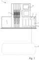
- the invention relates to a pumping system for a fuel dispensing unit.
- the invention also relates to a fuel dispensing unit for refueling vehicles.
- Fuel dispensing unit classically comprises one or more pumping units comprising each a pump sucking fuel from an underground fuel tank toward a supply line connected to one or two fuel nozzles intended to deliver fuel to a vehicle.
- an additive is added to the fuel of a pumping unit for various reasons.
- the additive constitutes a highly inflammable substance and is normally held in a container which is placed in connection to the fuel dispensing unit and is connected thereto.
- the additive is classically pumped into the fuel at a pressure side of a fuel pumping unit inside the fuel dispensing unit.
- the additive itself is pumped by means of a pump driven by a motor.
- Each filter device comprises a filter and a valve allowing fuel to circulate from the fuel tank toward the pumping unit and blocking the fuel flow when the fuel circulates in opposite direction.
- a fall back pressure appears when one of a first pumping unit is stopped after a fuel delivery because the stop is brutal.
- the issue is more the fuel velocity than the pressure because the fuel flow takes time to stop and comes back through the valve of the filter device of the passive second pumping unit that is not used.
- Each pumping unit comprises a degassing device to ensure that the measurement of the volume of fuel delivered to the user in fact corresponds to liquid fuel and not to a mixture of liquid fuel and gas (air and petroleum vapors).
- the first cover may have transversal section with a "L" shape and comprises a first horizontal part supporting a first motor and a first vertical part protruding upwardly from the first horizontal part, the first hole being located at a first bottom position of the first vertical part of the first cover, the second cover having a transversal section with a "L" shape and comprises a second horizontal part supporting a second motor and a second vertical part protruding upwardly from the second horizontal part, the second hole being located at a second bottom position of the second vertical part of the second cover.
- the first additive inlet may be arranged at a bottom section of the first filter device or the second filter device.
- the first filter device or the second filter device may be connected to the additive dispensing unit via an injection coupling comprising the first additive inlet.
- the injection coupling may comprise a drainage bore intended to drain fuel from the first filter device toward the first pumping unit or from the second filter device toward the second pumping unit.
- the drainage bore may comprise an internal thread for screwing a pressure sensor.
- the first additive inlet may be connected to a first additive line of the additive dispensing unit, the injection coupling comprising a second additive inlet connected to a second additive line of the additive dispensing unit.
- the second pumping unit 4 comprises a second air separator (not shown) for circulating a part of the fuel with low rate of gas toward the second fuel supply line 16.
- the second air separator is further configured to evacuate a gas-enriched part of the fuel toward the second recovery chamber 19.
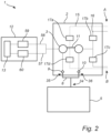
- the pumping system 2 comprises the first filter device 9 and the second filter device 10.
- the first and second filter device 9,10 are provided downstream of the first and second fuel outlet 35, 36 of the manifold 8 and upstream of the first and second supply inlet 37, 38 of the first and second pumping units 3,4.
- the first pumping unit 3 comprises a first recovery chamber 18.
- the first recovery chamber 18 comprises a first gas outlet 20.
- the second pumping unit 4 comprises a second recovery chamber 19.
- the second recovery chamber 19 comprises a second gas outlet 21.
- the equalizer tube 11 is arranged to fluidly connect the first and second recovery chamber 18,19.
- the equalizer tube 11 comprises a first end 39 connecting a first hole 24 of the first recovery chamber 18 and a second end 40 connecting a second hole 25 of the second recovery chamber 19.
- the first hole 24 is located between the first gas outlet 20 and a first fuel outlet 22 of the first recovery chamber 18.
- the second hole 25 is located between the second gas outlet 21 and a second fuel outlet 23 of the second recovery chamber 19.
- the first and second recovery chamber 18,19 are further described in connection with Fig. 4 .
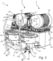
- the equalizer tube 11 has a "U" shape.
- the equalizer tube 11 may be a fuel line of any suitable dimension, allowing gas and/or fuel to flow from one recovery chamber to another one.
- the equalizer tube 11 could be made of steel or polymer.
- the equalizer tube 11 could be formed of a single part.
- the equalizer tube 11 comprises a first part 62 connected to a second part 63 via a coupling 64 as illustrated in Fig.3 .
- the coupling 64 enables the first part 62 to rotates with respect to the second part 63.
- the distance between the two pumping units 3, 4 could vary a little from one pumping system 2 to another.
- the coupling 64 enables thus to adjust the length of the equalizer tube 11 during the mounting.
- first part 62 can be fixed to the first pumping unit 3 via the first end 39 and the second part 63 can be fixed to the second pumping unit 4 via the second end 40.
- the two parts 62, 63 are then connected by means of the coupling 64.
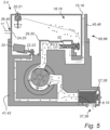
- Each pumping unit 3, 4 comprises a degassing device 65, 66 in order to ensure that the measurement of the volume of fuel delivered to the user in fact corresponds to liquid fuel and not to a mixture of liquid fuel and gas (air and petroleum vapors).
- the first pumping unit 3 comprises a first degassing device 65 comprising a first air separator 29 and the first recovery chamber 18.
- the second pumping unit 4 comprises a second degassing device 66 comprising a second air separator 30 and the second recovery chamber 19.
- the recovery chamber 18,19 comprises a gas outlet 20, 21 connected to atmosphere to evacuate the gas and a fuel outlet 22, 23 equipped with a valve 33 configured to recirculate the degassed part of the fuel toward the pump.
- the recovery chamber 18,19 can be emptied of fuel when the pumping unit is running.
- a gas enriched mixture of fuel and air enters from the bottom right of Fig. 5 , where it passes through the filter device 9,10. After the filter device 9,10, it is sucked into to the air separator 29,30. In the air separator 29,30, the mixture of fuel and air is circulated to separate the air from the liquid fuel.
- the degassed fuel is outputted through the lateral output pipe 31 to the fuel supply line 15,16.
- the air, together with a small amount of fuel is outputted through the axial pipe 32 into the recovery chamber 18,19.
- the recovery chamber 18,19 comprises a gas outlet 20,21 through which the air can be evacuated.
- the first pumping unit 3 comprises a first pump body 41 and a first cover 45 mounted above the first pump body 41 for closing the first recovery chamber 18.
- the first hole 24 receiving the first end 39 of the equalizer tube 11 is located on the first cover 45.
- the second pumping unit 4 comprises a second pump body 42 and a second cover 46 mounted above the second pump body 42 for closing the second recovery chamber 19.
- the second hole 25 receiving the second end 40 of the equalizer tube 11 is located on the second cover 46.
Landscapes
- Engineering & Computer Science (AREA)
- Mechanical Engineering (AREA)
- Cooling, Air Intake And Gas Exhaust, And Fuel Tank Arrangements In Propulsion Units (AREA)
- Loading And Unloading Of Fuel Tanks Or Ships (AREA)
- Jet Pumps And Other Pumps (AREA)
- Amplifiers (AREA)
Applications Claiming Priority (2)
| Application Number | Priority Date | Filing Date | Title |
|---|---|---|---|
| SE2151136A SE545426C2 (en) | 2021-09-16 | 2021-09-16 | A pumping system with an equalizer tube |
| PCT/EP2022/072578 WO2023041265A1 (en) | 2021-09-16 | 2022-08-11 | A pumping system with an equalizer tube |
Publications (3)
| Publication Number | Publication Date |
|---|---|
| EP4402091A1 EP4402091A1 (en) | 2024-07-24 |
| EP4402091C0 EP4402091C0 (en) | 2025-07-02 |
| EP4402091B1 true EP4402091B1 (en) | 2025-07-02 |
Family
ID=83188557
Family Applications (1)
| Application Number | Title | Priority Date | Filing Date |
|---|---|---|---|
| EP22764421.8A Active EP4402091B1 (en) | 2021-09-16 | 2022-08-11 | A pumping system with an equalizer tube |
Country Status (9)
| Country | Link |
|---|---|
| US (1) | US20250136431A1 (es) |
| EP (1) | EP4402091B1 (es) |
| CN (1) | CN117916189A (es) |
| AU (1) | AU2022347955A1 (es) |
| CA (1) | CA3229504A1 (es) |
| ES (1) | ES3047701T3 (es) |
| MX (1) | MX2024003000A (es) |
| SE (1) | SE545426C2 (es) |
| WO (1) | WO2023041265A1 (es) |
Family Cites Families (10)
| Publication number | Priority date | Publication date | Assignee | Title |
|---|---|---|---|---|
| US3052378A (en) * | 1956-06-13 | 1962-09-04 | Tokheim Corp | Booster pumping system |
| NL8204774A (nl) * | 1982-12-09 | 1984-07-02 | Stork Pompen | Verpompingsinrichting. |
| FR2636056B1 (fr) | 1988-09-02 | 1991-05-24 | Schlumberger Ind Sa | Dispositif de commande automatique d'une lance a hydrocarbure en fonction de la teneur en gaz de l'hydrocarbure |
| GB9501904D0 (en) * | 1995-01-31 | 1995-03-22 | Osborne Graham W | Forecourt fuel pumps |
| US5884809A (en) * | 1997-05-05 | 1999-03-23 | Delaware Capital Formation, Inc. | Air separating fuel dispensing system |
| AU2002234842A1 (en) * | 2001-02-27 | 2002-09-12 | Kevin Dowling | Method and apparatus for adding an additive to a fluid |
| EP1936189B1 (en) * | 2006-12-19 | 2011-02-23 | Dresser Wayne Aktiebolag | Fluid pump and fuel dispenser |
| US20180237289A1 (en) * | 2015-09-03 | 2018-08-23 | Additech, Inc. | Time pressure dosing fuel additive delivery system |
| ES2704753T3 (es) * | 2016-05-31 | 2019-03-19 | Sfc Energy Ag | Dispositivo para la extracción de combustible de cartuchos de combustible para pilas de combustible |
| SE543664C2 (en) * | 2019-06-05 | 2021-05-25 | Wayne Fueling Systems Sweden Ab | A fuel dispensing unit and a method for handling additives inside a fuel dispensing unit |
-
2021
- 2021-09-16 SE SE2151136A patent/SE545426C2/en unknown
-
2022
- 2022-08-11 ES ES22764421T patent/ES3047701T3/es active Active
- 2022-08-11 EP EP22764421.8A patent/EP4402091B1/en active Active
- 2022-08-11 MX MX2024003000A patent/MX2024003000A/es unknown
- 2022-08-11 CN CN202280061349.9A patent/CN117916189A/zh active Pending
- 2022-08-11 AU AU2022347955A patent/AU2022347955A1/en active Pending
- 2022-08-11 US US18/684,027 patent/US20250136431A1/en active Pending
- 2022-08-11 CA CA3229504A patent/CA3229504A1/en active Pending
- 2022-08-11 WO PCT/EP2022/072578 patent/WO2023041265A1/en not_active Ceased
Also Published As
| Publication number | Publication date |
|---|---|
| ES3047701T3 (en) | 2025-12-04 |
| EP4402091A1 (en) | 2024-07-24 |
| CA3229504A1 (en) | 2023-03-23 |
| CN117916189A (zh) | 2024-04-19 |
| AU2022347955A1 (en) | 2024-02-29 |
| WO2023041265A1 (en) | 2023-03-23 |
| US20250136431A1 (en) | 2025-05-01 |
| SE2151136A1 (en) | 2023-03-17 |
| EP4402091C0 (en) | 2025-07-02 |
| MX2024003000A (es) | 2024-03-27 |
| SE545426C2 (en) | 2023-09-05 |
Similar Documents
| Publication | Publication Date | Title |
|---|---|---|
| US7303378B2 (en) | Apparatus for delivering fuel from a tank to an internal combustion engine | |
| US6607005B2 (en) | Fuel tank | |
| US4310033A (en) | Liquid dispensing and uphill vapor recovery system | |
| US3807433A (en) | Service station vapor collection system | |
| US3826291A (en) | Dispensing volatile hydrocarbon fuels | |
| US9580296B2 (en) | Vertical storage unit for dispensing a fuel additive | |
| US10495039B2 (en) | Fuel system having a jet pump | |
| EP4402091B1 (en) | A pumping system with an equalizer tube | |
| JP2000043589A (ja) | 燃料タンク | |
| US6460562B1 (en) | Dual tank simultaneous fill system | |
| US5613535A (en) | Fuel dispenser shutoff switch | |
| US9394866B2 (en) | Fuel supply system and method | |
| EP3747829B1 (en) | Additive explosion risk | |
| BR102013027740A2 (pt) | Sistema de tanque para um veículo motorizado | |
| CN220017015U (zh) | 一种双向副泵管路及供油系统 | |
| US3057518A (en) | Liquid dispensing apparatus | |
| CN211574772U (zh) | 一种汽车总装车间集中供液系统 | |
| US8113238B2 (en) | Pumping system with manifold vent | |
| WO2021233257A1 (zh) | 用于从容器内分配液体的装置及其抽提管 | |
| CN110864222A (zh) | 汽车总装车间集中供液系统 | |
| US20250135874A1 (en) | Operating Medium Vessel for a Vehicle and Vehicle Having an Operating Medium Vessel | |
| IL129099A (en) | Aircraft fuel transfer pump with auxiliary fuel line scavenge pump | |
| WO2012138623A1 (en) | Fueling nozzle having boot relief valve for orvr | |
| CN215408884U (zh) | 油泵液位检测装置 | |
| KR100314459B1 (ko) | 잔류연료의사용량을증가하는연료탱크 |
Legal Events
| Date | Code | Title | Description |
|---|---|---|---|
| STAA | Information on the status of an ep patent application or granted ep patent |
Free format text: STATUS: UNKNOWN |
|
| STAA | Information on the status of an ep patent application or granted ep patent |
Free format text: STATUS: THE INTERNATIONAL PUBLICATION HAS BEEN MADE |
|
| PUAI | Public reference made under article 153(3) epc to a published international application that has entered the european phase |
Free format text: ORIGINAL CODE: 0009012 |
|
| STAA | Information on the status of an ep patent application or granted ep patent |
Free format text: STATUS: REQUEST FOR EXAMINATION WAS MADE |
|
| 17P | Request for examination filed |
Effective date: 20240328 |
|
| AK | Designated contracting states |
Kind code of ref document: A1 Designated state(s): AL AT BE BG CH CY CZ DE DK EE ES FI FR GB GR HR HU IE IS IT LI LT LU LV MC MK MT NL NO PL PT RO RS SE SI SK SM TR |
|
| DAV | Request for validation of the european patent (deleted) | ||
| DAX | Request for extension of the european patent (deleted) | ||
| GRAP | Despatch of communication of intention to grant a patent |
Free format text: ORIGINAL CODE: EPIDOSNIGR1 |
|
| STAA | Information on the status of an ep patent application or granted ep patent |
Free format text: STATUS: GRANT OF PATENT IS INTENDED |
|
| INTG | Intention to grant announced |
Effective date: 20250317 |
|
| GRAS | Grant fee paid |
Free format text: ORIGINAL CODE: EPIDOSNIGR3 |
|
| GRAA | (expected) grant |
Free format text: ORIGINAL CODE: 0009210 |
|
| STAA | Information on the status of an ep patent application or granted ep patent |
Free format text: STATUS: THE PATENT HAS BEEN GRANTED |
|
| AK | Designated contracting states |
Kind code of ref document: B1 Designated state(s): AL AT BE BG CH CY CZ DE DK EE ES FI FR GB GR HR HU IE IS IT LI LT LU LV MC MK MT NL NO PL PT RO RS SE SI SK SM TR |
|
| REG | Reference to a national code |
Ref country code: GB Ref legal event code: FG4D |
|
| REG | Reference to a national code |
Ref country code: CH Ref legal event code: EP |
|
| REG | Reference to a national code |
Ref country code: DE Ref legal event code: R096 Ref document number: 602022017013 Country of ref document: DE |
|
| REG | Reference to a national code |
Ref country code: IE Ref legal event code: FG4D |
|
| U01 | Request for unitary effect filed |
Effective date: 20250703 |
|
| U07 | Unitary effect registered |
Designated state(s): AT BE BG DE DK EE FI FR IT LT LU LV MT NL PT RO SE SI Effective date: 20250710 |
|
| U20 | Renewal fee for the european patent with unitary effect paid |
Year of fee payment: 4 Effective date: 20250825 |
|
| PGFP | Annual fee paid to national office [announced via postgrant information from national office to epo] |
Ref country code: ES Payment date: 20250916 Year of fee payment: 4 |
|
| PGFP | Annual fee paid to national office [announced via postgrant information from national office to epo] |
Ref country code: CZ Payment date: 20250807 Year of fee payment: 4 |
|
| REG | Reference to a national code |
Ref country code: ES Ref legal event code: FG2A Ref document number: 3047701 Country of ref document: ES Kind code of ref document: T3 Effective date: 20251204 |
|
| PG25 | Lapsed in a contracting state [announced via postgrant information from national office to epo] |
Ref country code: IS Free format text: LAPSE BECAUSE OF FAILURE TO SUBMIT A TRANSLATION OF THE DESCRIPTION OR TO PAY THE FEE WITHIN THE PRESCRIBED TIME-LIMIT Effective date: 20251102 |
|
| PG25 | Lapsed in a contracting state [announced via postgrant information from national office to epo] |
Ref country code: NO Free format text: LAPSE BECAUSE OF FAILURE TO SUBMIT A TRANSLATION OF THE DESCRIPTION OR TO PAY THE FEE WITHIN THE PRESCRIBED TIME-LIMIT Effective date: 20251002 |
|
| PG25 | Lapsed in a contracting state [announced via postgrant information from national office to epo] |
Ref country code: HR Free format text: LAPSE BECAUSE OF FAILURE TO SUBMIT A TRANSLATION OF THE DESCRIPTION OR TO PAY THE FEE WITHIN THE PRESCRIBED TIME-LIMIT Effective date: 20250702 |
|
| PG25 | Lapsed in a contracting state [announced via postgrant information from national office to epo] |
Ref country code: GR Free format text: LAPSE BECAUSE OF FAILURE TO SUBMIT A TRANSLATION OF THE DESCRIPTION OR TO PAY THE FEE WITHIN THE PRESCRIBED TIME-LIMIT Effective date: 20251003 |
|
| PG25 | Lapsed in a contracting state [announced via postgrant information from national office to epo] |
Ref country code: PL Free format text: LAPSE BECAUSE OF FAILURE TO SUBMIT A TRANSLATION OF THE DESCRIPTION OR TO PAY THE FEE WITHIN THE PRESCRIBED TIME-LIMIT Effective date: 20250702 |
|
| PG25 | Lapsed in a contracting state [announced via postgrant information from national office to epo] |
Ref country code: RS Free format text: LAPSE BECAUSE OF FAILURE TO SUBMIT A TRANSLATION OF THE DESCRIPTION OR TO PAY THE FEE WITHIN THE PRESCRIBED TIME-LIMIT Effective date: 20251002 |
|
| REG | Reference to a national code |
Ref country code: CH Ref legal event code: H13 Free format text: ST27 STATUS EVENT CODE: U-0-0-H10-H13 (AS PROVIDED BY THE NATIONAL OFFICE) Effective date: 20260324 |