EP4400845A1 - Einweg-trennchip - Google Patents
Einweg-trennchip Download PDFInfo
- Publication number
- EP4400845A1 EP4400845A1 EP22883907.2A EP22883907A EP4400845A1 EP 4400845 A1 EP4400845 A1 EP 4400845A1 EP 22883907 A EP22883907 A EP 22883907A EP 4400845 A1 EP4400845 A1 EP 4400845A1
- Authority
- EP
- European Patent Office
- Prior art keywords
- channel
- upper plate
- chip
- separation chip
- disposable
- Prior art date
- Legal status (The legal status is an assumption and is not a legal conclusion. Google has not performed a legal analysis and makes no representation as to the accuracy of the status listed.)
- Pending
Links
Images



Classifications
-
- B—PERFORMING OPERATIONS; TRANSPORTING
- B01—PHYSICAL OR CHEMICAL PROCESSES OR APPARATUS IN GENERAL
- B01L—CHEMICAL OR PHYSICAL LABORATORY APPARATUS FOR GENERAL USE
- B01L3/00—Containers or dishes for laboratory use, e.g. laboratory glassware; Droppers
- B01L3/50—Containers for the purpose of retaining a material to be analysed, e.g. test tubes
- B01L3/502—Containers for the purpose of retaining a material to be analysed, e.g. test tubes with fluid transport, e.g. in multi-compartment structures
- B01L3/5027—Containers for the purpose of retaining a material to be analysed, e.g. test tubes with fluid transport, e.g. in multi-compartment structures by integrated microfluidic structures, i.e. dimensions of channels and chambers are such that surface tension forces are important, e.g. lab-on-a-chip
- B01L3/502761—Containers for the purpose of retaining a material to be analysed, e.g. test tubes with fluid transport, e.g. in multi-compartment structures by integrated microfluidic structures, i.e. dimensions of channels and chambers are such that surface tension forces are important, e.g. lab-on-a-chip specially adapted for handling suspended solids or molecules independently from the bulk fluid flow, e.g. for trapping or sorting beads or physically stretching molecules
-
- B—PERFORMING OPERATIONS; TRANSPORTING
- B01—PHYSICAL OR CHEMICAL PROCESSES OR APPARATUS IN GENERAL
- B01L—CHEMICAL OR PHYSICAL LABORATORY APPARATUS FOR GENERAL USE
- B01L3/00—Containers or dishes for laboratory use, e.g. laboratory glassware; Droppers
- B01L3/50—Containers for the purpose of retaining a material to be analysed, e.g. test tubes
- B01L3/502—Containers for the purpose of retaining a material to be analysed, e.g. test tubes with fluid transport, e.g. in multi-compartment structures
- B01L3/5027—Containers for the purpose of retaining a material to be analysed, e.g. test tubes with fluid transport, e.g. in multi-compartment structures by integrated microfluidic structures, i.e. dimensions of channels and chambers are such that surface tension forces are important, e.g. lab-on-a-chip
- B01L3/502769—Containers for the purpose of retaining a material to be analysed, e.g. test tubes with fluid transport, e.g. in multi-compartment structures by integrated microfluidic structures, i.e. dimensions of channels and chambers are such that surface tension forces are important, e.g. lab-on-a-chip characterised by multiphase flow arrangements
- B01L3/502776—Containers for the purpose of retaining a material to be analysed, e.g. test tubes with fluid transport, e.g. in multi-compartment structures by integrated microfluidic structures, i.e. dimensions of channels and chambers are such that surface tension forces are important, e.g. lab-on-a-chip characterised by multiphase flow arrangements specially adapted for focusing or laminating flows
-
- G—PHYSICS
- G01—MEASURING; TESTING
- G01N—INVESTIGATING OR ANALYSING MATERIALS BY DETERMINING THEIR CHEMICAL OR PHYSICAL PROPERTIES
- G01N35/00—Automatic analysis not limited to methods or materials provided for in any single one of groups G01N1/00 - G01N33/00; Handling materials therefor
-
- G—PHYSICS
- G01—MEASURING; TESTING
- G01N—INVESTIGATING OR ANALYSING MATERIALS BY DETERMINING THEIR CHEMICAL OR PHYSICAL PROPERTIES
- G01N35/00—Automatic analysis not limited to methods or materials provided for in any single one of groups G01N1/00 - G01N33/00; Handling materials therefor
- G01N35/08—Automatic analysis not limited to methods or materials provided for in any single one of groups G01N1/00 - G01N33/00; Handling materials therefor using a stream of discrete samples flowing along a tube system, e.g. flow injection analysis
-
- B—PERFORMING OPERATIONS; TRANSPORTING
- B01—PHYSICAL OR CHEMICAL PROCESSES OR APPARATUS IN GENERAL
- B01L—CHEMICAL OR PHYSICAL LABORATORY APPARATUS FOR GENERAL USE
- B01L2200/00—Solutions for specific problems relating to chemical or physical laboratory apparatus
- B01L2200/02—Adapting objects or devices to another
- B01L2200/026—Fluid interfacing between devices or objects, e.g. connectors, inlet details
- B01L2200/027—Fluid interfacing between devices or objects, e.g. connectors, inlet details for microfluidic devices
-
- B—PERFORMING OPERATIONS; TRANSPORTING
- B01—PHYSICAL OR CHEMICAL PROCESSES OR APPARATUS IN GENERAL
- B01L—CHEMICAL OR PHYSICAL LABORATORY APPARATUS FOR GENERAL USE
- B01L2200/00—Solutions for specific problems relating to chemical or physical laboratory apparatus
- B01L2200/06—Fluid handling related problems
- B01L2200/0647—Handling flowable solids, e.g. microscopic beads, cells, particles
- B01L2200/0652—Sorting or classification of particles or molecules
-
- B—PERFORMING OPERATIONS; TRANSPORTING
- B01—PHYSICAL OR CHEMICAL PROCESSES OR APPARATUS IN GENERAL
- B01L—CHEMICAL OR PHYSICAL LABORATORY APPARATUS FOR GENERAL USE
- B01L2200/00—Solutions for specific problems relating to chemical or physical laboratory apparatus
- B01L2200/06—Fluid handling related problems
- B01L2200/0647—Handling flowable solids, e.g. microscopic beads, cells, particles
- B01L2200/0668—Trapping microscopic beads
-
- B—PERFORMING OPERATIONS; TRANSPORTING
- B01—PHYSICAL OR CHEMICAL PROCESSES OR APPARATUS IN GENERAL
- B01L—CHEMICAL OR PHYSICAL LABORATORY APPARATUS FOR GENERAL USE
- B01L2200/00—Solutions for specific problems relating to chemical or physical laboratory apparatus
- B01L2200/06—Fluid handling related problems
- B01L2200/0684—Venting, avoiding backpressure, avoid gas bubbles
-
- B—PERFORMING OPERATIONS; TRANSPORTING
- B01—PHYSICAL OR CHEMICAL PROCESSES OR APPARATUS IN GENERAL
- B01L—CHEMICAL OR PHYSICAL LABORATORY APPARATUS FOR GENERAL USE
- B01L2200/00—Solutions for specific problems relating to chemical or physical laboratory apparatus
- B01L2200/16—Reagents, handling or storing thereof
-
- B—PERFORMING OPERATIONS; TRANSPORTING
- B01—PHYSICAL OR CHEMICAL PROCESSES OR APPARATUS IN GENERAL
- B01L—CHEMICAL OR PHYSICAL LABORATORY APPARATUS FOR GENERAL USE
- B01L2300/00—Additional constructional details
- B01L2300/06—Auxiliary integrated devices, integrated components
- B01L2300/0627—Sensor or part of a sensor is integrated
- B01L2300/0654—Lenses; Optical fibres
-
- B—PERFORMING OPERATIONS; TRANSPORTING
- B01—PHYSICAL OR CHEMICAL PROCESSES OR APPARATUS IN GENERAL
- B01L—CHEMICAL OR PHYSICAL LABORATORY APPARATUS FOR GENERAL USE
- B01L2300/00—Additional constructional details
- B01L2300/06—Auxiliary integrated devices, integrated components
- B01L2300/0681—Filter
-
- B—PERFORMING OPERATIONS; TRANSPORTING
- B01—PHYSICAL OR CHEMICAL PROCESSES OR APPARATUS IN GENERAL
- B01L—CHEMICAL OR PHYSICAL LABORATORY APPARATUS FOR GENERAL USE
- B01L2300/00—Additional constructional details
- B01L2300/08—Geometry, shape and general structure
- B01L2300/0809—Geometry, shape and general structure rectangular shaped
- B01L2300/0819—Microarrays; Biochips
-
- B—PERFORMING OPERATIONS; TRANSPORTING
- B01—PHYSICAL OR CHEMICAL PROCESSES OR APPARATUS IN GENERAL
- B01L—CHEMICAL OR PHYSICAL LABORATORY APPARATUS FOR GENERAL USE
- B01L2300/00—Additional constructional details
- B01L2300/08—Geometry, shape and general structure
- B01L2300/0848—Specific forms of parts of containers
- B01L2300/0858—Side walls
-
- B—PERFORMING OPERATIONS; TRANSPORTING
- B01—PHYSICAL OR CHEMICAL PROCESSES OR APPARATUS IN GENERAL
- B01L—CHEMICAL OR PHYSICAL LABORATORY APPARATUS FOR GENERAL USE
- B01L2300/00—Additional constructional details
- B01L2300/08—Geometry, shape and general structure
- B01L2300/0861—Configuration of multiple channels and/or chambers in a single devices
- B01L2300/0864—Configuration of multiple channels and/or chambers in a single devices comprising only one inlet and multiple receiving wells, e.g. for separation, splitting
-
- B—PERFORMING OPERATIONS; TRANSPORTING
- B01—PHYSICAL OR CHEMICAL PROCESSES OR APPARATUS IN GENERAL
- B01L—CHEMICAL OR PHYSICAL LABORATORY APPARATUS FOR GENERAL USE
- B01L2300/00—Additional constructional details
- B01L2300/08—Geometry, shape and general structure
- B01L2300/0861—Configuration of multiple channels and/or chambers in a single devices
- B01L2300/088—Channel loops
-
- B—PERFORMING OPERATIONS; TRANSPORTING
- B01—PHYSICAL OR CHEMICAL PROCESSES OR APPARATUS IN GENERAL
- B01L—CHEMICAL OR PHYSICAL LABORATORY APPARATUS FOR GENERAL USE
- B01L2300/00—Additional constructional details
- B01L2300/08—Geometry, shape and general structure
- B01L2300/0887—Laminated structure
-
- B—PERFORMING OPERATIONS; TRANSPORTING
- B01—PHYSICAL OR CHEMICAL PROCESSES OR APPARATUS IN GENERAL
- B01L—CHEMICAL OR PHYSICAL LABORATORY APPARATUS FOR GENERAL USE
- B01L2400/00—Moving or stopping fluids
- B01L2400/04—Moving fluids with specific forces or mechanical means
- B01L2400/0403—Moving fluids with specific forces or mechanical means specific forces
- B01L2400/043—Moving fluids with specific forces or mechanical means specific forces magnetic forces
Definitions
- the present invention relates to a disposable separation chip, and more specifically to a disposable separation chip used to separate magnetic beads present in a mixed solution by using magnetic force.
- Blood circulates through blood vessels of a human or an animal, transports oxygen from a lung to tissue cells and carbon dioxide from tissues to a lung, and releases the carbon dioxide outside.
- blood transports nutrients absorbed from alimentary canal to internal organs or tissue cells, and transports unnecessary substances of a body, which is a decomposition product of tissues, to a kidney to release it outside the body, and further transports hormone secreted by endocrine glands to acting organs and tissues.
- circulating tumor cells collectively refer to cancer cells present in peripheral blood of a cancer patient, which are cancer cells dropped out of a primary lesion or a metastatic lesion. These circulating tumor cells are expected to be a potent biomarker in a cancer diagnosis, an analysis of therapeutic prognosis, and an analysis of micro metastasis.
- the circulating tumor cell analysis has an advantage of being a non-invasive method in comparison with the conventional cancer diagnosis method, and thus is very promising as a future cancer diagnosis method.
- the biggest issue in a cell separation method currently used for the cancer diagnosis and the blood cell analysis is productivity and efficiency. That is, a fast separation rate and a high separation efficiency are required.
- the conventional techniques mainly used a method of filtering cells through a mechanical structure.
- methods of separating cells using electric field, density, and the like have been disclosed, but most of the methods have a limitation that the issue of productivity is not satisfied.
- the use of the mechanical structure causes a problem that cells are attached to the structure or an extraction of separated cells is difficult. Therefore, the method has high separation rate, but has an additional problem that the separation efficiency is degraded.
- Magnetic nano particles bound with antibody that specifically reacts to cancer cells are mixed to prepare a mixed solution including the cancer cells to which the magnetic nano particles are bound.
- a mixed solution including the cancer cells to which the magnetic nano particles are bound.
- a buffer solution for example, distilled water
- a technique using a wire pattern is as follows.
- Prior Document 1 ferromagnetic wires are configured to be spaced apart from a channel surface of a microfluid channel for separation.
- Prior Document 1 has a lower chip configuration including the ferromagnetic wires as a magnetic structure.
- a combination of nickel (Ni), iron (Fe), cobalt (Co), and molybdenum (Mo) is used as the ferromagnetic wire alloy.
- a microfluid channel pattern is formed on an upper chip.
- the upper chip is integrally attached to the lower chip including the ferromagnetic wires using UV adhesion or plasma adhesion, thereby completing an apparatus for separating and capturing fine particles using magnetic flux.
- the present invention is to provide a disposable separation chip with a low manufacturing cost of the chip and thus is economical.
- the present invention provides a disposable separation chip including a lower chip on which a wire pattern having a parabolic shape from one side to another side thereof is formed; and a separation chip separable from the lower chip, wherein the separation chip includes an upper plate on which a coupling portion coupled to a tubing is formed; and a first member disposed under the upper plate and coupled to a lower surface of the upper plate, wherein the coupling portion is integrally produced with the upper plate wherein it is formed through the upper surface and the lower surface of the upper plate to be connected to a channel.
- the coupling portion may include: a depression portion formed on the upper surface of the upper plate; a pipe portion located inside the depression portion and inserted into the tubing; and a connection portion for connection such that an inner circumferential surface of the pipe portion extends to be connected to the channel.
- the pipe portion may form an acute angle with respect to the upper surface of the upper plate.
- a stopper portion having a diameter equal to or greater than the tubing is formed at an outer circumferential surface of the pipe portion such that the tubing may be inserted at a predetermined depth.
- the present invention provides disposable separation chip including a lower chip on which a wire pattern having a parabolic shape from one side to another side thereof is formed; and a separation chip separable from the lower chip, wherein the separation chip includes: an upper plate on which a coupling portion coupled to a tubing is formed; and a first member disposed under the upper plate and coupled to a lower surface of the upper plate, wherein the coupling portion is integrally produced with the upper plate wherein it is formed through the upper surface and the lower surface of the upper plate to be connected to the channel, and wherein a channel of a groove shape is formed on a lower portion of the upper plate.
- the lower surface of the upper plate may be produced as a curved shape of which a radius of curvature is 500 to 1000 mm, and a thickness of a center portion is thicker than opposite side surfaces thereof.
- a pressing means may be included at an upper end and a lower end of the opposite site surfaces of the upper plate.
- the channel may include: a first channel; a second channel being connected to the first channel, being branched into multiple, and including a first portion and a second portion being connected to the first portion,
- the channel may include: a first channel; a second channel being connected to the first channel and being branched into multiple, wherein the second channel is formed with an arc shape.
- the channel may include: a first channel; a second channel being connected to the first channel and being branched into multiple, wherein a plurality of protrusions is disposed on the first channel or the second channel.
- the protrusion may include a first protrusion and a second protrusion located below or at a side of the first protrusion.
- a filter may be disposed on the channel.
- the filter may be connected to the channel and have a predetermined space.
- the present invention provides a disposable separation chip including a lower chip on which a wire pattern having a parabolic shape from one side to another side thereof is formed; and a separation chip separable from the lower chip, wherein the separation chip includes: an upper plate on which a coupling portion coupled to a tubing is formed; and a first member disposed under the upper plate and coupled to a lower surface of the upper plate, wherein the coupling portion is integrally formed with the upper plate and formed through the upper surface and the lower surface of the upper plate to be connected to a channel, wherein a channel of a groove shape is formed on a lower portion of the upper plate, and wherein the lower chip and the separation chip may be manufactured of plastic.
- the plastic may be a transparent polycarbonate.
- the present invention provides a microfluidic based diagnostic system comprising the disposable separation chip.
- the microfluidic based diagnostic system may include: a fluid supplying portion for supplying a buffer solution or a microfluid; a microfluidic bubble trap for removing bubbles included in the fluid supplied from the fluid supplying portion; a separation chip for mixing or separating the fluid passing through the microfluidic bubble trap; a diagnosing means for analyzing the microfluid passing through the separation chip; and a diagnostic system control device for controlling the diagnostic system.
- the disposable separation chip according to the present invention has the following advantages.
- first or second are used to distinguish one component from another component, the scope of rights should not be limited by these terms.
- a first component may be termed a second component, and similarly, a second element may also be termed a first component.
- 'A or B' may include 'A', 'B', or ⁇ both A and B'.
- the present invention relates to a disposable separation chip including a lower chip on which a wire pattern having a parabolic shape from one side to another side is formed; and a separation chip separable from the lower chip, wherein the separation chip includes an upper plate on which a coupling portion coupled to a tubing is formed; and a first member disposed under the upper plate and coupled to a lower surface of the upper plate, the coupling portion is integrally formed with the upper plate and formed through the upper surface and the lower surface of the upper plate to be connected to a channel.
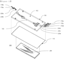
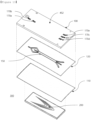
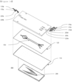
- the disposable separation chip may include an upper plate 100 and a first member 110.
- the upper plate 100 may be manufactured to be similar to a rectangular board of a low height.
- the first member 110 may be similar to a plate formed with a very thin thickness compared to its length and width, and may be produced with film or tape.
- the first member 110 may be coupled to a lower portion of the upper plate 100. More particularly, the first member 110 may be coupled to the upper plate 100 using an adhesive disposed on a lower surface of the upper plate 100. In this case, since a channel 150 is formed on the lower surface of the upper plate 100, the adhesive may be applied only to a portion except for the channel 150 on the lower surface of the upper plate 100, and the lower surface of the channel 150 thereby may be formed by the first member 110.
- the channel 150 may be formed in an intaglio shape in which the lower surface of the upper plate 100 is concavely dug.
- the channel may be formed through an embossed shape formed on a mold in an intaglio shape at a corresponding position of the upper plate 100 when producing the upper plate 100, and may also be formed by making the lower surface of the upper plate 100 flat, and then mechanically processing or chemically etching the lower surface.
- the channel 150 may be formed in various shapes according to its purpose.
- the coupling portion 170 is located on the upper plate and coupled with a tubing, and thus may serve to supply a buffer solution or a microfluid supplied from the tubing to the channel 150.
- the conventional coupling portion is formed in a shape penetrating the upper portion and the lower portion of the upper plate, and then a pipe is inserted such that the tubing is coupled to the exposed surface of the pipe and used.
- the three stages of tubing-pipe-penetration portion need to be passed to supply the microfluid to the channel.
- loss of cells supplied by the microfluid increases as the number of connecting portions of each component increases. In the case of the present invention, it is possible to minimize the loss of cells by using only two steps of tubing-coupling portion for the connection.
- the coupling portion may include a depression portion formed on the upper surface of the upper plate; a pipe portion located inside the depression portion and inserted into the tubing; and a connection portion for connecting such that an inner circumferential surface of the pipe portion extends to be connected to the channel.
- the depression portion 171 is a place where the pipe portion 172 protruding outside is formed, and may be formed in a shape in which a part of the upper plate 100 of the separation chip is depressed. Through this, the pipe portion 172 may be formed to have a short length and thereby can prevent damages thereof caused from protruding outside wherein manufacture and transportation of the separated chip portion may be easy due to its stacking and storing.
- the pipe portion 172 is installed extending upward from the lowest point inside the depression portion 171 (see FIG. 2 ), and as described above, and it is preferably formed such that the height of an uppermost end equals to or is lower than the upper surface of the upper plate 100.
- the pipe portion 172 forms preferably an acute angle with respect to the upper surface of the upper plate, and the advantages thereof are as follows.
- an angle between an injection hole and syringe is a right angle or close to a right angle.
- the pressure of the solution acts greatly, and the solution permeates between the components forming the upper plate, for example, the members coupled to the upper plate.
- the solution is injected in slope such that the pressure of the solution does not significantly act on the upper plate, the lower plate, or the first member when injecting the solution into the separation chip, thereby increasing the durability of the chip itself.
- the separation chip of the present invention since the solution is injected slantly and flows through the channel, a directionality of the solution injection may be secured so that the solution may flow smoothly through the channel.
- the chip according to the related art has the following problems because the tubing is performed in a vertical direction through an injection hole or an outlet.
- the tubing is formed of PDMS (polydimethylsiloxane, a type of synthetic lubber material) material, which is generally connected to the channel, and when lens moves to the injection hole or the outlet, interference between the lens and the tubing occurs.
- PDMS polydimethylsiloxane, a type of synthetic lubber material
- the interference between the lens and the tubing may eventually change or obstruct the flow of the solution in the tubing, or increase the possibility that the tubing departs from the injection hole or the outlet.
- a tubing in the separation chip of the present invention fits into a pipe having an acute angle with the upper surface of the upper plate.
- CTCs blood tumor cells
- a remaining probability of cells near the injection hole or at the rear (i.e., a rear part) of the injection hole is high.
- a vertical pressure hardly acts when injecting the solution.
- connection portion 173 is a portion for connecting such that the inner circumferential surface of the pipe portion 172 extends to be connected to the channel 150 so that the fluid supplied from the pipe portion 172 is supplied to the channel. Accordingly, an internal shape of the connection portion 173 may be configured such that the inner circumferential surface of the pipe portion and the channel portion may be smoothly connected, and thereby it is possible to minimize a resistance when supplying the fluid (buffer solution or fine liquid) supplied from the pipe portion to the channel direction (see FIG. 3 ).
- an upper end of the pipe portion 172 may be cut at the same angle as the upper surface of the upper plate 100 (see FIG. 3 ). That is, the upper surface of the pipe portion 172 is not cut in a direction perpendicular to the center of the pipe portion, but is cut in a direction horizontal to the upper surface, and thus the upper surface of the pipe portion and the center of the pipe portion may form an acute angle. It is possible thereby to smoothly insert the tubing, and prevent the tubing from departing due to fluid pressure when supplying the fluid to the tubing by increasing the outer surface area of the pipe being in contact with the inner circumferential surface of the tubing.
- a stopper portion 174 having a diameter equal to or greater than the tubing is formed on the outer circumferential surface of the pipe portion so that the tubing may be inserted at a predetermined depth.
- the pipe portion 172 may be inserted into inside the tubing.
- the lower surface of the pipe portion 172 since the lower surface of the pipe portion 172 is in contact with the depression portion 171, the lower surface of the pipe portion 172 may be in contact with the depression portion in a shape forming an acute angle.
- one side of the tubing may contact the surface of the depression portion first, and the other side may be located at the middle of the pipe portion 172.
- the stopper portion 174 may have a diameter that is equal to or greater than the outer circumferential surface of the tubing, and it is formed preferably perpendicular to the center of the pipe portion.
- the coupling portion 170 including the pipe portion 172 may be integrally formed with the upper plate.
- the upper plate is manufactured by coupling with a metal pipe portion, which is separately manufactured after the manufacture of the upper plate.
- the pipe portion is inserted into a hole formed on the upper plate, and supplies the fluid to the channel direction.
- a gap may be produced between the inserted pipe and the hole, and thus it needs to perform a waterproof treatment between the pipe and the hole so that sample or buffer solution does not leak.
- the pipe inserted into the hole is separately manufactured, which may act as a factor that increase the unit cost and the manufacture cost of the disposable separation chip.
- the upper plate and the coupling portion are integrally manufactured when manufacturing a mold and the number of parts and unit cost of the disposable separation chip may be reduced wherein as the number of the connection portions and the disposable separation chip is reduced, the separation efficiency may be improved (the more connection portions, the more cell loss).
- the upper plate of the disposable separation chip using a precision mold, it is possible to improve the stable performance of the separation chip by increasing the surface roughness of all paths through which the sample passes, such as a hole, a pipe, a channel, and the like.
- the disposable separation chip includes an upper plate 100 including a channel and a first member 110, and the first member 110 may be coupled to the lower end surface of the upper plate 100.
- the upper plate 100 may be manufactured in a shape similar to a rectangular plate having a low height, and the first member 110 may be manufactured in the shape of sheet or film having a very thin thickness compared to the length and width wherein they may be manufactured of various materials such as PEN, PET, PC, etc. depending on the use or the condition.
- the disposable separation chip according to the present invention may be manufactured of plastic.
- the upper plate may be manufactured of plastic.
- the first member and the lower plate may also be manufactured of plastic.
- PC polycarbonate
- PMMA polymethylmethacrylate
- the upper plate and the first member may be coupled by various methods such as (1) high frequency welding (2) ultrasonic welding (3) thermal fusion.
- the coupling portion located in the separation chip will be described based on an embodiment as follows.
- a mixed solution injection hole through which a mixed solution is injected and a buffer solution injection hole through which buffer solution such as saline solution is injected are located on one side of the upper plate.
- a magnetic bead discharge hole through which magnetic beads are discharged and other particle discharge hole through which other particles are discharged are located on the other side of the upper plate in the coupling portion located in the separation chip of the present invention.
- the plurality of coupling portions are formed to be connected to the channel, and the coupling portion may be integrally manufactured with the upper plate as described above.
- a hole 220a through which a sample (microfluid including blood) is injected and a hole 220b through which a buffer solution such as a saline solution is injected may be located on one side of the upper plate.
- a hole 220c through which a separated sample is discharged and holes 220d and 220e through which the buffer solution including other samples is discharged are located on the other side of the upper plate 450.
- the plurality of holes 220a to 220e are formed to be connected to the channel, and the pipe 170 is positioned in the holes 220a to 220e in an integrated shape.
- a wire pattern may be disposed at a specific position of the channel 150 as a hole for alignment with a wire pattern chip.
- the wire pattern is formed to have a parabolic shape from one side to the other side of the lower chip.
- the wire pattern is located at a third channel, which is a part of the channel where cell separation is performed.
- the wire pattern is located from a starting point to an end point of the third channel wherein a parabolic shape is formed from one side to the other side of the lower chip, that is, it can be said that the vertex of the wire pattern is formed close to the end point of the third channel.
- the disposable separation chip according to the present invention includes a channel 150 formed on the lower surface of an upper plate 100, wherein the channel 150 may be formed by engraving the lower surface of the upper plate in a concave shape.
- the existing channel is formed by manufacturing the lower surface of the upper plate to be flattened and deleted in a channel shape, and then attaching a member that was engraved in a conduit shape on one side.
- defects may occur depending on the position where the member is attached, and a phenomenon may occur that a leakage occurs in the portion connecting the upper plate and the member, or cells are attached thereto and thus lost.
- the present invention enables the formation of the channel only by coupling the first member to the lower surface of the upper plate on which a channel-shaped intaglio is formed, thereby fundamentally preventing the loss or leakage of the cells.
- leakage of the channel may be determined depending on the coupling force between the first member and the lower plate.
- the upper plate is manufactured in a plane shape, when coupling the upper plate and the lower plate, there is a case in which the coupling force of the central portion has decreased, thereby resulting in the occurrence of leakage.
- the thickness of a central portion is thicker than the thickness of both side surfaces, and thus when pressing an edge portion for coupling the upper plate and the second plate, the central portion in which the channel is formed is pressed, thereby minimizing defects due to leakage.
- the channel located at the center may also be deformed, and considering this, it is preferable to form the central portion of the channel to be shallow when forming the channel.
- a pressing means for compressing the separation chip to the direction of the lower chip may be included at the upper and lower ends of both side surfaces of the upper plate.
- the pressing means presses the upper plate to the direction of the lower plate.
- the pressing means presses the upper plate to the direction of the lower plate, and at the same time allows the lower surface of the upper plate to be a straight shape wherein it more presses the channel portion than the side surface portion of the upper plate.
- the pressing means may be used without limitation as long as the lower plate is coupled by pressing the upper plate, and preferably, and the pressing means may be a bolt and nut, clamp, or press that presses the upper surface of the upper plate downward and the like.
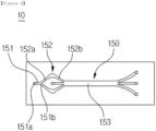
- a channel formed on the lower side of the upper plate may be formed as below (see FIG. 6 ).
- a first channel 151 connected to an injection hole 220a is located at the center of the upper plate 100 based on the width direction of the upper plate 100, and may be formed at one side of the upper plate 100 based on the length direction of the upper plate 100.
- one side 151a of the first channel may be connected to an injection coupling portion 220a.
- a second channel 152 includes a plurality of branched channels, and the branched channel located above based on the width direction of the upper plate will be described in the following description.
- the second channel 152 may include a first portion 152a and a second portion 152b.
- the first portion 152a of the second channel 152 may be extended to have a predetermined length upward on the right side of the first channel 151.
- the second portion 152b of the second channel 152 is connected to the first portion 152a of the second channel 152, and may be extended downward on the right side of the other side of the first portion 152a of the second channel to have a predetermined length.
- the first portion 152a of the second channel may be formed to increase gradually its width as it approaches closely to the second portion 152b of the second channel 152.
- the second portion 152b of the second channel may be formed to decrease gradually its width as it approaches closely to a third channel 153 being connected to the second portion 152b of the second channel.
- the width of the second channel 152 is maintained constantly, since the cells are moved only to one wall of the channel after having passed through the portion where the other side of the first part 152a of the second channel and the one side of the second part 152a of the second channel are connected, i.e. the portion where the channel is bent, the redistribution effect may not appear or may be reduced.
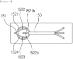
- the separation chip according Embodiment 2 of the present invention including a channel formed on the lower side of the upper plate may be formed as follows (see FIG. 7 ) .
- a first channel 151being connected to an injection hole 220a is located at the center of the upper plate 100 based on the width direction of the upper plate 100, and may be formed at one side of the upper plate 100 based on the length direction of the upper plate 100.
- the first channel 151 is formed to be shorter in length than the second channel 152.
- the second channel 152 being connected to the first channel 151 includes a plurality of branched channels.
- the second channel 152 may be formed to have an arc shape as shown in the drawing.
- the second channel 152 is located above and below the center of the upper plate 100 based on the width direction of the upper plate 100, and may be branched into a plurality of channels.
- two or more branched channels may be provided above and two or more branched channels may be provided below.
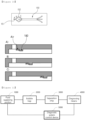
- the separation chip according to Embodiment 3 of the present invention including a channel formed on one side of the upper plate may be formed as follows (see FIGS. 8 and 9 ).
- a plurality of branched channels forming the second channel 152 may be combined into one before some of the branched channels becomes connected to the third channel 153. That is, hereinafter, the second channel will be described based on the case in which the second channel is located above and below the center of the upper plate 100 based on the width direction of the upper plate 100, and in this case, when viewed from the center of the width of the upper plate, two branched channels are provided above and also two branched channels are provided below.
- the branched second channel 152 is referred to as a 2-1 channel 1521 to a 2-4 channel 1524.
- a part of the 2-1channel 1521 and a part of the 2-2 channel 1522 are combined each other before the 2-2 channel 1522 becomes connected to a third channel 153 and thus form one channel.
- the part of the 2-1 channel means a part adjacent to the third channel among the 2-1 channel.
- a part 1522b of the 2-2 channel means a part adjacent to the third channel 153 among the 2-2 channel 1522.
- a part 1521b of the 2-1 channel and a part 1522b of the 2-2 channel are combined into one and then may be connected to the third channel 153.
- the separation chip 10 includes a filter that may be located on the channel 150.
- a filter may be located on a first channel 151 or a second channel 152.
- a plurality of filters may be located on the second channel 152, and specifically, the filters may be located on a first portion 152a of the second channel and a second portion 152b of the second channel, respectively.
- one or more filters may be located on the first channel 151 as well.
- the filter is connected to the channel 150, and has a predetermined space.
- the filter performs the following roles.
- gas (air) contained in a solution may be removed. That is, a removal method based on the specific gravity of the solution and the gas is selected.
- the gas located above the solution due to the difference in specific gravity when a solution containing gas passes through the filter is connected to the channel, and is trapped in the filter having a predetermined space, so that the gas contained in the solution is removed. Accordingly, when viewed from the cross-section of the disposable separation chip 10 according to the present invention, it is preferable that the filter is located on the upper part of the channel 150.
- a protrusion 180 may be located in the separation chip 10 of the present invention (see FIG. 10 ).
- the channel 150 formed in the separation chip 10 of the present invention may include the first channel 151.
- the channel 150 is connected to the first channel 151, and may include the second channel (152) branched in plural.
- a plurality of protrusions 180 may be located on the first channel 151 or the second channel 152.
- the protrusion 180 may be located on the lower portion of the upper plate in which the channel 150 is formed. That is, it has been described above that to form the channel 150 on the lower portion of the upper plate, a concave groove may be formed on a portion of the upper plate.
- a concave groove may be formed in the remaining part except for the protrusion 180 in the width of the first channel 151.
- a part of the protrusion is cut to form a groove through which a fluid can flow at the lower portion, but it may be manufactured in a shape in which a protrusion is formed at the upper portion.
- the roles of the protrusion 180 are as below. The present invention is described based on a case in which a plurality of protrusions 180 are formed on the first channel 151.
- the distance between one protrusion and the other adjacent protrusion may be formed to be smaller than the size of air particle mixed in the solution.
- the protrusion is located in the upper portion of the channel, thereby effectively removing air particles located in the upper portion due to the different in specific gravity.
- the protrusion 180 described above may has various shapes, such as rectangle, circle, or rhombus, within a range capable of filtering air particles.
- the protrusion 180 located in the first channel 151 or the second channel 152 may also be formed to have not only one row but also two or more rows. That is, the protrusion 180 may include a first protrusion and a second protrusion located below or in a side of the first protrusion.
- the present invention further provides a microfluidic based diagnostic system including the disposable separation chip.
- the microfluidic based diagnostic system may include a fluid supplying portion for supplying a buffer solution or a microfluid; a microfluid bubble trap for removing bubbles contained in a fluid supplied from the fluid supplying portion; a disposable separation chip for mixing or separating the fluid passing through the microfluid bubble trap; a diagnosing means for analyzing the microfluid passing through the separation chip; and a diagnostic system control device for controlling the diagnostic system.
- the fluid supplying portion 1000 is provided with a pump for supplying the microfluid and a tube and valve for transporting the fluid, and may perform stable fluid supply through appropriate flow rate control.
- the bubble trap 2000 is provided with a bubble trap body, an inlet and an outlet, and may prevent microbubbles from flowing into the channel by trapping the microbubbles introduced from the fluid supplying unit 1000 inside the bubble trap.
- the separation chip 3000 is manufactured of materials such as plastic or plastic and glass (ceramic), which is composed of an inlet through which fluid is introduced, an outlet, a fine channel, and the like, and may be able to perform separation, measurement, incubation, and analysis.
- materials such as plastic or plastic and glass (ceramic), which is composed of an inlet through which fluid is introduced, an outlet, a fine channel, and the like, and may be able to perform separation, measurement, incubation, and analysis.
- the diagnosing means 4000 is provided with an optical system including a fluorescence system and high-performance camera, and may perform fluorescence analysis, single cell analysis, protein analysis, and the like.
- the diagnostic system control device 5000 is provided with a hardware including a central processing unit (CPU) and input/output devices (e.g., flow rate sensor, pinch valve, touch interface, etc.), and may control communication and tuning between each input/output device and perform analysis on data collected from a diagnosis means 4000.
- CPU central processing unit
- input/output devices e.g., flow rate sensor, pinch valve, touch interface, etc.
- the microfluidic based diagnostic system of the present invention may include a separation chip 3000.
- the accuracy of the diagnostic system based on microfluid may be greatly influenced by the presence or absence of bubbles in the microfluid. Therefore, in the present invention, the bubbles of fluid are removed using a bubble trap 2000 and supplied to the separation chip 3000, thereby greatly improving the reliability of the diagnostic system (see FIG. 11 ).
Landscapes
- Chemical & Material Sciences (AREA)
- Health & Medical Sciences (AREA)
- General Health & Medical Sciences (AREA)
- Analytical Chemistry (AREA)
- Physics & Mathematics (AREA)
- Hematology (AREA)
- Clinical Laboratory Science (AREA)
- Chemical Kinetics & Catalysis (AREA)
- Dispersion Chemistry (AREA)
- Immunology (AREA)
- General Physics & Mathematics (AREA)
- Biochemistry (AREA)
- Life Sciences & Earth Sciences (AREA)
- Pathology (AREA)
- Fluid Mechanics (AREA)
- Apparatus Associated With Microorganisms And Enzymes (AREA)
- Investigating Or Analysing Biological Materials (AREA)
- Automatic Analysis And Handling Materials Therefor (AREA)
Applications Claiming Priority (2)
| Application Number | Priority Date | Filing Date | Title |
|---|---|---|---|
| KR1020210138208A KR102399411B1 (ko) | 2021-10-18 | 2021-10-18 | 일회용 분리칩 |
| PCT/KR2022/015675 WO2023068684A1 (ko) | 2021-10-18 | 2022-10-17 | 일회용 분리칩 |
Publications (2)
| Publication Number | Publication Date |
|---|---|
| EP4400845A1 true EP4400845A1 (de) | 2024-07-17 |
| EP4400845A4 EP4400845A4 (de) | 2025-10-15 |
Family
ID=81800866
Family Applications (1)
| Application Number | Title | Priority Date | Filing Date |
|---|---|---|---|
| EP22883907.2A Pending EP4400845A4 (de) | 2021-10-18 | 2022-10-17 | Einweg-trennchip |
Country Status (6)
| Country | Link |
|---|---|
| US (1) | US12605709B2 (de) |
| EP (1) | EP4400845A4 (de) |
| JP (1) | JP7788763B2 (de) |
| KR (1) | KR102399411B1 (de) |
| CN (1) | CN118369583A (de) |
| WO (1) | WO2023068684A1 (de) |
Families Citing this family (1)
| Publication number | Priority date | Publication date | Assignee | Title |
|---|---|---|---|---|
| KR102399411B1 (ko) * | 2021-10-18 | 2022-05-18 | 주식회사 지노바이오 | 일회용 분리칩 |
Family Cites Families (19)
| Publication number | Priority date | Publication date | Assignee | Title |
|---|---|---|---|---|
| US6664104B2 (en) | 1999-06-25 | 2003-12-16 | Cepheid | Device incorporating a microfluidic chip for separating analyte from a sample |
| JP2007165653A (ja) | 2005-12-14 | 2007-06-28 | Ses Co Ltd | 気泡除去方法及び気泡除去装置 |
| KR100900511B1 (ko) * | 2007-07-23 | 2009-06-03 | 주식회사 디지탈바이오테크놀러지 | 유체분석용 칩 |
| JP5278913B2 (ja) * | 2007-08-01 | 2013-09-04 | 国立大学法人東京農工大学 | 単一細胞捕捉用マイクロ流路デバイス |
| JP2010151777A (ja) * | 2008-11-19 | 2010-07-08 | Sony Corp | 微小粒子解析装置、微小粒子解析用マイクロチップ及び微小粒子解析方法 |
| KR101070311B1 (ko) * | 2009-01-29 | 2011-10-06 | 한국표준과학연구원 | 마이크로플루이딕스 칩을 위한 플랫폼 장치 |
| DE202010001422U1 (de) * | 2010-01-27 | 2010-04-08 | Bürkert Werke GmbH | Fluidische Steckverbindung |
| US11931740B2 (en) * | 2012-02-13 | 2024-03-19 | Neumodx Molecular, Inc. | System and method for processing and detecting nucleic acids |
| KR101175594B1 (ko) * | 2012-05-14 | 2012-08-21 | 주식회사 나노엔텍 | 샘플분석용 칩 |
| JP5928892B2 (ja) | 2012-07-30 | 2016-06-01 | 株式会社リコー | 泡除去装置及び泡除去方法 |
| KR102140036B1 (ko) | 2013-11-21 | 2020-07-31 | 인제대학교 산학협력단 | 미세입자 분리 및 포획을 위한 장치 |
| KR101559161B1 (ko) | 2014-07-15 | 2015-11-10 | 포항공과대학교 산학협력단 | 미세 유체칩으로 유입되는 시료의 기포 및 맥동성 제거를 위한 유동제어 장치, 이를 이용한 유동제어 방법, 및 이를 포함하는 유동제어 시스템 |
| KR101700228B1 (ko) | 2014-12-03 | 2017-02-14 | 한국과학기술원 | 세포 분리칩 및 이를 이용한 세포 분리 방법 |
| KR101667351B1 (ko) * | 2016-02-18 | 2016-10-18 | 주식회사 지노바이오 | 일회용 분리칩 |
| US10758906B2 (en) * | 2016-02-18 | 2020-09-01 | Genobio, Inc. | Cell separation chip and system |
| KR102039230B1 (ko) * | 2017-12-13 | 2019-10-31 | 인제대학교 산학협력단 | 버블 유입 방지용 시료주입 장치 |
| KR102048617B1 (ko) * | 2017-12-28 | 2020-01-08 | 주식회사 지노바이오 | 분리칩 |
| KR101893114B1 (ko) * | 2018-01-19 | 2018-08-30 | 삼성전자 주식회사 | 기체 버블 트랩 기능을 갖는 미세 유체 공급소자 |
| KR102399411B1 (ko) * | 2021-10-18 | 2022-05-18 | 주식회사 지노바이오 | 일회용 분리칩 |
-
2021
- 2021-10-18 KR KR1020210138208A patent/KR102399411B1/ko active Active
-
2022
- 2022-10-17 WO PCT/KR2022/015675 patent/WO2023068684A1/ko not_active Ceased
- 2022-10-17 CN CN202280070339.1A patent/CN118369583A/zh active Pending
- 2022-10-17 EP EP22883907.2A patent/EP4400845A4/de active Pending
- 2022-10-17 JP JP2024517076A patent/JP7788763B2/ja active Active
- 2022-10-17 US US17/928,272 patent/US12605709B2/en active Active
Also Published As
| Publication number | Publication date |
|---|---|
| WO2023068684A1 (ko) | 2023-04-27 |
| JP7788763B2 (ja) | 2025-12-19 |
| KR102399411B1 (ko) | 2022-05-18 |
| EP4400845A4 (de) | 2025-10-15 |
| JP2024534473A (ja) | 2024-09-20 |
| US12605709B2 (en) | 2026-04-21 |
| CN118369583A (zh) | 2024-07-19 |
| US20240116052A1 (en) | 2024-04-11 |
Similar Documents
| Publication | Publication Date | Title |
|---|---|---|
| AU2023285752A1 (en) | Polymer microfiltration devices, methods of manufacturing the same and the uses of the microfiltration devices | |
| US20200070167A1 (en) | Processing systems for isolating and enumerating cells or particles | |
| EP3421968A1 (de) | Optische partikelanalyse unter verwendung einer trägerflüssigkeit | |
| US9908117B2 (en) | Microfluidic separation device, separation method using the same and kit for separating circulating rare cells from blood using the same | |
| US20220251497A1 (en) | Microfluidic chip suitable for capturing circulating tumour cells | |
| EP2020598A1 (de) | Mikrokanal zur trennung von blutplasma | |
| KR101667351B1 (ko) | 일회용 분리칩 | |
| US12605709B2 (en) | Disposable separation chip | |
| Quan et al. | An ultra-thin silicon nitride membrane for label-free CTCs isolation from whole blood with low WBC residue | |
| US20210354141A1 (en) | Microfluidic particle sorting apparatus and manufacturing method thereof | |
| JP6164375B2 (ja) | 細胞捕捉デバイス | |
| CN122038106A (zh) | 微尺度细胞过滤器 | |
| JP7760804B1 (ja) | 流路デバイス | |
| US10758906B2 (en) | Cell separation chip and system | |
| US20230383239A1 (en) | Microscale cell filter | |
| KR20240047883A (ko) | 셀 분리 장치 | |
| CN108663258A (zh) | 一种循环肿瘤细胞筛选芯片及方法 | |
| JP5849466B2 (ja) | 分離装置 | |
| CN112251319A (zh) | 一种非小细胞肺癌循环肿瘤细胞分离系统及方法 | |
| TWM581592U (zh) | 具有彎曲流道的微流道晶片及微流道結構 |
Legal Events
| Date | Code | Title | Description |
|---|---|---|---|
| STAA | Information on the status of an ep patent application or granted ep patent |
Free format text: STATUS: THE INTERNATIONAL PUBLICATION HAS BEEN MADE |
|
| PUAI | Public reference made under article 153(3) epc to a published international application that has entered the european phase |
Free format text: ORIGINAL CODE: 0009012 |
|
| STAA | Information on the status of an ep patent application or granted ep patent |
Free format text: STATUS: REQUEST FOR EXAMINATION WAS MADE |
|
| 17P | Request for examination filed |
Effective date: 20240411 |
|
| AK | Designated contracting states |
Kind code of ref document: A1 Designated state(s): AL AT BE BG CH CY CZ DE DK EE ES FI FR GB GR HR HU IE IS IT LI LT LU LV MC ME MK MT NL NO PL PT RO RS SE SI SK SM TR |
|
| DAV | Request for validation of the european patent (deleted) | ||
| DAX | Request for extension of the european patent (deleted) | ||
| A4 | Supplementary search report drawn up and despatched |
Effective date: 20250917 |
|
| RIC1 | Information provided on ipc code assigned before grant |
Ipc: G01N 35/00 20060101AFI20250911BHEP Ipc: G01N 35/08 20060101ALI20250911BHEP Ipc: B01L 3/00 20060101ALI20250911BHEP |