EP4400611A1 - Kontinuierliches wärmebehandlungssystem für einen hochdruckflüssigkeitsspeicherbehälter - Google Patents
Kontinuierliches wärmebehandlungssystem für einen hochdruckflüssigkeitsspeicherbehälter Download PDFInfo
- Publication number
- EP4400611A1 EP4400611A1 EP23801653.9A EP23801653A EP4400611A1 EP 4400611 A1 EP4400611 A1 EP 4400611A1 EP 23801653 A EP23801653 A EP 23801653A EP 4400611 A1 EP4400611 A1 EP 4400611A1
- Authority
- EP
- European Patent Office
- Prior art keywords
- heat treatment
- pressure fluid
- fluid storage
- storage container
- cooling
- Prior art date
- Legal status (The legal status is an assumption and is not a legal conclusion. Google has not performed a legal analysis and makes no representation as to the accuracy of the status listed.)
- Withdrawn
Links
Images




Classifications
-
- F—MECHANICAL ENGINEERING; LIGHTING; HEATING; WEAPONS; BLASTING
- F27—FURNACES; KILNS; OVENS; RETORTS
- F27B—FURNACES, KILNS, OVENS OR RETORTS IN GENERAL; OPEN SINTERING OR LIKE APPARATUS
- F27B9/00—Furnaces through which the charge is moved mechanically, e.g. of tunnel type; Similar furnaces in which the charge moves by gravity
- F27B9/14—Furnaces through which the charge is moved mechanically, e.g. of tunnel type; Similar furnaces in which the charge moves by gravity characterised by the path of the charge during treatment; characterised by the means by which the charge is moved during treatment
- F27B9/20—Furnaces through which the charge is moved mechanically, e.g. of tunnel type; Similar furnaces in which the charge moves by gravity characterised by the path of the charge during treatment; characterised by the means by which the charge is moved during treatment the charge moving in a substantially straight path
- F27B9/24—Furnaces through which the charge is moved mechanically, e.g. of tunnel type; Similar furnaces in which the charge moves by gravity characterised by the path of the charge during treatment; characterised by the means by which the charge is moved during treatment the charge moving in a substantially straight path being carried by a conveyor
- F27B9/2407—Furnaces through which the charge is moved mechanically, e.g. of tunnel type; Similar furnaces in which the charge moves by gravity characterised by the path of the charge during treatment; characterised by the means by which the charge is moved during treatment the charge moving in a substantially straight path being carried by a conveyor the conveyor being constituted by rollers (roller hearth furnace)
-
- C—CHEMISTRY; METALLURGY
- C21—METALLURGY OF IRON
- C21D—MODIFYING THE PHYSICAL STRUCTURE OF FERROUS METALS; GENERAL DEVICES FOR HEAT TREATMENT OF FERROUS OR NON-FERROUS METALS OR ALLOYS; MAKING METAL MALLEABLE, e.g. BY DECARBURISATION OR TEMPERING
- C21D1/00—General methods or devices for heat treatment, e.g. annealing, hardening, quenching or tempering
- C21D1/62—Quenching devices
- C21D1/63—Quenching devices for bath quenching
-
- C—CHEMISTRY; METALLURGY
- C21—METALLURGY OF IRON
- C21D—MODIFYING THE PHYSICAL STRUCTURE OF FERROUS METALS; GENERAL DEVICES FOR HEAT TREATMENT OF FERROUS OR NON-FERROUS METALS OR ALLOYS; MAKING METAL MALLEABLE, e.g. BY DECARBURISATION OR TEMPERING
- C21D9/00—Heat treatment, e.g. annealing, hardening, quenching or tempering, adapted for particular articles; Furnaces therefor
- C21D9/0006—Details, accessories not peculiar to any of the following furnaces
- C21D9/0012—Rolls; Roll arrangements
-
- C—CHEMISTRY; METALLURGY
- C21—METALLURGY OF IRON
- C21D—MODIFYING THE PHYSICAL STRUCTURE OF FERROUS METALS; GENERAL DEVICES FOR HEAT TREATMENT OF FERROUS OR NON-FERROUS METALS OR ALLOYS; MAKING METAL MALLEABLE, e.g. BY DECARBURISATION OR TEMPERING
- C21D9/00—Heat treatment, e.g. annealing, hardening, quenching or tempering, adapted for particular articles; Furnaces therefor
- C21D9/0006—Details, accessories not peculiar to any of the following furnaces
- C21D9/0018—Details, accessories not peculiar to any of the following furnaces for charging, discharging or manipulation of charge
-
- C—CHEMISTRY; METALLURGY
- C21—METALLURGY OF IRON
- C21D—MODIFYING THE PHYSICAL STRUCTURE OF FERROUS METALS; GENERAL DEVICES FOR HEAT TREATMENT OF FERROUS OR NON-FERROUS METALS OR ALLOYS; MAKING METAL MALLEABLE, e.g. BY DECARBURISATION OR TEMPERING
- C21D9/00—Heat treatment, e.g. annealing, hardening, quenching or tempering, adapted for particular articles; Furnaces therefor
- C21D9/0056—Furnaces through which the charge is moved in a horizontal straight path
-
- C—CHEMISTRY; METALLURGY
- C21—METALLURGY OF IRON
- C21D—MODIFYING THE PHYSICAL STRUCTURE OF FERROUS METALS; GENERAL DEVICES FOR HEAT TREATMENT OF FERROUS OR NON-FERROUS METALS OR ALLOYS; MAKING METAL MALLEABLE, e.g. BY DECARBURISATION OR TEMPERING
- C21D9/00—Heat treatment, e.g. annealing, hardening, quenching or tempering, adapted for particular articles; Furnaces therefor
- C21D9/0062—Heat-treating apparatus with a cooling or quenching zone
-
- C—CHEMISTRY; METALLURGY
- C21—METALLURGY OF IRON
- C21D—MODIFYING THE PHYSICAL STRUCTURE OF FERROUS METALS; GENERAL DEVICES FOR HEAT TREATMENT OF FERROUS OR NON-FERROUS METALS OR ALLOYS; MAKING METAL MALLEABLE, e.g. BY DECARBURISATION OR TEMPERING
- C21D9/00—Heat treatment, e.g. annealing, hardening, quenching or tempering, adapted for particular articles; Furnaces therefor
- C21D9/08—Heat treatment, e.g. annealing, hardening, quenching or tempering, adapted for particular articles; Furnaces therefor for tubular bodies or pipes
-
- C—CHEMISTRY; METALLURGY
- C21—METALLURGY OF IRON
- C21D—MODIFYING THE PHYSICAL STRUCTURE OF FERROUS METALS; GENERAL DEVICES FOR HEAT TREATMENT OF FERROUS OR NON-FERROUS METALS OR ALLOYS; MAKING METAL MALLEABLE, e.g. BY DECARBURISATION OR TEMPERING
- C21D9/00—Heat treatment, e.g. annealing, hardening, quenching or tempering, adapted for particular articles; Furnaces therefor
- C21D9/08—Heat treatment, e.g. annealing, hardening, quenching or tempering, adapted for particular articles; Furnaces therefor for tubular bodies or pipes
- C21D9/085—Cooling or quenching
-
- F—MECHANICAL ENGINEERING; LIGHTING; HEATING; WEAPONS; BLASTING
- F27—FURNACES; KILNS; OVENS; RETORTS
- F27B—FURNACES, KILNS, OVENS OR RETORTS IN GENERAL; OPEN SINTERING OR LIKE APPARATUS
- F27B9/00—Furnaces through which the charge is moved mechanically, e.g. of tunnel type; Similar furnaces in which the charge moves by gravity
- F27B9/02—Furnaces through which the charge is moved mechanically, e.g. of tunnel type; Similar furnaces in which the charge moves by gravity of multiple-track type; of multiple-chamber type; Combinations of furnaces
- F27B9/028—Multi-chamber type furnaces
-
- F—MECHANICAL ENGINEERING; LIGHTING; HEATING; WEAPONS; BLASTING
- F27—FURNACES; KILNS; OVENS; RETORTS
- F27B—FURNACES, KILNS, OVENS OR RETORTS IN GENERAL; OPEN SINTERING OR LIKE APPARATUS
- F27B9/00—Furnaces through which the charge is moved mechanically, e.g. of tunnel type; Similar furnaces in which the charge moves by gravity
- F27B9/04—Furnaces through which the charge is moved mechanically, e.g. of tunnel type; Similar furnaces in which the charge moves by gravity adapted for treating the charge in vacuum or special atmosphere
- F27B9/045—Furnaces with controlled atmosphere
-
- F—MECHANICAL ENGINEERING; LIGHTING; HEATING; WEAPONS; BLASTING
- F27—FURNACES; KILNS; OVENS; RETORTS
- F27B—FURNACES, KILNS, OVENS OR RETORTS IN GENERAL; OPEN SINTERING OR LIKE APPARATUS
- F27B9/00—Furnaces through which the charge is moved mechanically, e.g. of tunnel type; Similar furnaces in which the charge moves by gravity
- F27B9/14—Furnaces through which the charge is moved mechanically, e.g. of tunnel type; Similar furnaces in which the charge moves by gravity characterised by the path of the charge during treatment; characterised by the means by which the charge is moved during treatment
- F27B9/20—Furnaces through which the charge is moved mechanically, e.g. of tunnel type; Similar furnaces in which the charge moves by gravity characterised by the path of the charge during treatment; characterised by the means by which the charge is moved during treatment the charge moving in a substantially straight path
-
- F—MECHANICAL ENGINEERING; LIGHTING; HEATING; WEAPONS; BLASTING
- F27—FURNACES; KILNS; OVENS; RETORTS
- F27B—FURNACES, KILNS, OVENS OR RETORTS IN GENERAL; OPEN SINTERING OR LIKE APPARATUS
- F27B9/00—Furnaces through which the charge is moved mechanically, e.g. of tunnel type; Similar furnaces in which the charge moves by gravity
- F27B9/14—Furnaces through which the charge is moved mechanically, e.g. of tunnel type; Similar furnaces in which the charge moves by gravity characterised by the path of the charge during treatment; characterised by the means by which the charge is moved during treatment
- F27B9/20—Furnaces through which the charge is moved mechanically, e.g. of tunnel type; Similar furnaces in which the charge moves by gravity characterised by the path of the charge during treatment; characterised by the means by which the charge is moved during treatment the charge moving in a substantially straight path
- F27B9/24—Furnaces through which the charge is moved mechanically, e.g. of tunnel type; Similar furnaces in which the charge moves by gravity characterised by the path of the charge during treatment; characterised by the means by which the charge is moved during treatment the charge moving in a substantially straight path being carried by a conveyor
- F27B9/2469—Furnaces through which the charge is moved mechanically, e.g. of tunnel type; Similar furnaces in which the charge moves by gravity characterised by the path of the charge during treatment; characterised by the means by which the charge is moved during treatment the charge moving in a substantially straight path being carried by a conveyor the conveyor being constituted by rollable bodies
-
- F—MECHANICAL ENGINEERING; LIGHTING; HEATING; WEAPONS; BLASTING
- F27—FURNACES; KILNS; OVENS; RETORTS
- F27B—FURNACES, KILNS, OVENS OR RETORTS IN GENERAL; OPEN SINTERING OR LIKE APPARATUS
- F27B9/00—Furnaces through which the charge is moved mechanically, e.g. of tunnel type; Similar furnaces in which the charge moves by gravity
- F27B9/30—Details, accessories or equipment specially adapted for furnaces of these types
- F27B9/38—Arrangements of devices for charging
-
- F—MECHANICAL ENGINEERING; LIGHTING; HEATING; WEAPONS; BLASTING
- F27—FURNACES; KILNS; OVENS; RETORTS
- F27B—FURNACES, KILNS, OVENS OR RETORTS IN GENERAL; OPEN SINTERING OR LIKE APPARATUS
- F27B9/00—Furnaces through which the charge is moved mechanically, e.g. of tunnel type; Similar furnaces in which the charge moves by gravity
- F27B9/30—Details, accessories or equipment specially adapted for furnaces of these types
- F27B9/39—Arrangements of devices for discharging
-
- F—MECHANICAL ENGINEERING; LIGHTING; HEATING; WEAPONS; BLASTING
- F27—FURNACES; KILNS; OVENS; RETORTS
- F27D—DETAILS OR ACCESSORIES OF FURNACES, KILNS, OVENS OR RETORTS, IN SO FAR AS THEY ARE OF KINDS OCCURRING IN MORE THAN ONE KIND OF FURNACE
- F27D3/00—Charging; Discharging; Manipulation of charge
- F27D3/0024—Charging; Discharging; Manipulation of charge of metallic workpieces
-
- F—MECHANICAL ENGINEERING; LIGHTING; HEATING; WEAPONS; BLASTING
- F27—FURNACES; KILNS; OVENS; RETORTS
- F27D—DETAILS OR ACCESSORIES OF FURNACES, KILNS, OVENS OR RETORTS, IN SO FAR AS THEY ARE OF KINDS OCCURRING IN MORE THAN ONE KIND OF FURNACE
- F27D3/00—Charging; Discharging; Manipulation of charge
- F27D3/12—Travelling or movable supports or containers for the charge
-
- F—MECHANICAL ENGINEERING; LIGHTING; HEATING; WEAPONS; BLASTING
- F27—FURNACES; KILNS; OVENS; RETORTS
- F27D—DETAILS OR ACCESSORIES OF FURNACES, KILNS, OVENS OR RETORTS, IN SO FAR AS THEY ARE OF KINDS OCCURRING IN MORE THAN ONE KIND OF FURNACE
- F27D3/00—Charging; Discharging; Manipulation of charge
- F27D2003/0001—Positioning the charge
Definitions
- the present invention relates to a continuous heat treatment system for a high-pressure fluid storage container, and more specifically, to a continuous heat treatment system for a high-pressure fluid storage container, which consecutively performs a heat treatment process and a cooling process without performing a process of moving a high-pressure fluid storage container to a separate location in a process of manufacturing the high-pressure fluid storage container.
- a method of providing a pipe having a hollow therein, pressing the pipe while rotating the pipe through a spinning process to form an overall shape, and performing a quenching or tempering process is widely used to obtain physical characteristics of such a hydrogen storage container.
- a heat treatment process and a cooling process are repeatedly performed, and conventionally, a method of moving the hydrogen storage container from a heat treatment furnace to a cooling bath using a device such as a crane in order to perform the cooling process after the heat treatment process is completed.
- the conventional method since there is a difference in heat treatment quality according to the transfer time from the heat treatment furnace to the cooling bath, the conventional method has a problem that the product has large quality variations, and there is the possibility that an accident occurs during the transfer process.
- the present invention is directed to providing a continuous heat treatment system capable of consecutively performing a heat treatment process and a cooling process without performing a process of moving a high-pressure fluid storage container to a separate location in a process of manufacturing the high-pressure fluid storage container.
- One aspect of the present invention provides a continuous heat treatment system for a high-pressure fluid storage container, the continuous heat treatment system including a heat treatment apparatus including a first transfer unit which transfers a high-pressure fluid storage container, in which a high-pressure fluid is stored, in a longitudinal direction through the heat treatment space and a heating unit which heats an interior of the heat treatment space to a predetermined heat treatment temperature atmosphere and a cooling apparatus including a second transfer unit in which a lifting part is formed to continuously transfer the high-pressure fluid storage container transferred from the first transfer unit in the longitudinal direction, a lifting driving unit which vertically moves the lifting part, and a cooling bath in which a cooling space for accommodating a cooling fluid is formed and which is provided under the second transfer unit to cool the high-pressure fluid storage container located in the cooling space as the lifting part is lowered.
- a heat treatment apparatus including a first transfer unit which transfers a high-pressure fluid storage container, in which a high-pressure fluid is stored, in a longitudinal direction through the heat treatment space and a heating unit which heats an interior
- the heat treatment apparatus and the cooling apparatus may be provided as a plurality of treatment apparatuses and a plurality of cooling apparatuses, which are alternatively disposed.
- the first transfer unit and the second transfer unit may include a plurality of transfer roller modules disposed along a transfer path of the high-pressure fluid storage container and driving motors which provide rotational driving forces to the transfer roller modules.
- the driving motor of the first transfer unit and the driving motor of the second transfer unit may be synchronized with each other to control a speed.
- the driving motor may be provided outside the heat treatment furnace, and the first transfer unit may further include a driving force transmission module which transmits the rotational driving force of the driving motor to the transfer roller module.
- the transfer roller module may include driving bars rotated about a central axis by the rotational driving forces of the driving motor and a support roller which is provided to surround a circumference of the rotating bar, rotates with the rotating bar, and supports the high-pressure fluid storage container.
- the support rollers may include a first support part which supports one eccentric side portion of the high-pressure fluid storage container and a second support part which is connected to the first support part and supports the other eccentric side portion of the high-pressure fluid storage container, wherein the first support part and the second support part may each be formed to have an inclined surface inclined downward toward a connection point thereof to form a recessed groove.
- the support roller may be provided as a pair of support rollers on the rotating bar to have a line-symmetrical form and be spaced apart from each other.
- the pair of support rollers may further include third support parts which protrude in opposite directions and support one eccentric side portion and the other eccentric side portion of a high-pressure fluid storage container having specifications different from those of the high-pressure fluid storage container supported by the first support parts and the second support parts.
- the heat treatment apparatus may further include insulating units provided at an entrance and an exit of the heat treatment furnace to selectively block the entrance and exit of the heat treatment furnace.
- the insulating unit may include an insulating door provided to selectively block the entrance and exit of the heat treatment furnace and a door lifting motor which provide driving forces for vertically moving the insulating doors;
- the cooling apparatus may further include a chocking unit which blocks an open end of the high-pressure fluid storage container before the high-pressure fluid storage container located in the lifting part is lowered by the lifting part.
- the chocking unit may include a blocking member which is provided to selectively block the open end of the high-pressure fluid storage container and in which an air path through air flows is formed, a rotational connecting member which is connected to the blocking member and rotates the blocking member along a circular trajectory about a rotation axis at a predetermined location, a rotary motor which provides a rotational driving force to the rotational connecting member, and an air injection module which prevents the cooling fluid from entering the high-pressure fluid storage container by injecting air into the air path of the blocking member.
- the lifting driving unit may include a fixing frame provided above the lifting part, length adjusting modules provided under the fixing frame, connected to the lifting part, and whose length is variable, and a lifting driving motor which provides a driving force for adjusting the length of the length adjusting module.
- the cooling apparatus may further include a circulation pump unit which circulates the cooling fluid accommodated in the cooling bath in a direction parallel to a transfer direction of the high-pressure fluid storage container.
- a continuous heat treatment system for a high-pressure fluid storage container of the present invention for achieving the above objectives, since a high-pressure fluid storage container is transferred through a heat treatment furnace and a cooling bath in a process of continuously transferring the high-pressure fluid storage container using a first transfer unit and a second transfer unit, a heat treatment process and a cooling process can be consecutively performed, and thus there are advantages that an overall process time can be reduced and productivity can be greatly improved.
- quality variations can be minimized by greatly reducing a product processing waiting time, and an accident can be fundamentally prevented by omitting a process of moving a high-pressure fluid storage container to a separate location.
- first component region, layer, part, or the like
- first component region, layer, part, or the like
- FIG. 1 is a view illustrating the overall form of the continuous heat treatment system for a high-pressure fluid storage container according to one embodiment of the present invention.
- the continuous heat treatment system for a high-pressure fluid storage container mainly includes a heat treatment apparatus 100 and a cooling apparatus 500.
- the heat treatment apparatus 100 and the cooling apparatus 500 may be provided as a plurality of heat treatment apparatuses 100 and a plurality of cooling apparatuses 500, and the plurality of heat treatment apparatuses 100 and the plurality of cooling apparatuses 500 may be disposed alternately.
- the heat treatment apparatus 100 includes a heat treatment furnace 300, a first transfer unit 200, a heating unit 400, and insulating units 350.
- the cooling apparatus 500 includes a second transfer unit 600, a lifting driving unit 700, a cooling bath 800, and chocking units 900.
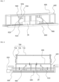
- FIGS. 2 to 5 are views illustrating forms and structures of components provided in the heat treatment apparatus 100 in the continuous heat treatment system for a high-pressure fluid storage container according to one embodiment of the present invention.
- a heat treatment space 310 is formed in the heat treatment furnace 300.
- the heat treatment furnace 300 may be formed in the form of a chamber having a shielded interior, but in the drawings, it is illustrated with an open side surface to show the structure thereof.
- the first transfer unit 200 transfers high-pressure fluid storage containers 10 and 20, in which high-pressure fluid is stored, through the heat treatment space 310 in a longitudinal direction.
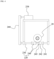
- the first transfer unit 200 includes a plurality of transfer roller modules 220 disposed along a transfer path of the high-pressure fluid storage containers 10 and 20, transfer frames 210 that secure both sides of the transfer roller modules 220, and driving motors 250 that provide rotational driving forces to the transfer roller modules 220.
- the driving motors 250 may be provided outside the heat treatment furnace 300, and the first transfer unit 200 may further include driving force transmission modules 260 for transmitting the rotational driving forces of the driving motors 250 to the transfer roller modules 220.
- the transfer roller modules 220 may be connected through a chain or the like so that the transfer roller modules 220 rotate in conjunction with each other, and each of the driving force transmission modules 260 may be formed in the form of a driving force transmission belt that transmits a rotational driving force of each of the driving motors 250 to any one of the transfer roller modules 220.
- the rotational driving force of the driving motor 250 is transmitted to all the transfer roller modules 220, and the first transfer unit 200 may move the high-pressure fluid storage containers 10 and 20 in a downstream direction through the transfer roller modules 220.
- the transfer roller modules 220 include rotating bars 230, which rotate about central axes due to the rotational driving forces of the driving motors 250, and support rollers 240, which are provided to surround circumferences of the rotating bars 230, rotate with the rotating bars 230, and support the high-pressure fluid storage containers 10 and 20.
- a pair of support rollers 240 may be line-symmetrically provided on each of the rotating bars 230 to be spaced apart from each other and transfer all high-pressure fluid storage containers 10 and 20 having different specifications.
- a relatively small high-pressure fluid storage container is called a first high-pressure fluid storage container 10
- a relatively large high-pressure fluid storage container is called a second high-pressure fluid storage container 20.
- each of the support rollers 240 includes a first support part 241, which supports one eccentric side portion of the first high-pressure fluid storage container 10, and a second support part 242, which is connected to the first support part 241 and supports the other eccentric side portion of the first high-pressure fluid storage container 10.
- first support part 241 and the second support part 242 may have inclined surfaces inclined downward toward a connection point thereof to form a recessed groove so as to stably support the first high-pressure fluid storage container 10 as illustrated in FIG. 3 .
- the pair of support rollers 240 may further include third support parts 243, which protrude downward in opposite directions to support one eccentric side portion and the other side portion of the second high-pressure fluid storage container 20 having specifications different from those of the first high-pressure fluid storage container 10, which is supported by the first support part 241 and the second support part 242.
- a pair of support rollers 240 that are linearly symmetrical may stably support the second high-pressure fluid storage container 20 using the third support parts 243 thereof as illustrated in FIG. 4 .
- the heating unit 400 is provided to heat an interior of the heat treatment space 310 to a predetermined heat temperature atmosphere.
- the heating unit 400 is provided on the heat treatment furnace 300 and has a structure including a main supply pipe 410, which supplies high-temperature air from a heat source, a diffusion pipe 420, which diffuses the high-temperature air from the main supply pipe 410 in a horizontal direction, and branched pipes 430, which supply the high-temperature air to the heat treatment space 310 from different locations of the pipe 420.
- the structure and the shape of the heating unit 400 are not limited to the present embodiment.
- the insulating units 350 are provided at an entrance and an exit of the heat treatment furnace 300 and serve to selectively block the entrance and exit of the heat treatment furnace 300.
- the insulating units 350 include insulating doors 351 provided to selectively block the entrance and exit of the heat treatment furnace 300 and door lifting motors 352, which provide driving forces for vertically moving the insulating doors 351.
- the insulating units 350 block the entrance and exit of the heat treatment furnace 300 using the insulating doors 351 while a heat treatment process is performed and raise the insulating doors 351 to open the entrance and exit of the heat treatment furnace 300 in a process of transferring the high-pressure fluid storage containers 10 and 20.
- FIGS. 6 to 8 are views illustrating forms and structures of components provided in the cooling apparatus 500 in the continuous heat treatment system for a high-pressure fluid storage container according to one embodiment of the present invention.
- the second transfer unit 600 continuously transfers the high-pressure fluid storage containers 10 and 20 transferred from the first transfer unit 200 in the longitudinal direction, and a lifting part 605 is formed in a partial section to be vertically moved in a state in which the high-pressure storage containers 10 and 20 are held.
- the lifting part 605 may be formed in the partial section independently divided from an entire section of the second transfer unit 600.
- a lifting frame 606 is provided on the lifting part 605.
- the driving motor 250 of the first transfer unit 200 and a driving motor (not shown) of the second transfer unit 600 may be formed to be synchronized with each other to control a speed.
- the chocking units 900 are disposed to block open ends of the high-pressure fluid storage containers 10 and 20 before the high-pressure fluid storage containers 10 and 20 located in the lifting part 605 are lowered by the lifting part 605.
- the chocking units 900 may include blocking members 910, which are provided to selectively block the open ends of the high-pressure fluid storage containers 10 and 20 and in which air paths through which air flows are formed, rotational connecting members 920 connected to the blocking members 910 to rotate the blocking members 910 along circular trajectories about rotation axes at predetermined locations, rotary motors 940 for providing rotational driving forces to the rotational connecting members 920, fixing members 930 for rotatably fixing the rotational connecting members 920, and an air injection module (not shown) for preventing the cooling fluid from flowing into the high-pressure fluid storage containers 10 and 20 by injecting air into the air paths of the blocking members 910.
- blocking members 910 which are provided to selectively block the open ends of the high-pressure fluid storage containers 10 and 20 and in which air paths through which air flows are formed
- rotational connecting members 920 connected to the blocking members 910 to rotate the blocking members 910 along circular trajectories about rotation axes at predetermined locations
- rotary motors 940 for providing rotational driving forces
- a pair of chocking units 900 may be provided in a line-symmetrical form to correspond to both sides of the high-pressure fluid storage containers 10 and 20, and since a location of one of the chocking units 900 at one side should vary according to a length of each of the high-pressure storage containers 10 and 20, one of the chocking units 900 may be formed to be transported in the longitudinal direction.
- the chocking units 900 may further include slide members 950 connected to the fixing members 930 and transported along a guide rail formed in the lifting frame 606.
- the lifting driving unit 700 is provided to vertically move the lifting part 605.
- the lifting driving unit 700 includes a fixing frame 710 provided above the lifting part 605, length adjusting modules 730 provided under the fixing frame 710, connected to the lifting part 605, and whose lengths are variable, and lifting motors 720, which provide driving forces for adjusting the lengths of the length adjusting modules 730.
- the length adjusting modules 730 may include cylinders and pistons, and a method in which the pistons are linearly moved by driving forces of the lifting motors 720 may be applied to the length adjusting modules 730, but the present invention is not limited thereto.
- the lifting part 605 is formed to vertically move the high-pressure fluid storage containers 10 and 20 and enters a cooling space 810 of the cooling bath 800 located at a lower portion thereof along with the high-pressure fluid storage containers 10 and 20 when the lifting part 605 moves downward.
- a predetermined cooling fluid may be accommodated in the cooling space 810.
- the high-pressure fluid storage containers 10 and 20 located in the cooling space 810 due to the lowering of the lifting part 605 may be cooled by the cooling fluid, and after the cooling process, a transfer process may be performed by the second unit transfer unit 600 in a state in which the lifting part 605 is raised and returns to its original location.
- the cooling apparatus 500 may further include a circulation pump unit 820, which circulates the cooling fluid accommodated in the cooling bath 800 in a direction parallel to a transfer direction of the high-pressure fluid storage containers 10 and 20.
- the reason for providing the circulation pump unit 820 as described above is to maintain a temperature of the cooling fluid as constant as possible by circulating the cooling fluid in the longitudinal direction so that the temperature of the cooling fluid is uniformly maintained for uniform heat treatment of the high-pressure fluid storage containers 10 and 20 in the narrow and long cooling bath 800.
- the heat treatment process and the cooling process can be consecutively performed, and thus an overall process time can be reduced and productivity can be significantly improved.
- quality variations can be minimized by greatly reducing a product processing waiting time, and since a process of moving the high-pressure fluid storage containers 10 and 20 to separate locations is omitted, an accident can be fundamentally prevented.
Landscapes
- Engineering & Computer Science (AREA)
- Chemical & Material Sciences (AREA)
- Mechanical Engineering (AREA)
- General Engineering & Computer Science (AREA)
- Crystallography & Structural Chemistry (AREA)
- Thermal Sciences (AREA)
- Physics & Mathematics (AREA)
- Materials Engineering (AREA)
- Metallurgy (AREA)
- Organic Chemistry (AREA)
- Tunnel Furnaces (AREA)
- Furnace Details (AREA)
- Heat Treatments In General, Especially Conveying And Cooling (AREA)
- Heat Treatment Of Articles (AREA)
- Pressure Vessels And Lids Thereof (AREA)
Applications Claiming Priority (2)
| Application Number | Priority Date | Filing Date | Title |
|---|---|---|---|
| KR1020220165528A KR102536219B1 (ko) | 2022-12-01 | 2022-12-01 | 고압 유체저장용기의 연속 열처리시스템 |
| PCT/KR2023/010101 WO2024117436A1 (ko) | 2022-12-01 | 2023-07-14 | 고압 유체저장용기의 연속 열처리시스템 |
Publications (2)
| Publication Number | Publication Date |
|---|---|
| EP4400611A1 true EP4400611A1 (de) | 2024-07-17 |
| EP4400611A4 EP4400611A4 (de) | 2025-02-19 |
Family
ID=86536386
Family Applications (1)
| Application Number | Title | Priority Date | Filing Date |
|---|---|---|---|
| EP23801653.9A Withdrawn EP4400611A4 (de) | 2022-12-01 | 2023-07-14 | Kontinuierliches wärmebehandlungssystem für einen hochdruckflüssigkeitsspeicherbehälter |
Country Status (6)
| Country | Link |
|---|---|
| US (1) | US20250334334A1 (de) |
| EP (1) | EP4400611A4 (de) |
| JP (1) | JP2025502579A (de) |
| KR (1) | KR102536219B1 (de) |
| CN (1) | CN118434889A (de) |
| WO (1) | WO2024117436A1 (de) |
Families Citing this family (1)
| Publication number | Priority date | Publication date | Assignee | Title |
|---|---|---|---|---|
| KR102536219B1 (ko) * | 2022-12-01 | 2023-05-26 | 주식회사 에테르씨티 | 고압 유체저장용기의 연속 열처리시스템 |
Family Cites Families (9)
| Publication number | Priority date | Publication date | Assignee | Title |
|---|---|---|---|---|
| KR100755273B1 (ko) * | 2006-02-28 | 2007-09-04 | 한화테크엠주식회사 | 라운드 바를 위한 연속 열처리 장치 |
| KR100796767B1 (ko) * | 2007-02-28 | 2008-01-22 | 최병길 | 분위기가스 소모 최소화 및 이산화탄소 가스 발생 최소화를위한 열처리장치 |
| KR100887395B1 (ko) * | 2007-07-30 | 2009-03-06 | 주식회사 태광에스텍 | 고압용기 제조장치 |
| JP2011127187A (ja) * | 2009-12-18 | 2011-06-30 | Daido Steel Co Ltd | 棒鋼の熱処理方法および急冷装置 |
| JP5925667B2 (ja) | 2012-11-19 | 2016-05-25 | 株式会社神戸製鋼所 | 高圧水素ガス容器用アルミニウム合金材とその製造方法 |
| CN105039880B (zh) * | 2015-08-12 | 2017-03-15 | 航天材料及工艺研究所 | 小管嘴、大直径、大长径比的柱形铝合金内胆热处理方法 |
| KR101903459B1 (ko) * | 2018-06-25 | 2018-11-13 | 성화산업 주식회사 | 파이프 열처리 장치 |
| KR200494564Y1 (ko) * | 2020-02-24 | 2021-11-05 | 메탈솔루션즈 주식회사 | 복수의 강재의 고주파 열처리를 위한 가이드 및 이를 포함하는 고주파 열처리 장치 |
| KR102536219B1 (ko) * | 2022-12-01 | 2023-05-26 | 주식회사 에테르씨티 | 고압 유체저장용기의 연속 열처리시스템 |
-
2022
- 2022-12-01 KR KR1020220165528A patent/KR102536219B1/ko active Active
-
2023
- 2023-07-14 WO PCT/KR2023/010101 patent/WO2024117436A1/ko not_active Ceased
- 2023-07-14 EP EP23801653.9A patent/EP4400611A4/de not_active Withdrawn
- 2023-07-14 JP JP2023571318A patent/JP2025502579A/ja active Pending
- 2023-07-14 CN CN202380011687.6A patent/CN118434889A/zh active Pending
- 2023-07-14 US US18/290,319 patent/US20250334334A1/en active Pending
Also Published As
| Publication number | Publication date |
|---|---|
| CN118434889A (zh) | 2024-08-02 |
| JP2025502579A (ja) | 2025-01-28 |
| US20250334334A1 (en) | 2025-10-30 |
| KR102536219B1 (ko) | 2023-05-26 |
| EP4400611A4 (de) | 2025-02-19 |
| WO2024117436A1 (ko) | 2024-06-06 |
Similar Documents
| Publication | Publication Date | Title |
|---|---|---|
| EP4400611A1 (de) | Kontinuierliches wärmebehandlungssystem für einen hochdruckflüssigkeitsspeicherbehälter | |
| US5906668A (en) | Mold assembly for forming heated glass sheets | |
| US6729160B1 (en) | Apparatus and method for forming heated glass sheets | |
| US8741061B2 (en) | Vacuum carburization method and vacuum carburization apparatus | |
| US20110262877A1 (en) | Heat treatment apparatus | |
| KR101378835B1 (ko) | 용접 장치 | |
| US5900034A (en) | Support and actuating mechanism for mold support assembly used for heated glass sheet forming | |
| US6418754B1 (en) | Apparatus and method for mold changing in heated glass sheet forming station | |
| JPWO2003080876A1 (ja) | ホットガス焼入れ装置及びホットガス熱処理システム | |
| US6079094A (en) | Method for installing glass sheet quench module set | |
| EP1327610B1 (de) | Verfahren zum Formen einer Glasscheibe | |
| US5925162A (en) | Mold support assembly for heated glass sheet mold | |
| US20080237946A1 (en) | Continuous carburizing furnace | |
| US10927427B2 (en) | Vacuum heat treatment apparatus | |
| KR100994860B1 (ko) | 자동차휠의 연속 열처리 장치 | |
| SU1190994A3 (ru) | Устройство дл быстрого охлаждени гор чих металлических труб | |
| CN216303914U (zh) | 一种四工位笼式自动淬火机构 | |
| KR101489425B1 (ko) | 강판 열처리용 다단 급냉 장치 | |
| CN115961134A (zh) | 一种连续式棒材热处理生产线 | |
| KR20110054854A (ko) | 열처리 장치 및 이를 이용한 차량용 알루미늄합금제의 연속 열처리 방법 | |
| CN101399160A (zh) | 半导体工件热处理方法和装置 | |
| CN211546627U (zh) | 一种钢管去应力用加热设备 | |
| CN222861590U (zh) | 低压渗碳热处理炉 | |
| CN117187501B (zh) | 一种滑块感应淬火设备 | |
| CN219526745U (zh) | 一种设置在加热段和均热段之间的炉喉 |
Legal Events
| Date | Code | Title | Description |
|---|---|---|---|
| STAA | Information on the status of an ep patent application or granted ep patent |
Free format text: STATUS: UNKNOWN |
|
| STAA | Information on the status of an ep patent application or granted ep patent |
Free format text: STATUS: THE INTERNATIONAL PUBLICATION HAS BEEN MADE |
|
| PUAI | Public reference made under article 153(3) epc to a published international application that has entered the european phase |
Free format text: ORIGINAL CODE: 0009012 |
|
| STAA | Information on the status of an ep patent application or granted ep patent |
Free format text: STATUS: REQUEST FOR EXAMINATION WAS MADE |
|
| 17P | Request for examination filed |
Effective date: 20231116 |
|
| AK | Designated contracting states |
Kind code of ref document: A1 Designated state(s): AL AT BE BG CH CY CZ DE DK EE ES FI FR GB GR HR HU IE IS IT LI LT LU LV MC ME MK MT NL NO PL PT RO RS SE SI SK SM TR |
|
| A4 | Supplementary search report drawn up and despatched |
Effective date: 20250117 |
|
| RIC1 | Information provided on ipc code assigned before grant |
Ipc: F27D 9/00 20060101ALI20250113BHEP Ipc: F27D 3/00 20060101ALI20250113BHEP Ipc: F27B 9/02 20060101ALI20250113BHEP Ipc: C21D 9/00 20060101AFI20250113BHEP |
|
| STAA | Information on the status of an ep patent application or granted ep patent |
Free format text: STATUS: THE APPLICATION HAS BEEN WITHDRAWN |
|
| 18W | Application withdrawn |
Effective date: 20250408 |