EP4400007A1 - Aufgussobjektbehälter und aufgussvorrichtung - Google Patents
Aufgussobjektbehälter und aufgussvorrichtung Download PDFInfo
- Publication number
- EP4400007A1 EP4400007A1 EP23811212.2A EP23811212A EP4400007A1 EP 4400007 A1 EP4400007 A1 EP 4400007A1 EP 23811212 A EP23811212 A EP 23811212A EP 4400007 A1 EP4400007 A1 EP 4400007A1
- Authority
- EP
- European Patent Office
- Prior art keywords
- infused
- infused object
- receiving member
- connecting portion
- object container
- Prior art date
- Legal status (The legal status is an assumption and is not a legal conclusion. Google has not performed a legal analysis and makes no representation as to the accuracy of the status listed.)
- Pending
Links
Images




Classifications
-
- A—HUMAN NECESSITIES
- A47—FURNITURE; DOMESTIC ARTICLES OR APPLIANCES; COFFEE MILLS; SPICE MILLS; SUCTION CLEANERS IN GENERAL
- A47G—HOUSEHOLD OR TABLE EQUIPMENT
- A47G19/00—Table service
- A47G19/12—Vessels or pots for table use
- A47G19/14—Coffee or tea pots
-
- A—HUMAN NECESSITIES
- A47—FURNITURE; DOMESTIC ARTICLES OR APPLIANCES; COFFEE MILLS; SPICE MILLS; SUCTION CLEANERS IN GENERAL
- A47J—KITCHEN EQUIPMENT; COFFEE MILLS; SPICE MILLS; APPARATUS FOR MAKING BEVERAGES
- A47J27/00—Cooking-vessels
- A47J27/21—Water-boiling vessels, e.g. kettles
- A47J27/21166—Constructional details or accessories
- A47J27/21175—Covers
-
- A—HUMAN NECESSITIES
- A47—FURNITURE; DOMESTIC ARTICLES OR APPLIANCES; COFFEE MILLS; SPICE MILLS; SUCTION CLEANERS IN GENERAL
- A47J—KITCHEN EQUIPMENT; COFFEE MILLS; SPICE MILLS; APPARATUS FOR MAKING BEVERAGES
- A47J31/00—Apparatus for making beverages
- A47J31/06—Filters or strainers for coffee or tea makers ; Holders therefor
- A47J31/0636—Filters or strainers for coffee or tea makers ; Holders therefor suspended from the top of the beverage container so as to remain in contact with the prepared infusion
-
- A—HUMAN NECESSITIES
- A47—FURNITURE; DOMESTIC ARTICLES OR APPLIANCES; COFFEE MILLS; SPICE MILLS; SUCTION CLEANERS IN GENERAL
- A47J—KITCHEN EQUIPMENT; COFFEE MILLS; SPICE MILLS; APPARATUS FOR MAKING BEVERAGES
- A47J31/00—Apparatus for making beverages
- A47J31/18—Apparatus in which ground coffee or tea-leaves are immersed in the hot liquid in the beverage container
- A47J31/20—Apparatus in which ground coffee or tea-leaves are immersed in the hot liquid in the beverage container having immersible, e.g. rotatable, filters
-
- A—HUMAN NECESSITIES
- A47—FURNITURE; DOMESTIC ARTICLES OR APPLIANCES; COFFEE MILLS; SPICE MILLS; SUCTION CLEANERS IN GENERAL
- A47J—KITCHEN EQUIPMENT; COFFEE MILLS; SPICE MILLS; APPARATUS FOR MAKING BEVERAGES
- A47J31/00—Apparatus for making beverages
- A47J31/44—Parts or details or accessories of beverage-making apparatus
Definitions
- the present application relates to the technical field of infusing appliances and the like, and in particular to an infused object container and an infusing device.
- a teapot typically includes a pot cover, a pot body, and an infused object receiving member.
- the pot cover, the pot body and the infused object receiving member are usually provided separately.
- the pot cover needs to be taken off or rotated upwards to leave the pot body; when the infused object receiving member is taken out, the pot cover needs to be opened to take out the infused object receiving member, and thus the operation is relatively cumbersome.
- CN204133016U discloses a pot and an infuser thereof, the infuser comprises a lifting button, an upper rod, a lower rod, and a tea basket connected to the lower rod; the bottom end of the upper rod is hinged to the top end of the lower rod; the lifting button is connected to the top end of the upper rod.
- the utility model can more conveniently implement the separation of tea and water.
- the existing pot cover has a problem of being quite limited in their application, for example it can only be used to cover a teapot which fits with it.
- the object of the present application is to provide an infused object container and an infusing device, in order to overcome the problems that a cover body needs to be taken off when filling a container with liquid, which leads to a more limited application of the cover body or the like in the prior art.
- an infused object container comprising: a body, the body is provided with a liquid injection port, the liquid injection port is a through-hole; a baffle movably disposed at the liquid injection port; a closing mechanism which senses an impact force of the liquid in the liquid injection port suffered by the baffle and can apply driving force to the baffle to closes the liquid injection port, or the closing mechanism is forced to allow the baffle to open the liquid injection port; and a connecting mechanism connected with the body for connecting at least one infused object receiving member.
- an infusing device comprising a liquid accommodating cavity, the liquid accommodating cavity has an open portion.
- the infusing device further comprises the aforementioned infused object container, and the body of the infused object container is disposed at the open portion.
- the infused object container provided by the present application may be used to cover on various types of liquid containers, such as teapots, traditional Chinese medicine pots, coffee pots, beverage pots, pots or the like, and the application thereof is greatly extended.
- liquid containers such as teapots, traditional Chinese medicine pots, coffee pots, beverage pots, pots or the like
- the application thereof is greatly extended.
- the liquid accommodating cavity to be matched with infused object container one can either select a corresponding container, or can select to apply to various types of containers.
- the closing mechanism drives the baffle to close, so that the liquid injection port and the baffle do not need to be manually operated.
- a pot cover, a pot body and an infused object receiving member are usually provided separately.
- the pot cover needs to be taken off or rotated upwards away from the pot body; when the infused object receiving member is to be taken out, the pot cover needs to be opened to take off the infused object receiving member, and thus the operation is relatively cumbersome.
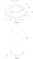
- the infused object container includes a body 1, a baffle 10, a closing mechanism 20, and a connecting mechanism 30.
- the body 1 is provided with a liquid injection port 4 through up-and-down.
- the body 1 has a shape of annular-plate, but in other embodiments, it may have any other shapes such as a rectangular shape, a frame shape, a rod shape, etc., and may have various three-dimensional shapes such as a plate shape, a block shape, etc.
- the baffle 10 is movably disposed below the liquid injection port 4.
- the baffle may be disposed inside the liquid injection port 4.
- the baffle 10 can be opened by gravity and impact force of the liquid such as water in the liquid injection port 4, so that the liquid injection port 4 is unobstructed.
- the closing mechanism 20 has functions of sensing and driving or the like, when no liquid is injected, the baffle 10 is closed, and the closing mechanism 20 applies driving force to the baffle 10 to enable the baffle 10 to close the liquid injection port 4; when the liquid is injected, the closing mechanism 20 senses gravity, impact force or the like from the liquid, and when the force is larger than the driving force, the baffle 10 is opened.
- the connecting mechanism 30 is provided on the body 1 to connect with the infused object receiving member 2.
- the embodiments of the present application involve an appliance for infusing tea with water: a pot cover disposed on a pot.
- the body 1 When adding water to the appliance, the body 1 may be directly placed below water flow, after the water flow contacts the baffle 10, by means of gravity of the water, the baffle 10 overcomes the driving force applied by the closing mechanism 20, so that the liquid injection port 4 is opened, and the water can be added through the liquid injection port 4 without opening the pot cover or taking it off.
- the connecting mechanism 30 can be slidably connected with the infused object receiving member 2, so that the body 1 and the infused object receiving member 2 are connected together as a whole conveniently, the infused object receiving member 2 can be taken out synchronously when taking off the pot cover, and when the teapot is inclined the infused object receiving member 2 can be secured by the body 1, so that inclination and swinging will not occur, thereby the convenience in use is improved and the usage experience is optimized.
- the infused object receiving member 2 is required to accommodate tea leaves and extract tea ingredients therefrom, the infused object receiving member 2 is provided with a hollow cavity to accommodate infused object (such as tea) and has an opening. This opening is communicated with the liquid injection port 4 after being connected with the connecting mechanism 30, and the infused object receiving member 2 is provided with a leak hole (not shown) communicating with the hollow cavity.
- infused object such as tea
- the liquid injection port 4 which is a vertical through-hole, provided on the body 1, may be cylindrical, semi-cylindrical in shape, or may have a conical shape with a large top and a small bottom, or may have other shapes allowing water flow to pass through, which is not limited in the present application.
- the baffle 10 may be hinged to the body 1 by means of a rotating shaft, and the closing mechanism 20 may be a return spring disposed between the body 1 and the baffle 10, and the return spring applies from downward an elastic driving force to the tail of the baffle 10, so that the baffle 10 may rotate upward around the rotating shaft and covers the lower part of the liquid injection port 4.
- the closing mechanism may also be a counterweight at the other side of the rotating shaft, while the counterweight and the baffle are respectively located at both sides of the rotating shaft to form a seesaw-like movement mode.
- the baffle 10 may also be provided below the liquid injection port 4 slidably in an up-and-down direction by a mechanism such as a slide, and the closing mechanism is a return spring that is provided below the baffle 10 and drives the baffle 10 to move up-and-down.
- the connecting mechanism 30 is disposed at the lower bottom surface of the body 1 and is slidably connected with the infused object receiving member 2, the sliding direction is parallel to the lower bottom surface of the body 1, so that the infused object receiving member 2 can be simply connected onto the lower bottom surface of the body 1 through a sliding translational movement.
- the connecting mechanism 30 may also be disposed at the side of the body 1 and slidably connected with the infused object receiving member 2. In use, the body 1 is placed on the pot body, and the infused object receiving member 2 is located inside the pot body.
- the connecting mechanism 30 comprises a support part 31, the top of the infused object receiving member 2 has a first protrusion 3, and the support part 31 is used to support the first protrusion 3 so that the infused object receiving member 2 may be secured and sliding-fitted with the connecting mechanism 30.
- the top of the infused object receiving member 2 may have a flanging to form the first protrusion 3, and the support part 31 has a clasp extending toward the inside of the pot cover such that the flanging is slip-fitted with the clasp such that the infused object receiving member 2 is slidably connected with the pot cover; or a top plate extending away from the infused object receiving member 2 is formed to constitute the first protrusion 3, and the support part 31 has a slide extending toward the inside the pot cover such that the top plate is slip-fitted with the slide to slidably connect the infused object receiving member 2 with the pot cover.
- the connecting mechanism 30 further includes a limiting block 32, the limiting block 32 is disposed behind the support part 31 in the sliding direction, and when the limiting block 32 contacts with the first protrusion 3, the limiting block 32 blocks the sliding of the first protrusion 3 towards the limiting block 32.
- the limiting block 32 can limit the infused object receiving member 2 such that the infused object receiving member 2 stops after sliding to the mounting position.
- the sliding direction is a direction from left to right in the drawing.
- the limiting block 32 is disposed at the right of the support part 31, the first protrusion 3 can slide in, along a direction from left to right, and cooperates with the support part 31, and when the first protrusion 3 contacts the limiting block 32, the limiting block 32 blocks the first protrusion 3 from sliding continuously.
- the limiting block 32 may have a baffle extending in a direction away from the pot cover, the limiting block 32 may be in a flat plate shape, a step shape or any other shape having a curved surface, and the limiting block 32 may be provided only one at an end point of the sliding direction, or may be provided in pairs, which is not particularly limited in the present application.
- the connecting mechanism 30 further includes a connecting portion 33, the connecting portion 33 is connected to the lower bottom surface of the body 1.
- the support part 31 is disposed outside of the connecting portion 33, the support part 31 is L-shaped and has an opening towards the connecting portion 33, and a mounting groove is formed between the support part 31 and the connecting portion 33.
- the mounting groove has a height which is greater than or equal to the height of the first protrusion 3, so that the first protrusion 3 slides within the mounting groove.
- the connecting portion 33 and the support part 31 form the mounting groove such that a space of movement up-and-down is limited when the infused object receiving member 2 is in slip connection with the pot cover, so that it is convenient for mounting the infused object receiving member 2, and that the infused object receiving member 2 is more stable with a reduced sway after connecting with the pot cover.
- the connecting portion 33 may be semi-circular, annular or square.
- the support part is L-shaped, and one side of the support part extends towards the connecting portion 33 and is lower than the connecting portion 33 so as to form a mounting groove with the connecting portion 33.
- the connecting portion 33 is annular
- the first protrusion 3 is also annular
- the support part 31 is provided in pairs in a diameter direction of the connecting portion 33, so that they are able to support the infused object receiving member 2 more stably.
- the mounting groove has a height which is equal to the height of the first protrusion 3, when the infused object receiving member 2 is connected with the connecting mechanism 30, the connecting portion 33 contacts the first protrusion 3 to limit an up-and-down movement of the first protrusion 3 within the mounting groove, so that the infused object receiving member 2 can be mounted more stably and, it can be more steady after connection. Meanwhile, after contacting with the first protrusion 3, the connecting portion 33 may close the opening of the infused object receiving member 2 to a certain extent to avoid the contents (such as tea leaves, etc.) in the infused object receiving member 2 from leaking out, or to avoid other foreign matters from entering the infused object receiving member 2.
- the connecting mechanism 30 further includes a locking pin 34
- the locking pin 34 includes a curved surface towards the circle center of the connecting portion 33
- the locking pins 34 are provided in pairs and are respectively disposed adjacent to the two support parts 31, and the minimum distance between the two curved surfaces of the two locking pins 34 is smaller than the diameter of the outer rim or periphery of the first protrusion 3 so that the sliding of the first protrusion 3 is limited.
- the locking pin 34 may have a cylindrical shape, a semi-cylindrical shape, or a U-shaped cylindrical shape, or other shape with a circular surface, while the present application is not limited thereto.
- the connecting mechanism 30 further includes a guide plate 35, the guide plate 35 is disposed outside of the connecting portion 33, and an extending direction of the guide plate 35 coincides with a sliding direction of infused object receiving member 2.
- the guide plate 35 can guide the slip-fit of the first protrusion 3 and the connecting mechanism 30, so that the infused object receiving member 2 and the body 1 can be connected and detached more conveniently.
- the guide plates 35 are provided in pairs in a diameter direction of the connecting portion 33, so that a guiding function of the guide plate 35 is enhanced, and a possible damage caused by connecting or disassembling in an improper direction is avoided.
- the support parts 31 are provided in a pair mirror-symmetrically in a diameter direction of the connecting portion 33, the locking pins 34 are provided in a pair in the direction that the support parts 31 are far away from the limiting blocks 32 and are respectively adjacent to the two support parts 31, the guide plate 35 is provided in a pair at the other side of the locking pins 34, and the support parts 31, the locking pins 34 and the guide plate 35 are all disposed outside of the connecting portion 33, so that the connecting mechanism 30 is simple and compact in structure with a good connection performance, and is convenient for connection and disassembly of the infused object receiving member 2 and the pot cover.
- the pot cover further comprises a handling portion 40 which is provided on the body 1 to facilitate the operation of the body 1 and the embodiment.
- the handling portion 40 is an obliquely extending handle which is provided above the body 1.
- the handling portion may also be a recess into which a finger or other tools can be inserted to lift the body 1 or the like.
- the teapot of this embodiment may include the above pot cover and pot body, in which:
- the pot body may accommodate liquid such as water, milk or the like.
- the pot cover may be directly buckled at the top of the pot body, and may be taken off to separate the pot cover and the pot body; the pot cover may also be hinged on the top of the pot body, so that the pot cover can rotate upwards to open the pot cover.
- the teapot can be an electric pot, but is not limited thereto.
- the teapot may be directly placed below water flow when adding water thereto, after water flow contacts the baffle 10 of the pot cover, the baffle 10 opens the liquid injection port 4, which makes it possible to add water into the pot body without taking off or opening the pot cover, and thus the teapot is both simple and reliable in structure.
- the teapot provided by the present application may comprise the pot cover, the pot body and the infused object receiving member 2, where the pot cover and the pot body have been described in detail above, and the infused object receiving member 2 may be connected with the pot cover.
- the teapot of the present disclosure may also connect with infused object receiving member 2 such that when making tea in the teapot, water directly flows into the infused object receiving member 2 from the liquid injection port 4 through the baffle 10 of the pot cover to brew tea leaves, that is, the advantage of making tea without taking off or opening the pot cover is realized.
- the teapot of the present application when it is desired to add tea leaves to the infused object receiving member 2, a pressure may be exerted directly to the baffle 10 to push tea leaves into the infused object receiving member 2; and, when taking out or changing tea leaves, the infused object receiving member 2 may be taken out synchronously when taking off the pot cover, so that the operation of making tea can be simplified and more convenient.
- the infused object receiving member 2 is connected to the pot cover, so that when the teapot is tilted (for example, when pouring tea), the pot cover can provides a fixation to the infused object receiving member 2, so that the infused object receiving member 2 is prevented from tilt and swing, and thus the usage experience is optimized.
- the infused object receiving member 2 is detachably connected with the pot cover so that the infused object receiving member 2 in the teapot can be taken out when it is not in use or it needs to be brought out to change tea leaves, thereby improves the detachability and use convenience of the teapot.
- the present application may also use other liquids to impact, infuse or brew, or excite the contents in the infused object receiving member 2, for example, to infuse and extract coffee, traditional Chinese medicines, or the like in the infused object receiving member 2 by using various of drinking water (including hot or cold water), alcohol, etc.,.
- This embodiment can also be applied to kitchen cooking or the like by using special materials such as glass, stainless steel or the like. For example, by placing spices in the infused object receiving member 2, into which the high temperature cooking oil is injected, the cooking oil can activate an aroma of the spices and then flow out of the infused object receiving member, while leaving the residue of the spices in the infused object receiving member.
- the present application can obtain great breakthrough in use, for example, to form it as an independent commodity, place tea leaves in the infused object receiving member 2 and then it can be independently packaged and sold.
- the shape of the body 1 may be arbitrarily selected according to requirements, for example, the body can be in a relatively long rod shape with two ends supported on two side walls of a larger tank, which can bring great convenience in a crowded public places.
- the connecting mechanism includes a slide 1000 and a point-like bulge 1020 which are respectively provided below the body 101 and extend obliquely along a circumferential direction.
- the connecting mechanism includes a cylindrical connecting portion 1033 disposed below the body 101, the slide 1000 is a long strip provided at the connecting portion 1033 and protrudes outwards, and the point-like bulge 1020 is provided at the inner wall of the opening of the infused object receiving member 102.
- the slide 1000 may be a correspondingly shaped recess or through hole, and the positions of the slide 1000 and the point-like bulge 1020 can be interchanged.
- the direction of operation is indicated by the arrow in FIG. 11 , the infused object receiving member 102 is moved along the translation arrow to approach the connecting portion 1033 and that the point-like bulge 1020 is placed above the slide 1000, and then rotated along the arc arrow so that the infused object receiving member 102 can be connected to the body 101.
- a reverse operation can be performed.
- the connecting mechanism comprises an elastic bulge 200 located below the body 201, and the elastic bulge 200 connects the body 201 to the infused object receiving member 202 in an abutting manner.
- the connecting mechanism includes a cylindrical connecting portion 2033 disposed below the body 201, the elastic bulge 200 is provided at the connecting portion 2033, and the opening of the infused object receiving member 202 is fitted over on the connecting portion 2033 and enables the elastic bulge 200 to abut against the opening.
- the elastic bulge may also be provided at the infused object receiving member.
- the elastic bulge 200 and the connecting portion 2033 are formed as an integrated configuration, and in order to form such configuration, a sidewall of the connecting portion 2033 with a thin-wall structure may be hollowed out, and a region surrounded by the hollow-out part is inclined toward the outside the sidewall of the connecting portion 2033 so as to form the elastic bulge 200.
- the material of the connecting portion 2033 should have certain flexibility, for example, the material should be stainless steel, plastic material, but should not be glass or the like.
- the infused object receiving member 202 When applied, as shown in FIG. 13 , the infused object receiving member 202 is moved along the arrow direction so that its opening fits or is inserted into the connecting portion 2033 and the elastic bulges 200 abut against the side wall of the infused object receiving member 202, thereby connecting the body 201 with the infused object receiving member 202. When they need to be separated, one just need to pull them along the opposite direction of the arrow.
Landscapes
- Engineering & Computer Science (AREA)
- Food Science & Technology (AREA)
- Table Devices Or Equipment (AREA)
- Coating Apparatus (AREA)
- Apparatus For Making Beverages (AREA)
- Medical Preparation Storing Or Oral Administration Devices (AREA)
- Infusion, Injection, And Reservoir Apparatuses (AREA)
Applications Claiming Priority (2)
| Application Number | Priority Date | Filing Date | Title |
|---|---|---|---|
| CN202221920930.5U CN218127945U (zh) | 2022-07-21 | 2022-07-21 | 壶盖及茶壶 |
| PCT/CN2023/108192 WO2023227142A1 (zh) | 2022-07-21 | 2023-07-19 | 泡制物容器及泡制装置 |
Publications (2)
| Publication Number | Publication Date |
|---|---|
| EP4400007A1 true EP4400007A1 (de) | 2024-07-17 |
| EP4400007A4 EP4400007A4 (de) | 2025-05-14 |
Family
ID=84595547
Family Applications (1)
| Application Number | Title | Priority Date | Filing Date |
|---|---|---|---|
| EP23811212.2A Pending EP4400007A4 (de) | 2022-07-21 | 2023-07-19 | Aufgussobjektbehälter und aufgussvorrichtung |
Country Status (6)
| Country | Link |
|---|---|
| EP (1) | EP4400007A4 (de) |
| CN (1) | CN218127945U (de) |
| IL (1) | IL310904A (de) |
| TR (1) | TR2024002547U5 (de) |
| WO (1) | WO2023227142A1 (de) |
| ZA (1) | ZA202501189B (de) |
Families Citing this family (1)
| Publication number | Priority date | Publication date | Assignee | Title |
|---|---|---|---|---|
| CN218127945U (zh) * | 2022-07-21 | 2022-12-27 | 宁波西摩电器有限公司 | 壶盖及茶壶 |
Family Cites Families (10)
| Publication number | Priority date | Publication date | Assignee | Title |
|---|---|---|---|---|
| US5775205A (en) * | 1996-12-16 | 1998-07-07 | Melton; Bruce W. | Infuser unit for beverages |
| DE29906743U1 (de) * | 1999-04-15 | 2000-08-24 | Riensch & Held (GmbH & Co), 21035 Hamburg | Filtereinsatz zur Zubereitung von Teegetränken |
| GB2457074B (en) * | 2008-02-01 | 2012-02-22 | David Richard Birch | Tea pot and a tea pot having a tea filter |
| CN204133016U (zh) | 2014-10-27 | 2015-02-04 | 宁波小智电器科技有限公司 | 水壶及其泡茶器 |
| CN208081034U (zh) * | 2017-05-31 | 2018-11-13 | 宁波科程电器制造有限公司 | 一种电茶壶及用于电茶壶的底座加热装置 |
| CN210810518U (zh) * | 2017-09-13 | 2020-06-23 | 浙江小智电器科技有限公司 | 水壶 |
| US11786066B2 (en) * | 2019-09-10 | 2023-10-17 | TopNet Inc. | Kettle |
| CN215604746U (zh) * | 2021-07-09 | 2022-01-25 | 景德镇敦善堂陶瓷文化传播有限公司 | 一种具有茶杯携带功能的陶瓷茶壶 |
| CN217592479U (zh) * | 2022-06-27 | 2022-10-18 | 宁波西摩电器有限公司 | 茶壶 |
| CN218127945U (zh) * | 2022-07-21 | 2022-12-27 | 宁波西摩电器有限公司 | 壶盖及茶壶 |
-
2022
- 2022-07-21 CN CN202221920930.5U patent/CN218127945U/zh active Active
-
2023
- 2023-07-19 EP EP23811212.2A patent/EP4400007A4/de active Pending
- 2023-07-19 TR TR2024/002547U patent/TR2024002547U5/tr unknown
- 2023-07-19 IL IL310904A patent/IL310904A/en unknown
- 2023-07-19 WO PCT/CN2023/108192 patent/WO2023227142A1/zh not_active Ceased
-
2025
- 2025-02-07 ZA ZA2025/01189A patent/ZA202501189B/en unknown
Also Published As
| Publication number | Publication date |
|---|---|
| CN218127945U (zh) | 2022-12-27 |
| EP4400007A4 (de) | 2025-05-14 |
| IL310904A (en) | 2024-04-01 |
| WO2023227142A1 (zh) | 2023-11-30 |
| ZA202501189B (en) | 2025-08-27 |
| TR2024002547U5 (tr) | 2024-03-21 |
Similar Documents
| Publication | Publication Date | Title |
|---|---|---|
| JP5373977B2 (ja) | 閉鎖可能な注ぎ開口部を備えたティー・メーカー | |
| CN103442625B (zh) | 容器封闭物 | |
| EP2866625B1 (de) | Gerät zur zubereitung von lebensmitteln | |
| AU2004281150A1 (en) | Beverage mixer and heater | |
| WO2010107867A2 (en) | Tea and herb infusing beverage container | |
| US5063837A (en) | Beverage brewing apparatus with drip preventing mechanism | |
| JP2020511204A (ja) | 飲料を混合して飲むための容器 | |
| CN101237798B (zh) | 泡制装置的闭合机构 | |
| WO2023227142A1 (zh) | 泡制物容器及泡制装置 | |
| CN107529907A (zh) | 饮料分配机器 | |
| EP2455326A1 (de) | Verbesserte tragbare getränkeausgabevorrichtung zur verwendung für gruppen | |
| RU236997U1 (ru) | Контейнер для настаиваемого вещества | |
| CN219556604U (zh) | 随行杯 | |
| KR20090051216A (ko) | 베이어넷 연결을 통해 추출실 상단부에 연결될 수 있는 패드 홀더를 구비한 음료 제조장치 | |
| CN112040819B (zh) | 用于饮料机的穿刺机构 | |
| CN209404476U (zh) | 多种饮品冲泡机 | |
| CN201727242U (zh) | 一种新型手动出液壶 | |
| CN213757775U (zh) | 过滤纸杯及咖啡机 | |
| CN113925348B (zh) | 一种带有抽拉式冲泡装置的胶囊咖啡机 | |
| CN210631087U (zh) | 出水控制装置及饮品冲泡容器 | |
| CN218552025U (zh) | 一种饮品固液分离装置以及冲泡装置 | |
| CN209574240U (zh) | 分离式水杯 | |
| CN208925730U (zh) | 一种防误碰漏水水杯 | |
| US2258589A (en) | Coffee maker | |
| JP3551902B2 (ja) | 真空保温容器による飲料抽出・保温方法と飲料抽出・保温器 |
Legal Events
| Date | Code | Title | Description |
|---|---|---|---|
| STAA | Information on the status of an ep patent application or granted ep patent |
Free format text: STATUS: THE INTERNATIONAL PUBLICATION HAS BEEN MADE |
|
| PUAI | Public reference made under article 153(3) epc to a published international application that has entered the european phase |
Free format text: ORIGINAL CODE: 0009012 |
|
| STAA | Information on the status of an ep patent application or granted ep patent |
Free format text: STATUS: REQUEST FOR EXAMINATION WAS MADE |
|
| 17P | Request for examination filed |
Effective date: 20240208 |
|
| AK | Designated contracting states |
Kind code of ref document: A1 Designated state(s): AL AT BE BG CH CY CZ DE DK EE ES FI FR GB GR HR HU IE IS IT LI LT LU LV MC ME MK MT NL NO PL PT RO RS SE SI SK SM TR |
|
| A4 | Supplementary search report drawn up and despatched |
Effective date: 20250410 |
|
| RIC1 | Information provided on ipc code assigned before grant |
Ipc: A47J 27/21 20060101ALI20250404BHEP Ipc: A47J 31/44 20060101ALI20250404BHEP Ipc: A47J 31/20 20060101ALI20250404BHEP Ipc: A47J 31/06 20060101ALI20250404BHEP Ipc: A47G 19/14 20060101AFI20250404BHEP |
|
| DAV | Request for validation of the european patent (deleted) | ||
| DAX | Request for extension of the european patent (deleted) |