EP4398618A2 - Verfahren zur bereitstellung von ankerwechsel für ethernet-pou-sitzungen und zugehörige netzwerkeinheiten/-knoten - Google Patents
Verfahren zur bereitstellung von ankerwechsel für ethernet-pou-sitzungen und zugehörige netzwerkeinheiten/-knoten Download PDFInfo
- Publication number
- EP4398618A2 EP4398618A2 EP24177028.8A EP24177028A EP4398618A2 EP 4398618 A2 EP4398618 A2 EP 4398618A2 EP 24177028 A EP24177028 A EP 24177028A EP 4398618 A2 EP4398618 A2 EP 4398618A2
- Authority
- EP
- European Patent Office
- Prior art keywords
- entity
- ethernet
- upf
- wireless terminal
- base station
- Prior art date
- Legal status (The legal status is an assumption and is not a legal conclusion. Google has not performed a legal analysis and makes no representation as to the accuracy of the status listed.)
- Withdrawn
Links
Images


Classifications
-
- H—ELECTRICITY
- H04—ELECTRIC COMMUNICATION TECHNIQUE
- H04L—TRANSMISSION OF DIGITAL INFORMATION, e.g. TELEGRAPHIC COMMUNICATION
- H04L12/00—Data switching networks
- H04L12/28—Data switching networks characterised by path configuration, e.g. LAN [Local Area Networks] or WAN [Wide Area Networks]
- H04L12/44—Star or tree networks
-
- H—ELECTRICITY
- H04—ELECTRIC COMMUNICATION TECHNIQUE
- H04W—WIRELESS COMMUNICATION NETWORKS
- H04W36/00—Hand-off or reselection arrangements
- H04W36/0005—Control or signalling for completing the hand-off
- H04W36/0011—Control or signalling for completing the hand-off for data sessions of end-to-end connection
- H04W36/0033—Control or signalling for completing the hand-off for data sessions of end-to-end connection with transfer of context information
-
- H—ELECTRICITY
- H04—ELECTRIC COMMUNICATION TECHNIQUE
- H04W—WIRELESS COMMUNICATION NETWORKS
- H04W36/00—Hand-off or reselection arrangements
- H04W36/0005—Control or signalling for completing the hand-off
- H04W36/0055—Transmission or use of information for re-establishing the radio link
- H04W36/0069—Transmission or use of information for re-establishing the radio link in case of dual connectivity, e.g. decoupled uplink/downlink
- H04W36/00695—Transmission or use of information for re-establishing the radio link in case of dual connectivity, e.g. decoupled uplink/downlink using split of the control plane or user plane
-
- H—ELECTRICITY
- H04—ELECTRIC COMMUNICATION TECHNIQUE
- H04W—WIRELESS COMMUNICATION NETWORKS
- H04W36/00—Hand-off or reselection arrangements
- H04W36/12—Reselecting a serving backbone network switching or routing node
Definitions
- the present disclosure relates generally to communications, and more particularly to wireless communications and related communication entities and/or nodes.
- the 5G system has defined a number of Session and Service Continuity (SSC) modes for wireless terminals (UEs) that move. These modes may facilitate the use of a PDU Session Anchor (PSA) that is close to the UE's current point of attachment to the network in RAN.
- SSC modes 1, 2 and 3 are defined in 3GPP TS 23.501 section 5.6.9.
- the currently defined SSC modes are as follows.
- SSC modes 2 and 3 may apply to only PDU Session types IPv4/v6, while SSC mode 1 can apply to any type of PDU Session. The reason is that SSC modes 2 and 3 may imply that the UE will get a new IP address assigned for its new PDU session. A new IP address may be necessary, because the IP address may carry topological significance at the data network, hence a PSA at a new location may require an IP address in the case of IP routing.
- Existing solutions may not adequately address mobility issues relating to Ethernet PDU sessions.
- 3GPP TS 23.501 V15.2.0 discloses handling of Ethernet PDU sessions between an SMF and a UPF, wherein an SMF can configure an UPF acting as PSA for an Ethernet PDU session and instruct the UPF to route downlink traffic based on the MAC address used by the UE for the uplink traffic.
- 3GPP TR 23.725 V0.2.0 discloses a handover scenario for a UE, wherein SMF selects a new target UPF for the PDU session.
- the invention provides methods, devices and systems according to the independent claims. Further embodiments are provided by the dependent claims.
- complexity in handling Ethernet PDU sessions may be reduced in both the network and in the user equipment, and a need for PDU session release and re-establishment may be reduced/avoided.
- shorter delays may be provided by using a nearby PSA without impacting operations of user equipment.
- Mobile terminal UE may also include a processor circuit 703 (also referred to as a processor) coupled to the transceiver circuit, and a memory circuit 705 (also referred to as memory) coupled to the processor circuit.
- the memory circuit 705 may include computer readable program code that when executed by the processor circuit 703 causes the processor circuit to perform operations according to embodiments disclosed herein. According to other embodiments, processor circuit 703 may be defined to include memory so that a separate memory circuit is not required.
- Mobile terminal UE may also include an interface (such as a user interface) coupled with processor 703, and/or mobile terminal UE may be incorporated in a vehicle.
- operations of the NodeB base station may be performed by processor 803, network interface 807, and/or transceiver 801.
- processor 803 may control transceiver 801 to transmit communications through transceiver 801 over a radio interface to one or more mobile terminals UEs and/or to receive communications through transceiver 801 from one or more mobile terminals UEs over a radio interface.
- processor 803 may control network interface 807 to transmit communications through network interface 807 to one or more other network nodes/entities and/or to receive communications through network interface from one or more other network nodes/entities.
- modules may be stored in memory 805, and these modules may provide instructions so that when instructions of a module are executed by processor 803, processor 803 performs respective operations.
- the network entity may also include a processor circuit 903 (also referred to as a processor) coupled to the network interface circuit 907, and a memory circuit 905 (also referred to as memory) coupled to the processor circuit.
- the memory circuit 905 may include computer readable program code that when executed by the processor circuit 903 causes the processor circuit to perform operations according to embodiments disclosed herein. According to other embodiments, processor circuit 903 may be defined to include memory so that a separate memory circuit is not required.
- operations of the network entity may be performed by processor 903 and/or network interface 907.
- processor 903 may control network interface 907 to transmit communications through network interface 907 to one or more other network nodes/entities and/or to receive communications through network interface from one or more other network nodes/entities.
- modules may be stored in memory 905, and these modules may provide instructions so that when instructions of a module are executed by processor 903, processor 903 performs respective operations.
- the structure of the network entity of Figure 7 may be used, for example, to implement a UPF entity, an AMF entity, and/or an SMF entity to perform operations thereof as discussed in greater detail below.
- Operations of a network entity of Figure 7 for example, may be performed by one network server or distributed across a plurality of network servers having the structure of Figure 7 , and a plurality of such distributed servers may be collectively referred to as a server.
- Embodiments of Figure 1 may be applied in a 5G system, but the same/similar embodiments may be equally applied, with appropriate adjustments, in a 4G system, a 3G system, a 2G system, and/or other mobile/wireless communication systems.
- wireless terminal UE is originally connected via RAN node Source gNB (also referred to as a source base station) and CN node Source UPF, acting as the PSA.
- the CN control plane entities AMF, SMF may assist in establishment of the session.
- Figure 1 also shows the control plane entities UDM, NRF, PCF, NEF, even though they may not be essential to the discussion below.
- the 5G system connects to an Ethernet data network, shown as ETH subnet.
- the source UPF may maintain an Ethernet context (ETH cntxt), which includes information related to the Ethernet network that it connects to. More particularly, the Ethernet context includes the MAC address used by the wireless terminal UE for Ethernet traffic.
- the Medium Access Control MAC address may be determined by the UPF, for example, by learning the Medium Access Control MAC address based on the ongoing traffic, or by explicit configuration. In some cases, there may be multiple MAC addresses corresponding to the PDU session, due to the wireless terminal UE having multiple addresses, or due to other Ethernet devices connecting via the UE (in which case the Ethernet context may include multiple MAC addresses).
- wireless terminal UE moves to a target gNB (also referred to as a target base station).
- the CN or more particularly the SMF, may decide to establish a new PSA.
- the Target UPF will act as the new PSA.
- the tunneling is updated, from the Source gNB - Source UPF tunnel before the handover to the Target gNB - Target UPF after the handover.
- the SMF installs the Ethernet context in the Target UPF. After that, the target UPF updates the forwarding in the Ethernet subnetwork. This may be done in several ways, depending on which mode of operation is used.
- the operations discussed above may be repeated for all MAC addresses of the Ethernet context for the UE.
- the Ethernet handling functions are not integrated with the UPF, in which case the UPF may instruct the Ethernet handling functions to perform the necessary operations, using a signaling protocol.
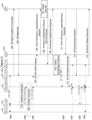
- the signaling diagram of Figure 2 illustrates some embodiments of inventive concepts for an Xn based handover in a 5G system from the Source gNB 253 to the Target gNB 255.
- the Xn based handover may be updated.
- Ethernet PDU Session is established with the user data going via Source gNB 253 and Source UPF 257 (at 200a).
- the Source UPF 257 acts as the PSA.
- the End marker (at 200f), sent after operation 213, may be optional according to some embodiments, and that the End marker may be omitted according to some embodiments.
- the Target gNB 255 may not reorder the downlink frames, or alternatively, the Target gNB 255 may wait for a timeout period of time while it only sends forwarded frames to the UE 251, and after the timeout it stops sending forwarded frames and only delivers downlink frames from the Target UPF 259.
- Whether or not to use the End marker can be established based on configuration, which should be consistent in the system for a given UE whether or not End markers are expected to be used.
- the end marker may thus be omitted/skipped in case of UPF change.
- the RAN node e.g., target gNB 255
- the RAN node may be made aware that it should not expect the end marker packets to arrive in case of UPF change for Ethernet PDU sessions.
- the RAN node may be configured to not expect the end marker in case of a given combination of slice identifiers and PDU types.
- whether or not the RAN node should expect the end marker may be indicated individually at each change of the UPF together with the signaling that updates the N3 tunnel endpoint at the UPF. This may occur during the handover procedure, even though UPF change without handover could also be possible. Examples of UPF change with and without handover are illustrated in Figure 6.11.2-1 of 3GPP TR 23.725 v2.0.0 (2018-12) section 6.11 (cited below).
- operations 9 and 10 in case of handover, and (optionally) operation 11 in case of no handover may include an additional flag which indicates to the RAN node whether or not it should expect the end marker when the UPF endpoint of the N3 tunnel is changed.
- a no end marker flag may be included in the messages of operations 211 and 212.
- the RAN node may decide to wait for a short period of time for the end marker and buffer new downlink packets coming from the UPF directly. I.e., in cases of uncertainty regarding the end marker, the threshold period of time to wait for the end marker may be reduced/lowered so that the RAN node avoids waiting too long for an end marker that never arrives. It may also be possible to not wait at all for the end marker in cases of uncertainty and deliver all downlink packets as they arrive without reordering.
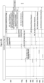
- Figures 3A-B and 4A-B illustrate embodiments of inventive concepts in dual connectivity DC settings where a Dual Connectivity feature is used in the RAN, and a single UE 351 connects to both a MgNB 353 (Master gNB) and a SgNB 355 (Secondary gNB).
- International App. No. PCT/IB2017/058517 describes situations where the UE maintains two PDU Sessions in parallel for redundancy both in the RAN and in the CN.
- FIG. 3A and 3B illustrates some embodiments applied to dual connectivity where a new Secondary gNB 355 is added.
- the UE 351 originally has two PDU Sessions, a first PDU session via MgNB 353 and UPF1 357 at 300a, and a second PDU session via MgNB 353 and UPF2A (referred to as secondary source UPF 359) at 300b.
- the second PDU session may be handed over from MgNB 353 and secondary source UPF 359 to SgNB 355 and secondary target UPF 361 (UPF2B).
- Operations of secondary source UPF 359 may be similar to operations discussed above with respect to source UPF 257
- operations of secondary target UPF 361 may be similar to operations discussed above with respect to target UPF 259.
- operations 306-313 and 316-317 may be similar to operations 205-214.
- operations 314 and 315 from the diagram of Figures 3A-B however, the uplink tunnel endpoint at the new PDU Session Anchor UPF2 (secondary target UPF 361) is sent from the MgNB 353 to the SgNB 355, as SgNB 355 is the node terminating the tunnel.
- the signaling diagram of Figures 4A and 4B illustrates some embodiments applied to combined dual connectivity handover where the MgNB and SgNB are both changed (and the case that the SgNB does not change can be regarded as a special case of this scenario).
- the handover itself with dual connectivity may be performed according to 3GPP TS 37.340 section 10.7.2.
- a first PDU session is set up via source MgNB 453 and source primary UPF 461 (at 400a)
- a second PDU session is set up via source SgNB 455 and source secondary UPF 465 (at 400b), in line with international application number PCT/IB2017/058517.
- Embodiments of the present disclosure may be performed accordingly for both first and second PDU Sessions, as discussed below with respect to Figures 4A and 4B .
- an Ethernet PDU session may change its PDU Session Anchor (PSA) such that:
- PSA PDU Session Anchor
- SMF entity also referred to as an SMF node/server
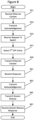
- SMF entity 263 of Figure 2 Operations of session management function SMF entity (also referred to as an SMF node/server) of a wireless communication network (e.g., SMF entity 263 of Figure 2 ) will now be discussed with reference to the flow chart of Figure 8 .
- the SMF entity may be implemented using the structure of Figure 7 with modules stored in memory 905 so that the modules provide instructions so that when the instructions of a module are executed by processor 903, processor 903 performs respective operations.
- Processor 903 of the SMF entity may thus transmit and/or receive communications to/from one or more other network nodes/entities/servers of a wireless communication network through network interface 907.
- processor 903 may receive an N4 report including an Ethernet context for a wireless terminal UE (e.g., wireless terminal 251 of Figure 2 ) from a first user plane function UPF entity (e.g., source UPF entity 257 of Figure 2 ) through network interface 907.
- the Ethernet context may be provided for an Ethernet Protocol Data Unit PDU Session for the wireless terminal using the first UPF entity, and the Ethernet context may include a Medium Access Control MAC address for the wireless terminal UE.
- Operations of block 851 may be performed as discussed above, for example, with respect to operation 201 of Figure 2 , operation 301 of Figure 3A , operation 401 of Figure 4A , and/or operation 403 of Figure 4A .
- processor 903 may receive a request to switch the Ethernet PDU session for the wireless terminal from an AMF entity (e.g., AMF entity 261 of Figure 2 ) through network interface 907.
- AMF entity e.g., AMF entity 261 of Figure 2
- Operations of block 855 may be performed as discussed above, for example, with respect to operation 206 of Figure 2 , operation 307 of Figure 3A , operation 414 of Figure 4A , and/or operation 420 of Figure 4B .
- processor 903 may select a second UPF entity (e.g., target UPF entity 259 of Figure 2 ) responsive to receiving the request to switch the Ethernet PDU session for the wireless terminal.
- Operations of block 857 may be performed as discussed above, for example, with respect to operation 207 of Figure 2 , operation 308 of Figure 3A , operation 415 of Figure 4A , and/or operation 421 of Figure 4B .
- processor 903 may transmit an N4 session establishment request including the Ethernet context including the MAC address for the wireless terminal through network interface 907 to the second UPF entity.
- processor 903 may receive an N4 session establishment response through network interface 907. Operations of block 861 may be performed as discussed above, for example, with respect to operation 209 of Figure 2 , operation 310 of Figure 3B , operation 417 of Figure 4B , and/or operation 423 of Figure 4B .
- processor 903 may transmit an acknowledgement of the request to switch through network interface 907 to the AMF entity after selecting the second UPF entity, and the acknowledgment may include an identification of the second UPF entity.
- Operations of block 863 may be performed as discussed above, for example, with respect to operation 211 of Figure 2 , operation 312 of Figure 3B , and/or operation 425 of Figure 4B .
- processor 903 may transmit a session release request for the wireless terminal through network interface 907 to the first UPF entity (source UPF) responsive to selecting the second UPF entity.
- Operations of block 865 may be performed as discussed above, for example, with respect to operation 213 of Figure 2 , operation 316 of Figure 3B , operation 429 of Figure 4B , and/or operation 431 of Figure 4B .
- the Ethernet context at block 851 may include a plurality of MAC addresses for the wireless terminal, and transmitting the Ethernet context at block 859 may include transmitting the Ethernet context including the plurality of MAC addresses.
- FIG. 8 Various operations of Figure 8 may be optional with respect to some embodiments of inventive concepts. For example, operations 853, 855, 857, 861, 863, 865, and/or 867 of Figure 8 may be optional with respect to Example Embodiment 1 discussed below.
- UPF entity also referred to as an UPF node/server
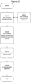
- UPF entity 259 of Figure 2 Operations of user plane function entity (also referred to as an UPF node/server) of a wireless communication network (e.g., UPF entity 259 of Figure 2 ) will now be discussed with reference to the flow chart of Figure 9 .
- the UPF entity may be implemented using the structure of Figure 7 with modules stored in memory 905 so that the modules provide instructions so that when the instructions of a module are executed by processor 903, processor 903 performs respective operations.
- Processor 903 of the UPF entity may thus transmit and/or receive communications to/from one or more other network nodes/entities/servers of a wireless communication network through network interface 907.
- processor 903 may receive a request to establish an Ethernet Protocol Data Unit PDU Session for a wireless terminal (e.g., wireless terminal UE 251 of Figure 2 ) using an Ethernet network, and the request to establish the Ethernet PDU Session may include a Medium Access Control MAC address for the wireless terminal.
- the request may be received from an SMF entity (e.g., SMF entity 263 of Figure 2 ) through network interface 907 as an N4 session establishment request.
- the request may include an Ethernet context for the wireless terminal, and the Ethernet context may include the MAC address for the wireless terminal.
- Operations of block 951 may be performed as discussed above, for example, with respect to operation 208 of Figure 2 , operation 309 of Figure 3B , operation 416 of Figure 4A , and/or operation 422 of Figure 4B .
- processor 903 may transmit an N4 session establishment response through network interface 907 to the SMF entity. Operations of block 953 may be performed as discussed above, for example, with respect to operation 209 of Figure 2 , operation 310 of Figure 3B , operation 417 of Figure 4B , and/or operation 423 of Figure 4B .
- processor 903 may update forwarding for the wireless terminal in the Ethernet network using the MAC address for the wireless terminal responsive to receiving the request.
- updating forwarding for the wireless terminal may include flooding the Ethernet network with a frame including the MAC address of the wireless terminal as a source of the frame.
- updating forwarding for the wireless terminal may include transmitting an instruction to a controller of the Ethernet network to forward downlink traffic for the wireless terminal through the UPF entity. Operations of block 955, may be performed as discussed above, for example, with respect to operation 210 of Figure 2 , operation 311 of Figure 3B , operation 418 of Figure 4B , and/or operation 424 of Figure 4B .
- processor 903 may receive an N4 report acknowledgement from the SMF entity through network interface 907. Operations of block 1057 may be performed as discussed above, for example, with respect to operation 202 of Figure 2 , operation 302 of Figure 3 , operation 402 of Figure 4A , and/or operation 404 of Figure 4A .
- a first UE QQ491 located in coverage area QQ413c is configured to wirelessly connect to, or be paged by, the corresponding base station QQ412c.
- a second UE QQ492 in coverage area QQ413a is wirelessly connectable to the corresponding base station QQ412a. While a plurality of UEs QQ491, QQ492 are illustrated in this example, the disclosed embodiments are equally applicable to a situation where a sole UE is in the coverage area or where a sole UE is connecting to the corresponding base station QQ412.
- the communication system of Figure 11 as a whole enables connectivity between the connected UEs QQ491, QQ492 and host computer QQ430.
- the connectivity may be described as an over-the-top (OTT) connection QQ450.
- Host computer QQ430 and the connected UEs QQ491, QQ492 are configured to communicate data and/or signaling via OTT connection QQ450, using access network QQ411, core network QQ414, any intermediate network QQ420 and possible further infrastructure (not shown) as intermediaries.
- OTT connection QQ450 may be transparent in the sense that the participating communication devices through which OTT connection QQ450 passes are unaware of routing of uplink and downlink communications.
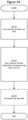
- FIG 14 is a flowchart illustrating a method implemented in a communication system, in accordance with one embodiment.
- the communication system includes a host computer, a base station and a UE which may be those described with reference to Figures 11 and 12 .
- the host computer provides user data.
- the host computer provides the user data by executing a host application.
- the host computer initiates a transmission carrying the user data to the UE.
- the transmission may pass via the base station, in accordance with the teachings of the embodiments described throughout this disclosure.
- step QQ730 (which may be optional), the UE receives the user data carried in the transmission.
Landscapes
- Engineering & Computer Science (AREA)
- Computer Networks & Wireless Communication (AREA)
- Signal Processing (AREA)
- Mobile Radio Communication Systems (AREA)
- Small-Scale Networks (AREA)
Priority Applications (1)
| Application Number | Priority Date | Filing Date | Title |
|---|---|---|---|
| EP25169539.1A EP4593463A3 (de) | 2018-06-19 | 2019-01-18 | Verfahren zur bereitstellung von ankerwechsel für ethernet-pou-sitzungen und zugehörige netzwerkeinheiten/-knoten |
Applications Claiming Priority (3)
| Application Number | Priority Date | Filing Date | Title |
|---|---|---|---|
| US201862686898P | 2018-06-19 | 2018-06-19 | |
| PCT/IB2019/050444 WO2019243901A1 (en) | 2018-06-19 | 2019-01-18 | Methods providing anchor change for ethernet pdu sessions and related network entities/nodes |
| EP19708659.8A EP3811668B1 (de) | 2018-06-19 | 2019-01-18 | Verfahren zur bereitstellung von ankerwechsel für ethernet-pdu-sitzungen und damit verbundene netzwerkeinheiten/-knoten |
Related Parent Applications (1)
| Application Number | Title | Priority Date | Filing Date |
|---|---|---|---|
| EP19708659.8A Division EP3811668B1 (de) | 2018-06-19 | 2019-01-18 | Verfahren zur bereitstellung von ankerwechsel für ethernet-pdu-sitzungen und damit verbundene netzwerkeinheiten/-knoten |
Related Child Applications (1)
| Application Number | Title | Priority Date | Filing Date |
|---|---|---|---|
| EP25169539.1A Division EP4593463A3 (de) | 2018-06-19 | 2019-01-18 | Verfahren zur bereitstellung von ankerwechsel für ethernet-pou-sitzungen und zugehörige netzwerkeinheiten/-knoten |
Publications (2)
| Publication Number | Publication Date |
|---|---|
| EP4398618A2 true EP4398618A2 (de) | 2024-07-10 |
| EP4398618A3 EP4398618A3 (de) | 2024-10-09 |
Family
ID=65635762
Family Applications (3)
| Application Number | Title | Priority Date | Filing Date |
|---|---|---|---|
| EP24177028.8A Withdrawn EP4398618A3 (de) | 2018-06-19 | 2019-01-18 | Verfahren zur bereitstellung von ankerwechsel für ethernet-pou-sitzungen und zugehörige netzwerkeinheiten/-knoten |
| EP25169539.1A Pending EP4593463A3 (de) | 2018-06-19 | 2019-01-18 | Verfahren zur bereitstellung von ankerwechsel für ethernet-pou-sitzungen und zugehörige netzwerkeinheiten/-knoten |
| EP19708659.8A Active EP3811668B1 (de) | 2018-06-19 | 2019-01-18 | Verfahren zur bereitstellung von ankerwechsel für ethernet-pdu-sitzungen und damit verbundene netzwerkeinheiten/-knoten |
Family Applications After (2)
| Application Number | Title | Priority Date | Filing Date |
|---|---|---|---|
| EP25169539.1A Pending EP4593463A3 (de) | 2018-06-19 | 2019-01-18 | Verfahren zur bereitstellung von ankerwechsel für ethernet-pou-sitzungen und zugehörige netzwerkeinheiten/-knoten |
| EP19708659.8A Active EP3811668B1 (de) | 2018-06-19 | 2019-01-18 | Verfahren zur bereitstellung von ankerwechsel für ethernet-pdu-sitzungen und damit verbundene netzwerkeinheiten/-knoten |
Country Status (6)
| Country | Link |
|---|---|
| US (3) | US11375415B2 (de) |
| EP (3) | EP4398618A3 (de) |
| JP (3) | JP7191989B2 (de) |
| CN (1) | CN112544108A (de) |
| MX (1) | MX2020013800A (de) |
| WO (1) | WO2019243901A1 (de) |
Families Citing this family (19)
| Publication number | Priority date | Publication date | Assignee | Title |
|---|---|---|---|---|
| US8658576B1 (en) | 2009-10-21 | 2014-02-25 | Encore Wire Corporation | System, composition and method of application of same for reducing the coefficient of friction and required pulling force during installation of wire or cable |
| US10056742B1 (en) | 2013-03-15 | 2018-08-21 | Encore Wire Corporation | System, method and apparatus for spray-on application of a wire pulling lubricant |
| CN110662308B (zh) * | 2018-06-30 | 2021-11-09 | 华为技术有限公司 | 一种通信方法及装置 |
| CN110830268B (zh) * | 2018-08-13 | 2022-12-30 | 华为技术有限公司 | 通信方法和通信装置 |
| WO2020034911A1 (zh) | 2018-08-13 | 2020-02-20 | 华为技术有限公司 | 通信方法和通信装置 |
| EP3858030A1 (de) * | 2018-09-27 | 2021-08-04 | Telefonaktiebolaget LM Ericsson (publ) | Dynamische und flexible konfigurationen für konfigurierte berechtigungen |
| CN111194058B (zh) * | 2018-11-14 | 2021-01-12 | 华为技术有限公司 | 下行数据的乱序控制方法及装置 |
| CN111615188B (zh) * | 2019-02-22 | 2021-10-01 | 华为技术有限公司 | 数据传输方法、装置及计算机存储介质 |
| US11470505B2 (en) * | 2019-08-30 | 2022-10-11 | Parallel Wireless, Inc. | Support for linking of packet detection rules (PDR) for optimizing throughput of combined serving gateway (SGW)/packet gateway (PGW) architecture |
| US12225417B2 (en) | 2019-10-22 | 2025-02-11 | Telefonaktiebolaget Lm Ericsson (Publ) | Coordinated change of protocol data unit session anchors |
| KR102498052B1 (ko) * | 2020-01-06 | 2023-02-09 | 삼성전자 주식회사 | 이동통신 시스템에서 분산 시간 민감 네트워킹을 지원하기 위한 방법 및 장치 |
| CN113473525B (zh) * | 2020-03-31 | 2023-11-10 | 华为技术有限公司 | 一种数据传输的方法及装置 |
| CN113613244B (zh) * | 2020-04-17 | 2024-09-24 | 华为技术有限公司 | 一种节点切换方法和装置 |
| CN114071578B (zh) * | 2020-07-30 | 2025-11-11 | 维沃移动通信有限公司 | 数据传输方法、装置、核心网设备及接入网侧设备 |
| CN116112912A (zh) * | 2021-11-09 | 2023-05-12 | 华为技术有限公司 | 一种保持会话连续性的方法及通信装置 |
| CN114158079B (zh) * | 2021-12-21 | 2023-04-18 | 中国联合网络通信集团有限公司 | 通信方法和装置、电子设备、计算机可读介质 |
| CN115696496B (zh) * | 2022-11-01 | 2025-11-25 | 深圳艾灵网络有限公司 | 数据处理方法、用户设备、协议数据单元实体及存储介质 |
| CN116192223B (zh) * | 2023-04-25 | 2023-09-22 | 阿里巴巴达摩院(杭州)科技有限公司 | 专网信息的转发方法、车辆控制方法、装置及设备 |
| JP7634757B1 (ja) | 2024-08-14 | 2025-02-21 | 株式会社インターネットイニシアティブ | 通信制御装置、および通信制御方法 |
Citations (1)
| Publication number | Priority date | Publication date | Assignee | Title |
|---|---|---|---|---|
| WO2017058517A1 (en) | 2015-09-30 | 2017-04-06 | Mastercard International Incorporated | Method and system for authentication data collection and reporting associated with an online transaction |
Family Cites Families (14)
| Publication number | Priority date | Publication date | Assignee | Title |
|---|---|---|---|---|
| EP3419351A4 (de) * | 2016-02-17 | 2019-08-14 | LG Electronics Inc. -1- | Verfahren zum senden/empfangen von positionsregistrierungsbezogenen nachrichten in einem drahtloskommunikationssystem und vorrichtung dafür |
| CN110063084B (zh) * | 2016-10-07 | 2023-08-18 | Lg电子株式会社 | 在无线通信系统中选择会话和服务连续性模式的方法 |
| US20200120570A1 (en) * | 2016-12-15 | 2020-04-16 | Lg Electronics Inc. | Method for performing handover in wireless communication system and apparatus therefor |
| CN108282832B (zh) * | 2017-01-06 | 2021-11-30 | 北京三星通信技术研究有限公司 | 无线接入网切换方法、基站和基站的通信方法 |
| US11228949B2 (en) * | 2017-01-06 | 2022-01-18 | Samsung Electronics Co., Ltd. | Intra-RAT handover for next generation system |
| US11219095B2 (en) * | 2017-01-06 | 2022-01-04 | Lg Electronics Inc. | Method and device for managing interface for supporting LTE/NR interworking in wireless communication system |
| WO2018128528A1 (ko) * | 2017-01-09 | 2018-07-12 | 엘지전자(주) | 무선 통신 시스템에서 pdu 세션 관리 방법 및 이를 위한 장치 |
| CN109155909B (zh) * | 2017-01-16 | 2021-08-10 | Lg 电子株式会社 | 无线通信系统中用于更新ue配置的方法及其装置 |
| WO2018155934A1 (ko) * | 2017-02-22 | 2018-08-30 | 엘지전자 주식회사 | 무선 통신 시스템에서 3GPP access를 통해 non-3GPP에 관련된 데이터를 수신하는 방법 및 이를 위한 장치 |
| EP3590243B1 (de) * | 2017-03-02 | 2021-10-20 | Convida Wireless, LLC | Netzwerkdienstkontinuität ohne sitzungskontinuität |
| JP7000449B2 (ja) * | 2017-03-23 | 2022-02-10 | エルジー エレクトロニクス インコーポレイティド | 無線通信システムにおける次のメッセージのために使われるベアラのタイプを指示する方法及び装置 |
| EP3585129B1 (de) * | 2017-03-27 | 2022-05-04 | LG Electronics Inc. | Verfahren und vorrichtung zur übertragung einer nachricht mit informationen eines scg-ausfalls in einem drahtloskommunikationssystem |
| WO2018212523A1 (en) * | 2017-05-13 | 2018-11-22 | Lg Electronics Inc. | Method and apparatus for handling enhanced rlm prohibit timer in wireless communication system |
| US11363664B2 (en) * | 2018-02-19 | 2022-06-14 | Lg Electronics Inc. | Method for transmitting SM signal to terminal capable of connecting to plurality of network systems |
-
2019
- 2019-01-18 JP JP2020570104A patent/JP7191989B2/ja active Active
- 2019-01-18 EP EP24177028.8A patent/EP4398618A3/de not_active Withdrawn
- 2019-01-18 MX MX2020013800A patent/MX2020013800A/es unknown
- 2019-01-18 WO PCT/IB2019/050444 patent/WO2019243901A1/en not_active Ceased
- 2019-01-18 CN CN201980054376.1A patent/CN112544108A/zh active Pending
- 2019-01-18 US US16/476,386 patent/US11375415B2/en active Active
- 2019-01-18 EP EP25169539.1A patent/EP4593463A3/de active Pending
- 2019-01-18 EP EP19708659.8A patent/EP3811668B1/de active Active
-
2022
- 2022-05-24 US US17/751,908 patent/US11889361B2/en active Active
- 2022-12-07 JP JP2022195443A patent/JP2023036640A/ja not_active Ceased
-
2023
- 2023-12-23 US US18/395,530 patent/US12568406B2/en active Active
-
2024
- 2024-06-18 JP JP2024097956A patent/JP7717908B2/ja active Active
Patent Citations (1)
| Publication number | Priority date | Publication date | Assignee | Title |
|---|---|---|---|---|
| WO2017058517A1 (en) | 2015-09-30 | 2017-04-06 | Mastercard International Incorporated | Method and system for authentication data collection and reporting associated with an online transaction |
Non-Patent Citations (6)
| Title |
|---|
| "Technical Specification Group Radio Access Network; Evolved Universal Terrestrial Radio Access (E-UTRA) and NR; Multi-connectivity; Stage 2 (Release 15", 3GPP TS 37.340 V15.1.0, March 2018 (2018-03-01) |
| "Technical Specification Group Services and System Aspects; Procedures for the 5G System; Stage 2 (Release 15", 3GPP TS 23.502 V15.1.0, March 2018 (2018-03-01) |
| 3GPP TR 23.725 V2.0.0, December 2018 (2018-12-01) |
| 3GPP TS 23.501 V15.1.0, March 2018 (2018-03-01) |
| 3GPP TS 23.725 V2.0.0, December 2018 (2018-12-01) |
| ERICSSON: "Anchor change for Ethernet PDU Sessions", 3GPP TSG-SA WG2 MEETING #128, S2-186420, 2 July 2018 (2018-07-02) |
Also Published As
| Publication number | Publication date |
|---|---|
| US20240129814A1 (en) | 2024-04-18 |
| EP4593463A3 (de) | 2025-10-22 |
| US12568406B2 (en) | 2026-03-03 |
| JP2021529450A (ja) | 2021-10-28 |
| EP3811668A1 (de) | 2021-04-28 |
| CN112544108A (zh) | 2021-03-23 |
| US11889361B2 (en) | 2024-01-30 |
| MX2020013800A (es) | 2021-03-09 |
| EP4398618A3 (de) | 2024-10-09 |
| WO2019243901A1 (en) | 2019-12-26 |
| JP7191989B2 (ja) | 2022-12-19 |
| EP3811668C0 (de) | 2024-05-22 |
| US20220286925A1 (en) | 2022-09-08 |
| JP2024133506A (ja) | 2024-10-02 |
| JP2023036640A (ja) | 2023-03-14 |
| EP4593463A2 (de) | 2025-07-30 |
| EP3811668B1 (de) | 2024-05-22 |
| JP7717908B2 (ja) | 2025-08-04 |
| US11375415B2 (en) | 2022-06-28 |
| US20210345193A1 (en) | 2021-11-04 |
Similar Documents
| Publication | Publication Date | Title |
|---|---|---|
| US12568406B2 (en) | Methods providing anchor change for ethernet PDU sessions and related network entities/nodes | |
| US12144045B2 (en) | Methods providing dual connectivity for redundant user plane paths and related network nodes | |
| US10805856B2 (en) | Methods and units in a network node for handling communication with a wireless device | |
| JP6705500B2 (ja) | 通信装置、通信デバイス及び方法 | |
| WO2021213436A1 (en) | Path switch for layer-3 ue-to-network relay | |
| CN110149166B (zh) | 传输控制方法、装置和系统 | |
| JP2009296340A (ja) | 移動通信システム、移動通信方法および通信装置 | |
| WO2021159968A1 (zh) | 关口站切换的方法和装置 | |
| WO2018027947A1 (zh) | 一种数据处理方法以及相关设备 | |
| WO2017208078A1 (en) | Communication method, terminal device and network device | |
| CN116602006A (zh) | 用于无线通信系统中的路径切换的方法及设备 | |
| WO2020250198A1 (en) | Handling of ue in cm-connected state with rrc inactive state | |
| WO2022084920A1 (en) | Inter-system handover involving e1 interface | |
| CN110622562B (zh) | 路径转换的方法和基站 | |
| WO2018027946A1 (zh) | 一种小区获取方法以及终端 | |
| US20240121683A1 (en) | Upf based transmision of user data for selective activation to selective activation candidate nodes | |
| WO2023219546A1 (en) | Figuring out at a second network node whether a shr report (received at a first network node from a ue) and a rlf report (received thereafter at said first network node) are in fact associated with the same handover | |
| CN119485172A (zh) | 通过使用单独递送的漫游用户设备支持来自公共陆地移动网络的多播和广播系统服务 | |
| JP2025529683A (ja) | Rrcインアクティブ状態のueに対するモバイルターミネイティングデータ/シグナリング処理のための方法およびシステム | |
| CN117202275A (zh) | 信息传输方法、装置及存储介质 |
Legal Events
| Date | Code | Title | Description |
|---|---|---|---|
| PUAI | Public reference made under article 153(3) epc to a published international application that has entered the european phase |
Free format text: ORIGINAL CODE: 0009012 |
|
| STAA | Information on the status of an ep patent application or granted ep patent |
Free format text: STATUS: THE APPLICATION HAS BEEN PUBLISHED |
|
| AC | Divisional application: reference to earlier application |
Ref document number: 3811668 Country of ref document: EP Kind code of ref document: P |
|
| AK | Designated contracting states |
Kind code of ref document: A2 Designated state(s): AL AT BE BG CH CY CZ DE DK EE ES FI FR GB GR HR HU IE IS IT LI LT LU LV MC MK MT NL NO PL PT RO RS SE SI SK SM TR |
|
| REG | Reference to a national code |
Ref country code: DE Ref legal event code: R079 Free format text: PREVIOUS MAIN CLASS: H04W0008080000 Ipc: H04W0036000000 |
|
| PUAL | Search report despatched |
Free format text: ORIGINAL CODE: 0009013 |
|
| AK | Designated contracting states |
Kind code of ref document: A3 Designated state(s): AL AT BE BG CH CY CZ DE DK EE ES FI FR GB GR HR HU IE IS IT LI LT LU LV MC MK MT NL NO PL PT RO RS SE SI SK SM TR |
|
| RIC1 | Information provided on ipc code assigned before grant |
Ipc: H04W 8/08 20090101ALN20240903BHEP Ipc: H04L 12/44 20060101ALN20240903BHEP Ipc: H04W 36/12 20090101ALI20240903BHEP Ipc: H04W 36/00 20090101AFI20240903BHEP |
|
| STAA | Information on the status of an ep patent application or granted ep patent |
Free format text: STATUS: THE APPLICATION IS DEEMED TO BE WITHDRAWN |
|
| 18D | Application deemed to be withdrawn |
Effective date: 20250410 |