EP4397882A1 - Scheibenbremse und reibungsklotz für ein fahrzeug - Google Patents
Scheibenbremse und reibungsklotz für ein fahrzeug Download PDFInfo
- Publication number
- EP4397882A1 EP4397882A1 EP22864556.0A EP22864556A EP4397882A1 EP 4397882 A1 EP4397882 A1 EP 4397882A1 EP 22864556 A EP22864556 A EP 22864556A EP 4397882 A1 EP4397882 A1 EP 4397882A1
- Authority
- EP
- European Patent Office
- Prior art keywords
- disc
- pad spring
- friction pads
- turn
- pad
- Prior art date
- Legal status (The legal status is an assumption and is not a legal conclusion. Google has not performed a legal analysis and makes no representation as to the accuracy of the status listed.)
- Pending
Links
Images


Classifications
-
- F—MECHANICAL ENGINEERING; LIGHTING; HEATING; WEAPONS; BLASTING
- F16—ENGINEERING ELEMENTS AND UNITS; GENERAL MEASURES FOR PRODUCING AND MAINTAINING EFFECTIVE FUNCTIONING OF MACHINES OR INSTALLATIONS; THERMAL INSULATION IN GENERAL
- F16D—COUPLINGS FOR TRANSMITTING ROTATION; CLUTCHES; BRAKES
- F16D55/00—Brakes with substantially-radial braking surfaces pressed together in axial direction, e.g. disc brakes
- F16D55/02—Brakes with substantially-radial braking surfaces pressed together in axial direction, e.g. disc brakes with axially-movable discs or pads pressed against axially-located rotating members
- F16D55/22—Brakes with substantially-radial braking surfaces pressed together in axial direction, e.g. disc brakes with axially-movable discs or pads pressed against axially-located rotating members by clamping an axially-located rotating disc between movable braking members, e.g. movable brake discs or brake pads
- F16D55/228—Brakes with substantially-radial braking surfaces pressed together in axial direction, e.g. disc brakes with axially-movable discs or pads pressed against axially-located rotating members by clamping an axially-located rotating disc between movable braking members, e.g. movable brake discs or brake pads with a separate actuating member for each side
-
- F—MECHANICAL ENGINEERING; LIGHTING; HEATING; WEAPONS; BLASTING
- F16—ENGINEERING ELEMENTS AND UNITS; GENERAL MEASURES FOR PRODUCING AND MAINTAINING EFFECTIVE FUNCTIONING OF MACHINES OR INSTALLATIONS; THERMAL INSULATION IN GENERAL
- F16D—COUPLINGS FOR TRANSMITTING ROTATION; CLUTCHES; BRAKES
- F16D65/00—Parts or details
- F16D65/02—Braking members; Mounting thereof
- F16D65/04—Bands, shoes or pads; Pivots or supporting members therefor
- F16D65/092—Bands, shoes or pads; Pivots or supporting members therefor for axially-engaging brakes, e.g. disc brakes
- F16D65/095—Pivots or supporting members therefor
- F16D65/097—Resilient means interposed between pads and supporting members or other brake parts
- F16D65/0973—Resilient means interposed between pads and supporting members or other brake parts not subjected to brake forces
- F16D65/0974—Resilient means interposed between pads and supporting members or other brake parts not subjected to brake forces acting on or in the vicinity of the pad rim in a direction substantially transverse to the brake disc axis
- F16D65/0977—Springs made from sheet metal
Definitions
- the hanger pin disposed in a disc axial direction across an outer periphery of a disc rotor and suspending a pair of friction pads so as to be movable in a disc rotor axial direction, is provided in a ceiling opening portion formed in a bridge portion of a caliper body, the pad spring is arranged between the hanger pin and each of the friction pads, and the friction pads are urged to a disc radial inner side by an elastic piece of the pad spring to prevent rattling of the friction pads (see, for example, PTL 1).
- the pair of friction pads are arranged in a friction pad accommodating portion, the pad spring is arranged on a disc radial outer side of the friction pads, the hanger pin is inserted into each of the friction pads, the friction pads are assembled to the caliper body, the pad spring is assembled between the hanger pin and each of the friction pads, and the elastic piece of the pad spring abuts against each of the friction pads.
- an object of the invention is to provide a vehicular disc brake and a friction pad that can prevent a position of a pad spring from being displaced during assembly and improve an assembling property of the pad spring.
- the caliper body includes a friction pad accommodating portion that accommodates the friction pads, a locking groove that locks the pad spring is formed on a disc turn-in side wall of the friction pad accommodating portion when a vehicle is moving forward, the pad spring includes: a first elastic portion that abuts against a disc turn-in side of the friction pads when a vehicle is moving forward and that urges the friction pads to at least a disc radial inner side; and a second elastic portion that abuts against a disc turn-out side of the friction pads when a vehicle is moving forward and that urges the friction pads to a disc radial inner side and to a disc turn-out side, the first elastic portion is provided with the positioning piece and a locking piece inserted into the locking groove, and the locking groove is formed on a disc radial outer side than an accommodating groove of the disc rotor.
- the second elastic portion is formed to have a wide width in the disc axial direction and is provided with a second preventing portion that abuts against a wall portion of the ceiling opening portion to prevent a behavior of the pad spring, and an abutting surface of the wall portion against which the second preventing portion abuts is a casting surface.
- the friction pad including a lining attached to a back plate
- the back plate includes a suspension piece having a pin insertion hole in an intermediate portion in a longitudinal direction, and a pad spring abutting portion against which a positioning piece of a pad spring provided in the vehicular disc brake abuts is provided in parallel with the suspension piece when the friction pad is assembled to the vehicular disc brake.
- the friction pad further includes a recessed portion between the pad spring abutting portion and the suspension piece, the recessed portion serving as a space portion capable of accommodating the positioning piece.
- the pad spring when the friction pad and the pad spring are assembled to the caliper body, the pad spring is prevented from being displaced by abutting the positioning piece formed on the pad spring against the friction pad, and an assembling property of the pad spring can be improved.
- the pad spring since the locking groove that locks the pad spring is formed on the disc turn-in side wall of the friction pad accommodating portion when a vehicle is moving forward, the pad spring includes: the first elastic portion that abuts against the disc turn-in side of the friction pads when a vehicle is moving forward and that urges the friction pads to the disc radial inner side; and the second elastic portion that abuts against the disc turn-out side of the friction pads and that urges the friction pads to the disc radial inner side, the first elastic portion is provided with the locking piece inserted into the locking groove, and the locking groove is formed on the disc radial outer side than the accommodating groove of the disc rotor, when the disc turn-out side and the disc turn-in side of the pad spring are erroneously arranged and assembled in reverse, a set load is greatly increased, and thus, the assembly cannot be performed, and erroneous assembly of the pad spring can be prevented.
- the bridge portion includes the ceiling opening portion in the intermediate portion in the disc circumferential direction, and the first elastic portion of the pad spring is provided with the first preventing portion that abuts against the wall portion of the ceiling opening portion to prevent a behavior of the pad spring, unstable movement due to running vibration of the pad spring can be prevented. Further, since the abutting surface of the wall portion against which the first preventing portion abuts is a casting surface, processing cost can be reduced.
- the second elastic portion is provided with the second preventing portion that abuts against the wall portion of the ceiling opening portion to prevent a behavior of the pad spring, unstable movement due to the running vibration of the pad spring can be prevented. Further, since the abutting surface of the wall portion against which the second preventing portion abuts is a casting surface, the processing cost can be reduced.
- the friction pad used for the vehicular disc brake including the lining attached to the back plate
- the back plate includes the suspension piece having the pin insertion hole in the intermediate portion in the longitudinal direction
- the pad spring abutting portion against which the positioning piece of the pad spring provided in the vehicular disc brake abuts is provided in parallel with the suspension piece when the friction pad is assembled to the vehicular disc brake, so that the pad spring can be positioned by the friction pad.
- the recessed portion between the pad spring abutting portion and the suspension piece the recessed portion serving as a space portion capable of accommodating the positioning piece, the positioning piece can be easily accommodated, and a weight of the friction pad can be reduced.
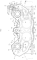
- FIGS. 1 to 9 are views showing an embodiment of a vehicular disc brake and a friction pad of the invention, in which an arrow A indicates a rotation direction of a disc rotor that rotates integrally with wheels when a vehicle is moving forward, and a disc turn-out side and a disc turn-in side to be described later indicate those when the vehicle is moving forward.
- a vehicular disc brake 1 includes: a disc rotor 2 that rotates integrally with wheels (not shown) in an arrow A direction; a caliper body 3 attached to a vehicle body on one side of the disc rotor 2; and a pair of friction pads 5, 5 that are arranged inside the caliper body 3 so as to face each other with the disc rotor 2 interposed therebetween and are suspended by a hanger pin 4.
- a pad spring 6 that prevents rattling of the friction pads 5, 5 abuts against the friction pads 5, 5.
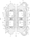
- the opposing-vehicle-body-side caliper half body 21 includes an action portion 21b in which cylinder portions 21a, 21a each having a cylinder hole 22 into which a piston 8 is inserted are arranged side by side in the disc circumferential direction, and a bridge portion half body 21c constituting substantially half of the bridge portion 3a
- the vehicle-body-side caliper half body 31 also includes an action portion 31b in which cylinder portions 31a, 31a each having a cylinder hole 32 into which the piston 8 is inserted are arranged side by side in the disc circumferential direction, and a bridge portion half body 31c constituting substantially half of the bridge portion 3a, similar to the opposing-vehicle-body-side caliper half body 21.
- an opposing-vehicle-body-side ceiling opening portion 21d and a vehicle-body-side ceiling opening portion 31d, which constitute substantially half of the ceiling opening portion 3b, are formed in the bridge portion half body 21c and the bridge portion half body 31c, respectively.
- a union hole 26 opening to a disc turn-out side surface 21f of the bridge portion half body 21c and the first working fluid introduction hole 24 is provided on the disc turn-out side of the bridge portion half body 21c, and a female screw portion 26a into which a union bolt (not shown) is screwed is formed on an opening side of the union hole 26.
- the action portion 21b of the opposing-vehicle-body-side caliper half body 21 includes the cylinder portions 21a, 21a having the cylinder holes 22, 22, a turn-out side body portion 21g extending from the cylinder portion 21a on the disc turn-out side to the disc turn-out side, and a turn-in side body portion 21j extending from the cylinder portion 21a on the disc turn-in side to the disc turn-in side.
- a pair of first reinforcing ribs 28, 28 are provided on the disc radial outer side and the disc radial inner side of an opposing disc rotor side surface 21h of the turn-out side body portion 21g, and the first reinforcing rib 28 on the disc radial outer side connects the cylinder portion 21a on the disc turn-out side and the large-diameter flange portion 27b on the disc radial outer side of the vehicle body attachment portion 27 on the disc turn-out side.
- first reinforcing rib 28 on the disc radial inner side connects the cylinder portion 21a on the disc turn-out side and the large-diameter flange portion 27b on the disc radial inner side of the vehicle body attachment portion 27 on the disc turn-out side.
- a first thinning portion 21i serving as a thin-walled portion is formed, by casting, on the opposing disc rotor side surface 21h between the first reinforcing ribs 28, 28.
- a pair of second reinforcing ribs 29, 29 are provided on the disc radial outer side and the disc radial inner side of the opposing disc rotor side surface 21h of the turn-in side body portion 21j, and the second reinforcing rib 29 on the disc radial outer side connects the cylinder portion 21a on the disc turn-in side and the large-diameter flange portion 27b on the disc radial outer side of the vehicle body attachment portion 27 on the disc turn-in side.
- the second reinforcing rib 29 on the disc radial inner side connects the cylinder portion 21a on the disc turn-in side and the large-diameter flange portion 27b on the disc radial inner side of the vehicle body attachment portion 27 on the disc turn-in side.
- a second thinning portion 21k serving as a thin-walled portion is formed, by casting, on the opposing disc rotor side surface 21h between the second reinforcing ribs 29, 29.
- an outer surface (opposing disc rotor side surface) OS1 of each first reinforcing rib 28 is formed to be gradually inclined toward a disc rotor side toward the disc turn-out side than an outer surface OS2 (opposing disc rotor side surface) of the cylinder portion 21a, and similarly, an outer surface (opposing disc rotor side surface) OS3 of each second reinforcing rib 29 is also formed to be gradually inclined toward the disc rotor side toward the disc turn-in side than the outer surface OS2 (opposing disc rotor side surface) of the cylinder portion 21a.
- a part of the bottom of the cylinder hole 32 on the disc turn-out side includes a fourth contouring machining portion 35a that allows the hydraulic pressure chamber 33 on the disc turn-out side and the second working fluid introduction hole 34 to communicate with each other by a contouring process, and a fifth contouring machining portion 35b that is contoured toward the hydraulic pressure chamber 33 on the disc turn-in side. Further, a part of the bottom of the cylinder hole 32 on the disc turn-in side includes a sixth contouring machining portion 35c that is contoured toward the fifth contouring machining portion 35b.
- the action portion 31b of the vehicle-body-side caliper half body 31 includes the cylinder portions 31a, 31a having the cylinder holes 32, 32, a turn-out side body portion 31g extending from the cylinder portion 31a on the disc turn-out side to the disc turn-out side, and a turn-in side body portion 31j extending from the cylinder portion 31a on the disc turn-in side to the disc turn-in side.
- the caliper body 3 is formed by bonding the opposing-vehicle-body-side caliper half body 21 and the vehicle-body-side caliper half body 31, which are formed as described above, to each other at the bridge portion 3a with the divided surfaces 21e, 31e abutting against each other, and coupling the opposing-vehicle-body-side caliper half body 21 and the vehicle-body-side caliper half body 31 with the coupling bolts 7, 7.
- the end surfaces 6k, 6k of the first elastic piece 6f and the end surfaces 6n, 6n of the second elastic portion 6e abut against the wall portions 3c, 3c on the opposing disc rotor side of the ceiling opening portion 3b, so that unstable movement due to running vibration of a pad spring can be prevented.
- abutting surfaces of the wall portions 3c, 3c against which the end surfaces 6k, 6k, 6n, 6n abut are casting surfaces, processing cost can be reduced.
- the end surfaces 6k, 6k, 6n, 6n including the first positioning piece 6g and the second positioning piece 6h and the bent portion 6m are formed in an arc shape, a contact area can be effectively obtained.
Landscapes
- Engineering & Computer Science (AREA)
- General Engineering & Computer Science (AREA)
- Mechanical Engineering (AREA)
- Braking Arrangements (AREA)
Applications Claiming Priority (2)
| Application Number | Priority Date | Filing Date | Title |
|---|---|---|---|
| JP2021141945 | 2021-08-31 | ||
| PCT/JP2022/032571 WO2023032974A1 (ja) | 2021-08-31 | 2022-08-30 | 車両用ディスクブレーキ及び摩擦パッド |
Publications (2)
| Publication Number | Publication Date |
|---|---|
| EP4397882A1 true EP4397882A1 (de) | 2024-07-10 |
| EP4397882A4 EP4397882A4 (de) | 2025-09-10 |
Family
ID=85411253
Family Applications (1)
| Application Number | Title | Priority Date | Filing Date |
|---|---|---|---|
| EP22864556.0A Pending EP4397882A4 (de) | 2021-08-31 | 2022-08-30 | Scheibenbremse und reibungsklotz für ein fahrzeug |
Country Status (5)
| Country | Link |
|---|---|
| EP (1) | EP4397882A4 (de) |
| JP (1) | JPWO2023032974A1 (de) |
| CN (1) | CN117157471A (de) |
| BR (1) | BR112023021700A2 (de) |
| WO (1) | WO2023032974A1 (de) |
Family Cites Families (16)
| Publication number | Priority date | Publication date | Assignee | Title |
|---|---|---|---|---|
| DE1525385A1 (de) * | 1966-01-10 | 1970-02-05 | Teves Gmbh Alfred | Teilbelagscheibenbremse |
| JPS57179435A (en) * | 1981-04-27 | 1982-11-05 | Akebono Brake Ind Co Ltd | Holder spring used in integral knuckle type disk brake |
| FR2585794B1 (fr) * | 1985-07-31 | 1987-11-13 | Bendix France | Ensemble de patin de friction equipe d'un ressort anti-bruit pour frein a disque |
| JP3257734B2 (ja) * | 1993-11-17 | 2002-02-18 | トキコ株式会社 | ディスクブレーキ |
| DE4442795A1 (de) * | 1994-12-01 | 1996-06-05 | Teves Gmbh Alfred | Niederhaltefeder für Scheibenbremsen |
| JPH09229110A (ja) * | 1996-02-23 | 1997-09-02 | Nissin Kogyo Kk | 車両用ディスクブレーキ |
| JP4250108B2 (ja) * | 2004-03-30 | 2009-04-08 | 日信工業株式会社 | 車両用ディスクブレーキ |
| FR2876427B1 (fr) * | 2004-10-08 | 2008-03-14 | Bosch Gmbh Robert | Element de friction muni d'un moyen de rappel et frein a disque comportant un tel element de friction |
| DE102005001482A1 (de) * | 2005-01-12 | 2006-07-20 | Gustav Magenwirth Gmbh & Co. Kg | Bremszange und Bremsbelag für eine Bremszange |
| JP4668844B2 (ja) * | 2006-05-29 | 2011-04-13 | 曙ブレーキ工業株式会社 | 対向ピストン型ディスクブレーキ |
| JP4857203B2 (ja) * | 2007-06-26 | 2012-01-18 | 日立オートモティブシステムズ株式会社 | ディスクブレーキ |
| JP5607015B2 (ja) * | 2011-11-30 | 2014-10-15 | 日信工業株式会社 | 車両用ディスクブレーキ |
| JP6686852B2 (ja) * | 2016-11-18 | 2020-04-22 | 株式会社アドヴィックス | ピストン対向型のディスクブレーキ |
| US20190120308A1 (en) * | 2017-10-19 | 2019-04-25 | Hb Performance Systems, Inc. | Anti-rattle spring for brake caliper assembly |
| JP2020159369A (ja) * | 2019-03-25 | 2020-10-01 | 日信工業株式会社 | 車両用ディスクブレーキ |
| EP4105512A4 (de) * | 2020-02-12 | 2024-03-20 | Hitachi Astemo, Ltd. | Fahrzeug-scheibenbremse |
-
2022
- 2022-08-30 EP EP22864556.0A patent/EP4397882A4/de active Pending
- 2022-08-30 JP JP2023545598A patent/JPWO2023032974A1/ja active Pending
- 2022-08-30 WO PCT/JP2022/032571 patent/WO2023032974A1/ja not_active Ceased
- 2022-08-30 BR BR112023021700A patent/BR112023021700A2/pt unknown
- 2022-08-30 CN CN202280026464.2A patent/CN117157471A/zh active Pending
Also Published As
| Publication number | Publication date |
|---|---|
| CN117157471A (zh) | 2023-12-01 |
| EP4397882A4 (de) | 2025-09-10 |
| JPWO2023032974A1 (de) | 2023-03-09 |
| BR112023021700A2 (pt) | 2023-12-19 |
| WO2023032974A1 (ja) | 2023-03-09 |
Similar Documents
| Publication | Publication Date | Title |
|---|---|---|
| US6116384A (en) | Disk brake | |
| US8439171B2 (en) | Vehicle disk brake | |
| EP0747608B1 (de) | Scheibenbremse | |
| JP7753494B2 (ja) | 車両用ディスクブレーキ | |
| EP3809009B1 (de) | Fahrzeugscheibenbremse | |
| US20060289253A1 (en) | Monoblock caliper housing for a disc brake assembly | |
| EP4397882A1 (de) | Scheibenbremse und reibungsklotz für ein fahrzeug | |
| EP0087876B1 (de) | Bremssattel für Scheibenbremsen | |
| US9353809B2 (en) | Vehicle disc brake | |
| EP4397883A1 (de) | Sattelkörper für fahrzeugscheibenbremse | |
| EP4253176A1 (de) | Sattelkörper einer scheibenbremse für ein fahrzeug | |
| JP2021173312A (ja) | 浮動型キャリパ | |
| US20110180354A1 (en) | Disc Brake | |
| EP3954921A1 (de) | Scheibenbremsvorrichtung | |
| US20240344574A1 (en) | Return spring and disc brake | |
| JPH1163041A (ja) | 車両用ディスクブレーキのキャリパボディ | |
| JP5603797B2 (ja) | 車両用ディスクブレーキ | |
| EP4265935B1 (de) | Sattelkörper für fahrzeugscheibenbremse | |
| JP7312797B2 (ja) | 車両用ディスクブレーキのキャリパボディ | |
| JP2002161931A (ja) | ディスクブレーキ | |
| JP2020159369A (ja) | 車両用ディスクブレーキ | |
| JPH1130252A (ja) | 車両用ディスクブレーキの分割型キャリパ | |
| WO2025013668A1 (ja) | ディスクブレーキ | |
| JPH07180733A (ja) | 車両用ディスクブレーキ | |
| JPH10238566A (ja) | ディスクブレーキ |
Legal Events
| Date | Code | Title | Description |
|---|---|---|---|
| STAA | Information on the status of an ep patent application or granted ep patent |
Free format text: STATUS: THE INTERNATIONAL PUBLICATION HAS BEEN MADE |
|
| PUAI | Public reference made under article 153(3) epc to a published international application that has entered the european phase |
Free format text: ORIGINAL CODE: 0009012 |
|
| STAA | Information on the status of an ep patent application or granted ep patent |
Free format text: STATUS: REQUEST FOR EXAMINATION WAS MADE |
|
| 17P | Request for examination filed |
Effective date: 20231116 |
|
| AK | Designated contracting states |
Kind code of ref document: A1 Designated state(s): AL AT BE BG CH CY CZ DE DK EE ES FI FR GB GR HR HU IE IS IT LI LT LU LV MC MK MT NL NO PL PT RO RS SE SI SK SM TR |
|
| DAV | Request for validation of the european patent (deleted) | ||
| DAX | Request for extension of the european patent (deleted) | ||
| RAP3 | Party data changed (applicant data changed or rights of an application transferred) |
Owner name: ASTEMO, LTD. |
|
| A4 | Supplementary search report drawn up and despatched |
Effective date: 20250813 |
|
| RIC1 | Information provided on ipc code assigned before grant |
Ipc: F16D 65/02 20060101AFI20250807BHEP Ipc: F16D 65/095 20060101ALI20250807BHEP Ipc: F16D 65/097 20060101ALI20250807BHEP Ipc: F16D 55/225 20060101ALI20250807BHEP Ipc: F16D 55/228 20060101ALI20250807BHEP |