EP4397809A2 - Culée de pont pourvue de parties préfabriquées en béton, ainsi que son procédé de fabrication - Google Patents
Culée de pont pourvue de parties préfabriquées en béton, ainsi que son procédé de fabrication Download PDFInfo
- Publication number
- EP4397809A2 EP4397809A2 EP24174136.2A EP24174136A EP4397809A2 EP 4397809 A2 EP4397809 A2 EP 4397809A2 EP 24174136 A EP24174136 A EP 24174136A EP 4397809 A2 EP4397809 A2 EP 4397809A2
- Authority
- EP
- European Patent Office
- Prior art keywords
- abutment
- wall
- base
- elements
- concrete
- Prior art date
- Legal status (The legal status is an assumption and is not a legal conclusion. Google has not performed a legal analysis and makes no representation as to the accuracy of the status listed.)
- Pending
Links
- 239000004567 concrete Substances 0.000 title claims abstract description 47
- 238000000034 method Methods 0.000 title claims abstract description 29
- 238000004519 manufacturing process Methods 0.000 title description 3
- 239000011178 precast concrete Substances 0.000 claims abstract description 57
- 230000002787 reinforcement Effects 0.000 claims abstract description 55
- 238000009415 formwork Methods 0.000 claims abstract description 30
- 238000011065 in-situ storage Methods 0.000 claims abstract description 25
- 238000010276 construction Methods 0.000 claims abstract description 11
- 238000009434 installation Methods 0.000 claims abstract description 3
- 230000015572 biosynthetic process Effects 0.000 claims abstract 2
- 239000011150 reinforced concrete Substances 0.000 claims description 7
- 238000005266 casting Methods 0.000 claims 1
- 238000007792 addition Methods 0.000 description 3
- 238000003780 insertion Methods 0.000 description 2
- 230000037431 insertion Effects 0.000 description 2
- 239000013589 supplement Substances 0.000 description 2
- 230000007704 transition Effects 0.000 description 2
- 229910001294 Reinforcing steel Inorganic materials 0.000 description 1
- 230000001133 acceleration Effects 0.000 description 1
- 230000003014 reinforcing effect Effects 0.000 description 1
- 230000003068 static effect Effects 0.000 description 1
- 230000002123 temporal effect Effects 0.000 description 1
Images


Classifications
-
- E—FIXED CONSTRUCTIONS
- E01—CONSTRUCTION OF ROADS, RAILWAYS, OR BRIDGES
- E01D—CONSTRUCTION OF BRIDGES, ELEVATED ROADWAYS OR VIADUCTS; ASSEMBLY OF BRIDGES
- E01D19/00—Structural or constructional details of bridges
- E01D19/02—Piers; Abutments ; Protecting same against drifting ice
-
- E—FIXED CONSTRUCTIONS
- E02—HYDRAULIC ENGINEERING; FOUNDATIONS; SOIL SHIFTING
- E02D—FOUNDATIONS; EXCAVATIONS; EMBANKMENTS; UNDERGROUND OR UNDERWATER STRUCTURES
- E02D27/00—Foundations as substructures
- E02D27/01—Flat foundations
- E02D27/02—Flat foundations without substantial excavation
Definitions
- Bridge abutments are very individually designed structures, which are therefore traditionally constructed using formwork manufactured on site as a reinforced concrete structure made of reinforcing steel and in-situ concrete.
- the formwork and demolding work in particular are time-consuming and impair the affected traffic routes.
- the EN 20 2019 100 831 U1 and EN 20 2019 104 913 U1 are therefore already working on accelerating the construction process, which is essentially achieved through the use of special precast concrete elements. It is first necessary to pour a blind layer, onto which precast elements for the abutment wall are then placed and poured with in-situ concrete.
- DE 24 39 466 A1 deals with methods for constructing a substructure for a bridge and with prefabricated parts for this purpose.
- the prefabricated parts are connected horizontally by cast-in-place concrete beams.
- the prefabricated parts are provided with a trench-shaped recess in their head area.
- the invention now presented was based on the aim of developing a bridge abutment that can be constructed even more quickly and with even less traffic restriction, as well as a method for its production. This aim is achieved by a method according to claim 1 and a bridge abutment according to claim 5.
- the precast concrete facade element essentially has a wall shape, i.e. its width and height are considerably greater than the thickness of the base.
- the precast concrete facade element can have lateral recesses, i.e. side recesses where the base adjoins the base of an adjacent precast concrete facade element when the bridge abutment is erected. If adjacent precast concrete facade elements each have such side recesses, reinforcement can be inserted into them. When the cavities of the abutment wall are then poured with in-situ concrete, the adjacent precast concrete facade elements are connected to one another and further stabilized.
- the side recesses can have projections and/or recesses so that they interlock firmly with the in-situ concrete to be filled and the inserted reinforcement.
- the base can also have one or more bored pile recesses at least on the bottom, which can also extend completely, usually vertically, through the base. This means that the base can be placed on bored piles that may have been previously installed for a deep foundation, connected to their reinforcement in a suitable manner and filled accordingly.
- the base of the precast concrete facade element preferably has protruding connecting reinforcements at its lower end on the inside opposite the outside for connection to a base plate of the bridge abutment to be constructed. If no spur is provided on the opposite outside, connecting reinforcements can also protrude from the base there in order to create a spur in in-situ concrete at the installation site if necessary.
- precast concrete facade elements are placed next to each other as intended. If necessary, suitable reinforcement bodies are inserted into existing side recesses. Reinforcement is then inserted above the base, spanning the adjacent precast concrete facade elements, after which the back or inside of the abutment wall to be constructed is closed with formwork elements, which can also be precast elements. To ensure that in-situ concrete poured into the resulting cavity wall does not run out at the sides, the sides of the abutment wall to be constructed must also be closed with formwork elements, which according to the invention are formed by wing wall elements.
- bridge abutments with cast-in-place concrete additions of different depths in the vertical direction can be easily realized.
- very deep cast-in-place concrete additions that form more than 30% of the abutment wall, preferably more than 50% of the abutment wall in a cross-section in the vertical direction can be easily realized using precast concrete facade elements with an L-shaped cross-section.
- precast facade concrete elements with an L-shaped cross-section are less susceptible to damage during transport and/or erection of the precast concrete elements and enable easier insertion of reinforcement cages.
- the depth of the cast-in-place concrete supplement is selected depending on the position of the abutments for a superstructure of the bridge and the respective load distribution angles in the area of the bridge abutment so that the load introduced at an abutment is distributed by the cast-in-place concrete supplement to more than one precast concrete element, in particular at least to the adjacent precast concrete elements.
- the abutment wall can be constructed completely independently of the other parts of the construction.
- a base plate does not have to be concreted beforehand, since the abutment wall is stable on its own and can also be connected to the base plate to be constructed afterwards. Since the abutment wall forms the bridge support, it is essential for the speed of construction of the entire structure that it is constructed as quickly as possible and with minimal temporal impact on traffic due to the construction work.
- the method according to the invention enables the entire new bridge structure to be constructed, preferably with only a single closure of the traffic under the bridge for the new construction work. since no formwork removal work is necessary on the outside of the abutment wall or the facade.
- precast concrete facade elements with side recesses in the base area, whereby reinforcement must be introduced into the area of these recesses between two adjacent precast concrete facade elements.
- These areas can be cast separately with in-situ concrete or preferably when the upper cavity of the abutment wall is cast, whereby the precast concrete facade elements are fixed to one another in the base area in addition to their monolithic connection above the base.
- All precast concrete elements used are preferably reinforced with reinforcement and are usually designed as precast reinforced concrete elements.
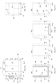
- Fig.2 with Figures 2 a), 2 b), 2 c), 2 d), 2 e), 2 f) shows top left in Fig. 2 a) the right bridge abutment in section AA. There is also indicated where the Figures 2 b) to 2 e) shown sections BB to EE.
- the bridge abutment 1 consists on its freely visible outside of precast concrete facade elements 6, one or more formwork elements 7 for the inside, abutment wall reinforcement 8, an in-situ concrete filling and one or more bearing bases 9.
- the precast concrete facade element 6 has a base 11 on the bottom, the thickness of which corresponds to the entire abutment wall.
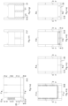
- an abutment reinforcement preferably in the form of a pre-woven reinforcement cage 8 in the direction of arrow P above the base 11 on a ledge formed by it, slipped over protruding connecting reinforcements.
- the spacing of the reinforcement bars of the reinforcement cage 8 is dimensioned such that the reinforcement bars of the abutment reinforcement 8 do not collide with those of the connecting reinforcement 24 of the wing wall elements 27, 28. A slightly offset arrangement is optimal for this.
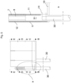
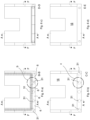
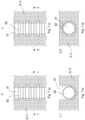
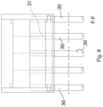
- the Fig. 5 to 8 show the special features of another embodiment of the bridge abutment 1 according to the invention, where a deep foundation was made with bored piles 30, small bored piles or micro piles. These were previously inserted into the subsoil. If, as shown, bored piles 30 are also arranged below the abutment wall, the prefabricated concrete facade parts 6 of the abutment wall can have bored pile recesses 31 in their bases 11. As shown, these can preferably pass completely through the base 11.
- the Bored pile recesses 31 can be made as in Fig.7 with the Figures 7 a) to 7 d) shown also have projections and recesses, into which precisely fitting reinforcement cages 32 (see also Fig.7 ) can be inserted.
Landscapes
- Engineering & Computer Science (AREA)
- Mining & Mineral Resources (AREA)
- Civil Engineering (AREA)
- Structural Engineering (AREA)
- Life Sciences & Earth Sciences (AREA)
- General Life Sciences & Earth Sciences (AREA)
- Paleontology (AREA)
- General Engineering & Computer Science (AREA)
- Architecture (AREA)
- Bridges Or Land Bridges (AREA)
Applications Claiming Priority (2)
| Application Number | Priority Date | Filing Date | Title |
|---|---|---|---|
| DE102021102625.3A DE102021102625A1 (de) | 2021-02-04 | 2021-02-04 | Brückenwiderlager mit Betonfertigteilen sowie Verfahren zu dessen Herstellung |
| EP22155046.0A EP4039884B1 (fr) | 2021-02-04 | 2022-02-03 | Culée de pont pourvue de parties préfabriquées en béton, ainsi que son procédé de fabrication |
Related Parent Applications (2)
| Application Number | Title | Priority Date | Filing Date |
|---|---|---|---|
| EP22155046.0A Division EP4039884B1 (fr) | 2021-02-04 | 2022-02-03 | Culée de pont pourvue de parties préfabriquées en béton, ainsi que son procédé de fabrication |
| EP22155046.0A Division-Into EP4039884B1 (fr) | 2021-02-04 | 2022-02-03 | Culée de pont pourvue de parties préfabriquées en béton, ainsi que son procédé de fabrication |
Publications (2)
| Publication Number | Publication Date |
|---|---|
| EP4397809A2 true EP4397809A2 (fr) | 2024-07-10 |
| EP4397809A3 EP4397809A3 (fr) | 2024-09-18 |
Family
ID=80225396
Family Applications (2)
| Application Number | Title | Priority Date | Filing Date |
|---|---|---|---|
| EP24174136.2A Pending EP4397809A3 (fr) | 2021-02-04 | 2022-02-03 | Culée de pont pourvue de parties préfabriquées en béton, ainsi que son procédé de fabrication |
| EP22155046.0A Active EP4039884B1 (fr) | 2021-02-04 | 2022-02-03 | Culée de pont pourvue de parties préfabriquées en béton, ainsi que son procédé de fabrication |
Family Applications After (1)
| Application Number | Title | Priority Date | Filing Date |
|---|---|---|---|
| EP22155046.0A Active EP4039884B1 (fr) | 2021-02-04 | 2022-02-03 | Culée de pont pourvue de parties préfabriquées en béton, ainsi que son procédé de fabrication |
Country Status (2)
| Country | Link |
|---|---|
| EP (2) | EP4397809A3 (fr) |
| DE (2) | DE102021102625A1 (fr) |
Citations (3)
| Publication number | Priority date | Publication date | Assignee | Title |
|---|---|---|---|---|
| DE2439466A1 (de) | 1974-08-16 | 1976-02-26 | Frank Dipl Ing Buechting | Verfahren zur erstellung des unterbaues einer bruecke |
| DE202019100831U1 (de) | 2019-02-13 | 2019-03-25 | Bauunternehmen Echterhoff Gmbh & Co. Kg | Brückenwiderlager und Brückenbauwerk |
| KR102181805B1 (ko) | 2019-10-21 | 2020-11-24 | (주)지승씨앤아이 | 무조인트 교량의 수직벽체형 블록 조립유닛 및 이를 이용한 무조인트 교량 조립 시공방법 |
Family Cites Families (3)
| Publication number | Priority date | Publication date | Assignee | Title |
|---|---|---|---|---|
| CA2237867A1 (fr) | 1995-11-14 | 1997-05-22 | Jada Ab | Technique de construction de pont et pont edifie selon cette technique |
| FR2824851B1 (fr) | 2001-05-18 | 2003-12-12 | Soc Civ D Brevets Matiere | Appui de pont prefabrique |
| KR101585652B1 (ko) * | 2014-10-20 | 2016-01-14 | 주식회사 장헌산업 | 중공벽체와 강재기둥을 이용하여 지반과 구조물간의 상호작용 및 온도신축변위를 차단하는 구조의 교대를 가지는 교대일체식 교량 |
-
2021
- 2021-02-04 DE DE102021102625.3A patent/DE102021102625A1/de active Pending
-
2022
- 2022-02-03 DE DE202022100635.0U patent/DE202022100635U1/de active Active
- 2022-02-03 EP EP24174136.2A patent/EP4397809A3/fr active Pending
- 2022-02-03 EP EP22155046.0A patent/EP4039884B1/fr active Active
Patent Citations (4)
| Publication number | Priority date | Publication date | Assignee | Title |
|---|---|---|---|---|
| DE2439466A1 (de) | 1974-08-16 | 1976-02-26 | Frank Dipl Ing Buechting | Verfahren zur erstellung des unterbaues einer bruecke |
| DE202019100831U1 (de) | 2019-02-13 | 2019-03-25 | Bauunternehmen Echterhoff Gmbh & Co. Kg | Brückenwiderlager und Brückenbauwerk |
| DE202019104913U1 (de) | 2019-02-13 | 2019-10-22 | Bauunternehmen Echterhoff Gmbh & Co. Kg | Brückenwiderlager mit Verbindung zwischen Widerlagerwandbewehrung und Flügelwandelement |
| KR102181805B1 (ko) | 2019-10-21 | 2020-11-24 | (주)지승씨앤아이 | 무조인트 교량의 수직벽체형 블록 조립유닛 및 이를 이용한 무조인트 교량 조립 시공방법 |
Also Published As
| Publication number | Publication date |
|---|---|
| EP4397809A3 (fr) | 2024-09-18 |
| EP4039884C0 (fr) | 2024-06-12 |
| EP4039884A1 (fr) | 2022-08-10 |
| DE102021102625A1 (de) | 2022-08-04 |
| DE202022100635U1 (de) | 2022-03-04 |
| EP4039884B1 (fr) | 2024-06-12 |
Similar Documents
| Publication | Publication Date | Title |
|---|---|---|
| DE69611931T2 (de) | Unterirdisches bauwerk, insbesondere für die herstellung von tunnels, unterführungen, tiefgaragen, etc. und sein herstellungsverfahren | |
| AT404273B (de) | Verschalung mit einer vielzahl von miteinander verbindbaren leichtgewicht-verschalungselementen | |
| EP2025816B1 (fr) | Procédé de fabrication d'un élément de muret et élément de muret fabriqué après le procédé pour un muret de séparation du trafic | |
| EP4039884B1 (fr) | Culée de pont pourvue de parties préfabriquées en béton, ainsi que son procédé de fabrication | |
| DE202019102588U1 (de) | Befestigung eines Brückenüberbaus und dabei zu verwendendes Randabschlusselement | |
| EP3702533B1 (fr) | Procédé de fixation d'une superstructure de pont et élément de bordure destiné à être utilisé à cet effet | |
| DE2660867C2 (de) | Verfahren zur Errichtung trichter- oder kegelförmiger Betonbauten | |
| DE60002318T2 (de) | Verfahren zur bildung eines wasserdichtes und die kriechgrenze steigernden abschnittes | |
| DE10018979A1 (de) | Wandelement | |
| EP3299524B1 (fr) | Mur en elements prefabriques et son procede de fabrication | |
| EP3696320B1 (fr) | Culée de pont pourvu de raccordement entre une armature de paroi de coulée et un élément de paroi ailée | |
| WO2003104562A1 (fr) | Element beton prefabrique et procede | |
| WO2004065087A2 (fr) | Coffrage rabattable | |
| EP1210485B1 (fr) | Piece en beton arme pour fondations pour batiments | |
| DE69006144T2 (de) | Verfahren zur Herstellung von Bauwerken, insbesondere von Eisenbahnunterführungen. | |
| DE2803860C2 (de) | Verfahren zur Herstellung einer Stützmauer | |
| DE9320679U1 (de) | Montage- und Reparaturgrube | |
| DE69801084T2 (de) | Verfahren zum unterfangen einer wand oder tragmauer | |
| DE3837850C2 (de) | Wandtafel und Schalungsstein | |
| EP3412848A2 (fr) | Fosse de montage à double paroi des éléments de paroi | |
| DE1634531A1 (de) | Verfahren zur Herstellung von Stuetzmauern unter Verwendung von vorgefertigten Betonwaenden | |
| DE29915343U1 (de) | Stahlbetonteil zur Herstellung von Fundamenten für Bauwerke | |
| DE2548298C2 (de) | Verfahren und Hohlraumverschalungswand zum Bauen einer Hohlmauer | |
| AT522502B1 (de) | Verfahren zur Betoneinbringung bei einer horizontalen Gleitbauweise in Ortbetonbauweise, Vorrichtung zur Herstellung eines horizontalen Betonelements | |
| AT367130B (de) | Verfahren zum herstellen einer schlitzwand im erdboden, erster pfeilerartiger betonfertigteil, formkasten und zweiter platten- foermiger betonfertigteil zur durchfuehrung des verfahrens |
Legal Events
| Date | Code | Title | Description |
|---|---|---|---|
| PUAI | Public reference made under article 153(3) epc to a published international application that has entered the european phase |
Free format text: ORIGINAL CODE: 0009012 |
|
| STAA | Information on the status of an ep patent application or granted ep patent |
Free format text: STATUS: THE APPLICATION HAS BEEN PUBLISHED |
|
| AC | Divisional application: reference to earlier application |
Ref document number: 4039884 Country of ref document: EP Kind code of ref document: P |
|
| AK | Designated contracting states |
Kind code of ref document: A2 Designated state(s): AL AT BE BG CH CY CZ DE DK EE ES FI FR GB GR HR HU IE IS IT LI LT LU LV MC MK MT NL NO PL PT RO RS SE SI SK SM TR |
|
| PUAL | Search report despatched |
Free format text: ORIGINAL CODE: 0009013 |
|
| AK | Designated contracting states |
Kind code of ref document: A3 Designated state(s): AL AT BE BG CH CY CZ DE DK EE ES FI FR GB GR HR HU IE IS IT LI LT LU LV MC MK MT NL NO PL PT RO RS SE SI SK SM TR |
|
| RIC1 | Information provided on ipc code assigned before grant |
Ipc: E01D 19/02 20060101AFI20240809BHEP |
|
| STAA | Information on the status of an ep patent application or granted ep patent |
Free format text: STATUS: REQUEST FOR EXAMINATION WAS MADE |
|
| 17P | Request for examination filed |
Effective date: 20250312 |