EP4397356A1 - Krankenhaus-flüssigkeitsabgabewandsteckdose mit ineinandergreifender haube - Google Patents
Krankenhaus-flüssigkeitsabgabewandsteckdose mit ineinandergreifender haube Download PDFInfo
- Publication number
- EP4397356A1 EP4397356A1 EP23209804.6A EP23209804A EP4397356A1 EP 4397356 A1 EP4397356 A1 EP 4397356A1 EP 23209804 A EP23209804 A EP 23209804A EP 4397356 A1 EP4397356 A1 EP 4397356A1
- Authority
- EP
- European Patent Office
- Prior art keywords
- socket
- wall
- cover
- expansions
- fluid
- Prior art date
- Legal status (The legal status is an assumption and is not a legal conclusion. Google has not performed a legal analysis and makes no representation as to the accuracy of the status listed.)
- Pending
Links
Images



Classifications
-
- A—HUMAN NECESSITIES
- A61—MEDICAL OR VETERINARY SCIENCE; HYGIENE
- A61M—DEVICES FOR INTRODUCING MEDIA INTO, OR ONTO, THE BODY; DEVICES FOR TRANSDUCING BODY MEDIA OR FOR TAKING MEDIA FROM THE BODY; DEVICES FOR PRODUCING OR ENDING SLEEP OR STUPOR
- A61M39/00—Tubes, tube connectors, tube couplings, valves, access sites or the like, specially adapted for medical use
- A61M39/10—Tube connectors; Tube couplings
- A61M39/1011—Locking means for securing connection; Additional tamper safeties
-
- A—HUMAN NECESSITIES
- A61—MEDICAL OR VETERINARY SCIENCE; HYGIENE
- A61G—TRANSPORT, PERSONAL CONVEYANCES, OR ACCOMMODATION SPECIALLY ADAPTED FOR PATIENTS OR DISABLED PERSONS; OPERATING TABLES OR CHAIRS; CHAIRS FOR DENTISTRY; FUNERAL DEVICES
- A61G12/00—Accommodation for nursing, e.g. in hospitals, not covered by groups A61G1/00 - A61G11/00, e.g. trolleys for transport of medicaments or food; Prescription lists
- A61G12/002—Supply appliances, e.g. columns for gas, fluid, electricity supply
- A61G12/005—Supply appliances, e.g. columns for gas, fluid, electricity supply mounted on the wall
-
- F—MECHANICAL ENGINEERING; LIGHTING; HEATING; WEAPONS; BLASTING
- F16—ENGINEERING ELEMENTS AND UNITS; GENERAL MEASURES FOR PRODUCING AND MAINTAINING EFFECTIVE FUNCTIONING OF MACHINES OR INSTALLATIONS; THERMAL INSULATION IN GENERAL
- F16L—PIPES; JOINTS OR FITTINGS FOR PIPES; SUPPORTS FOR PIPES, CABLES OR PROTECTIVE TUBING; MEANS FOR THERMAL INSULATION IN GENERAL
- F16L37/00—Couplings of the quick-acting type
- F16L37/60—Couplings of the quick-acting type with plug and fixed wall housing
-
- A—HUMAN NECESSITIES
- A61—MEDICAL OR VETERINARY SCIENCE; HYGIENE
- A61M—DEVICES FOR INTRODUCING MEDIA INTO, OR ONTO, THE BODY; DEVICES FOR TRANSDUCING BODY MEDIA OR FOR TAKING MEDIA FROM THE BODY; DEVICES FOR PRODUCING OR ENDING SLEEP OR STUPOR
- A61M16/00—Devices for influencing the respiratory system of patients by gas treatment, e.g. ventilators; Tracheal tubes
- A61M16/20—Valves specially adapted to medical respiratory devices
- A61M16/208—Non-controlled one-way valves, e.g. exhalation, check, pop-off non-rebreathing valves
-
- A—HUMAN NECESSITIES
- A61—MEDICAL OR VETERINARY SCIENCE; HYGIENE
- A61M—DEVICES FOR INTRODUCING MEDIA INTO, OR ONTO, THE BODY; DEVICES FOR TRANSDUCING BODY MEDIA OR FOR TAKING MEDIA FROM THE BODY; DEVICES FOR PRODUCING OR ENDING SLEEP OR STUPOR
- A61M39/00—Tubes, tube connectors, tube couplings, valves, access sites or the like, specially adapted for medical use
- A61M39/10—Tube connectors; Tube couplings
- A61M2039/1027—Quick-acting type connectors
-
- A—HUMAN NECESSITIES
- A61—MEDICAL OR VETERINARY SCIENCE; HYGIENE
- A61M—DEVICES FOR INTRODUCING MEDIA INTO, OR ONTO, THE BODY; DEVICES FOR TRANSDUCING BODY MEDIA OR FOR TAKING MEDIA FROM THE BODY; DEVICES FOR PRODUCING OR ENDING SLEEP OR STUPOR
- A61M39/00—Tubes, tube connectors, tube couplings, valves, access sites or the like, specially adapted for medical use
- A61M39/22—Valves or arrangement of valves
- A61M39/24—Check- or non-return valves
- A61M2039/2473—Valve comprising a non-deformable, movable element, e.g. ball-valve, valve with movable stopper or reciprocating element
- A61M2039/248—Ball-valve
-
- A—HUMAN NECESSITIES
- A61—MEDICAL OR VETERINARY SCIENCE; HYGIENE
- A61M—DEVICES FOR INTRODUCING MEDIA INTO, OR ONTO, THE BODY; DEVICES FOR TRANSDUCING BODY MEDIA OR FOR TAKING MEDIA FROM THE BODY; DEVICES FOR PRODUCING OR ENDING SLEEP OR STUPOR
- A61M39/00—Tubes, tube connectors, tube couplings, valves, access sites or the like, specially adapted for medical use
- A61M39/22—Valves or arrangement of valves
- A61M39/24—Check- or non-return valves
- A61M2039/2473—Valve comprising a non-deformable, movable element, e.g. ball-valve, valve with movable stopper or reciprocating element
- A61M2039/2486—Guided stem, e.g. reciprocating stopper
-
- A—HUMAN NECESSITIES
- A61—MEDICAL OR VETERINARY SCIENCE; HYGIENE
- A61M—DEVICES FOR INTRODUCING MEDIA INTO, OR ONTO, THE BODY; DEVICES FOR TRANSDUCING BODY MEDIA OR FOR TAKING MEDIA FROM THE BODY; DEVICES FOR PRODUCING OR ENDING SLEEP OR STUPOR
- A61M2202/00—Special media to be introduced, removed or treated
- A61M2202/02—Gases
- A61M2202/0208—Oxygen
-
- A—HUMAN NECESSITIES
- A61—MEDICAL OR VETERINARY SCIENCE; HYGIENE
- A61M—DEVICES FOR INTRODUCING MEDIA INTO, OR ONTO, THE BODY; DEVICES FOR TRANSDUCING BODY MEDIA OR FOR TAKING MEDIA FROM THE BODY; DEVICES FOR PRODUCING OR ENDING SLEEP OR STUPOR
- A61M2202/00—Special media to be introduced, removed or treated
- A61M2202/02—Gases
- A61M2202/0266—Nitrogen (N)
- A61M2202/0283—Nitrous oxide (N2O)
-
- A—HUMAN NECESSITIES
- A61—MEDICAL OR VETERINARY SCIENCE; HYGIENE
- A61M—DEVICES FOR INTRODUCING MEDIA INTO, OR ONTO, THE BODY; DEVICES FOR TRANSDUCING BODY MEDIA OR FOR TAKING MEDIA FROM THE BODY; DEVICES FOR PRODUCING OR ENDING SLEEP OR STUPOR
- A61M2205/00—General characteristics of the apparatus
- A61M2205/75—General characteristics of the apparatus with filters
Definitions
- Fluid distribution wall outlets are commonly used in healthcare establishments, such as hospitals, clinics or the like. They are arranged at the outlet of fluid networks, typically pipes, which convey medical fluids to the rooms where the fluid(s) are used, for example operating and/or treatment rooms, patient rooms or others.
- Wall outlets are used to distribute medical fluids which are conveyed by the fluid networks to the equipment or flexible pipes connected to them, in particular medical gases, such as oxygen, medical air or nitrous oxide (N 2 O), carbon dioxide (CO 2 ) or even vacuum (ie depression) allowing aspirations to be carried out, in particular of biological liquids, for example blood or other biological liquids, during patient care.
- medical gases such as oxygen, medical air or nitrous oxide (N 2 O), carbon dioxide (CO 2 ) or even vacuum (ie depression) allowing aspirations to be carried out, in particular of biological liquids, for example blood or other biological liquids, during patient care.
- a wall socket is attached to a wall by integrating into it directly or indirectly.
- a fluid distribution wall socket comprises a socket body crossed by an axial fluid passage used to convey the fluid, i.e. gas or vacuum.
- the fluid passage fluidly connects a proximal end provided with a socket head shaped to allow connection to equipment or a flexible pipe, to an opposite distal end to which a fluid pipe is connected.
- a valve seat and a movable valve shutter, arranged in the main fluid passage make it possible to control fluid circulation in the main passage, in particular the supply of gas or vacuum.
- the socket head which is located at the proximal end of the wall socket, projects outwards so as to allow its connection to medical equipment using or conveying the fluid, for example a healthcare appliance or device, a flexible pipe or the like.
- a socket also includes an external cover forming a sort of shield or wall used to protect the socket against shocks and dirt, i.e. dust deposits, projections, etc. which may occur during use of the socket in a hospital environment, for example during an operation.
- This cover is positioned around the socket head, that is to say the proximal end of the socket body. When the cover is placed in position, the plug head passes through a central opening in the cover to project outwards and can be connected to a device, a device or a flexible pipe connecting to it.
- the cover can be held by a nut screwed onto the socket body or be fixed to the technical sheath or to the box within which the fluid socket is arranged.
- these ways of fixing the fluid intake pose problems or cause inconveniences.
- Fluid connection systems are taught by US2020/0345997 And US2013/0167841 but none of these relate to a hospital wall outlet for dispensing fluid, particularly medical fluids.
- the present invention aims to resolve all or part of these problems or disadvantages, by improving and simplifying the fixing of the cover of a hospital wall socket for distributing fluid, in particular medical fluids, i.e. gas or vacuum (depression).
- fluid in particular medical fluids, i.e. gas or vacuum (depression).
- the solution of the invention then relates to a wall socket for distributing fluid, i.e. gas or vacuum, typically a hospital wall socket, comprising an axis socket body (AA) comprising a peripheral wall, i.e. external, an internal housing and a distal end, and a socket cover comprising a cover opening through which the socket body passes, typically a central opening.
- AA axis socket body
- the grip cover comprises several wall expansions projecting along the axis (AA) towards the distal end of the grip body, and said wall expansions are integral with the cover body and each comprise a shaped free end, i.e. configured, to cooperate with the peripheral wall of the socket body to secure the cover to the socket body.
- the invention also relates to a sheath, a ceiling arm or a fluid distribution socket box comprising at least one fluid distribution socket according to the invention.
- the fluid distribution socket(s) are connected to a gas or vacuum pipes, in particular the network of gas or vacuum pipes (ie depression) of a hospital building.
- the fluid is oxygen, air, or nitrous oxide.
- the invention also relates to a use of a fluid distribution outlet according to the invention for supplying a fluid to a medical device or device, in particular a gas or vacuum (i.e. depression or suction).
- a fluid distribution outlet for supplying a fluid to a medical device or device, in particular a gas or vacuum (i.e. depression or suction).
- the installation of the socket cover on the socket is simply done by inserting the proximal end of the socket which carries the socket head , in the central opening of the hood body.
- the wall expansions located on the rear face of the cover then translate in the direction of the fixing structure carried by the peripheral wall of the socket body, i.e. groove, groove or annular wall, until they cooperate with this fixing structure via their radial shoulder, in particular the radial shoulder of each wall expansion abuts against a reciprocal fixing structure carried by the socket body so as to ensure fixing of the cover to the socket body, that is to say via a sort of “clipping” or interlocking, and to oppose any subsequent unwanted removal or detachment of these elements.
- Fig. 1 represents a fluid distribution sheath 20 comprising here 4 juxtaposed fluid distribution outlets 1 making it possible to supply medical gases and vacuum, that is to say a depression ( ⁇ 1 atm), within a hospital building , for example in a treatment room or an operating room.
- medical gases and vacuum that is to say a depression ( ⁇ 1 atm)
- the fluid intakes 1 are embedded in the sheath 20 which has the shape of an elongated box, and which is itself fixed to a wall 21 or a wall of the hospital building.
- the sheath 20 may also include other elements, such as electrical connection sockets 22.
- the 4 outlets provide medical air, medical oxygen, nitrous oxide or MEOPA, ie equimolar mixture (50% mol./50% mol.) of oxygen and nitrous oxide (N 2 O), and vacuum.
- nitrous oxide ie equimolar mixture (50% mol./50% mol.) of oxygen and nitrous oxide (N 2 O), and vacuum.
- it can be used to supply another gas or gas mixture.
- Each socket 1 is provided with a socket cover 10 comprising a central opening 11 through which the socket body 2 passes, in particular the socket cover 10 according to the invention as described below.
- This exterior cover 10 forms a sort of front shield serving to protect the socket 1 against shocks and dirt, i.e. dust deposits, projections, etc. which may occur during the use of the socket 1 in question, for example during care of a patient.
- the sheath 20 can receive fluid intakes 1 according to the invention, such as that presented in Fig. 2 to Fig. 8 and described below.
- Fig. 5 is a magnified view of one of the fluid intakes 1 arranged in the sheath 20 of Fig. 1 .
- the socket 1 is equipped with a socket cover 10 according to the invention, of which the architecture is detailed below in relation to Fig. 2 to Fig. 4 , Fig. 6 And Fig. 7 which propose an embodiment of a cover 10 for fluid intake 1 according to the invention.
- Fig. 2 , Fig. 6 And Fig. 7 show the cover 10 detached from the socket 1, that is to say before its fixing or its attachment to the fluid socket 1.
- the socket cover 10 comprises a cover opening 11, that is to say a central opening, and here has the general shape of a flat or convex disc. It comprises two opposite faces 10-1, 10-2, namely a front face 10-1, or facade, directed outwards and a rear face 10-2, or back, opposite the front face 10-1, that is to say rear towards the rear of socket 1, i.e. towards wall 21.
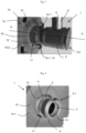
- the grip cover 10 comprises several wall expansions 12 which are integral with the cover body 2, for example at least 4 wall expansions 12, as better visible on Fig. 6 And Fig. 7 . They each include a free end 12-1 shaped or configured to cooperate with the peripheral wall 4 of the socket body 2 to secure the cover 10 to the socket body 2, as illustrated in Fig. 3 and Fig. 4 .
- the socket cover 10 comprises 4 wall expansions 12 angularly distributed around the central opening 11 (and the axis XX), that is to say angularly offset from each other by approximately 90°.
- the 4 wall expansions 12 are separated from each other by intermediate walls 16 of arcuate shape, as visible on Fig. 6 And Fig. 7 , namely here 4 intermediate walls 16.
- the wall expansions 12 project at the rear of the body 2 of grip cover 10 and extend along the axis (AA), towards the distal end 2-2 of the grip body 2, when the cover 2 has been threaded or inserted through the central opening 11 of the cover 2, this is when the socket body 2 passes through the central opening 11.
- the wall expansions 12 form hooking, fixing, lashing, holding tabs or tabs or the like. To do this, they each comprise a free end 12-1 carrying (at least) a radial shoulder 13 directed towards the axis (AA), that is to say a small structure in relief projecting towards the socket body 2, as schematized in Fig. 8 .
- the shoulder 13 is provided over all or part of the width of the end 12-1 of the wall expansions 12.
- the wall expansions 12, such as tabs or tabs, have a structure in the form of an elongated strip which can be flat or slightly curved to match the external contour of the socket body 2 of cylindrical shape.
- the radial shoulders 13 constitute lashing 'hooks' or 'claws' or similar. Each radial shoulder 13 cooperates with the peripheral wall 4 of the socket body 2, that is to say its external wall, to secure the cover 10 to the socket body 2 and prevent or oppose its removal from the socket body. socket 2.
- the socket body 2 has a general tubular shape, as visible in Fig. 3 .
- the wall expansions 12, forming securing tabs or tabs are slightly flexible to facilitate their installation by nesting or the like around the gripping body 2. Their relative flexibility or elasticity is conferred by the strip shape and the polymer material from which the wall expansions 12 are formed.
- the intermediate walls 16 located between the wall expansions 12 do not include radial shoulders 13 constituting 'hooks' or 'claws' for securing or the like.
- the intermediate walls 16 are more rigid than the flexible wall expansions 12.
- the wall expansions may have a length of 5 to 15 mm, preferably of the order of 8 to 12 mm, the radial shoulder of each wall expansion a size of 1 to 4 mm, and each expansion wall width between 3 and 10 mm.
- the socket cover 10 comprises a plane P, for example a plane P passing through the cover body when it is flat, which is perpendicular to the axis (AA) of the socket body 2.
- a fixing structure 4-1 is arranged, preferably one (or more) annular grooves or one (or more) annular walls, in or on the peripheral wall 4, over all or part of the periphery of the body of socket 2 (ie around the cylindrical body), for example one (or more) annular groove or groove, so that the shoulder 13 of the wall expansions 12 of the socket cover 10 comes into contact abutment against this fixing structure 4-1 carried by the peripheral wall 4 of the socket body 2 to prevent any removal of the socket cover 10 from the socket body 2.
- the wall expansions 12, the optional intermediate walls 16, and the rest of the cover 10 are formed in one piece, preferably by injection molding of a polymer material, while the grip body 2 is as to him machined from metal, for example copper alloy or stainless steel.
- Fig. 3 shows the distal part 2-2 of the fluid distribution socket 1, that is to say its rear part, equipped with the socket cover 10 according to the invention.
- the shoulders 13 of the wall expansions 12 cooperate, i.e. abut, against a thread or the like constituting the fixing structure 4-1, which is arranged around the peripheral wall 4 of the grip body 2.
- This thread comprises a thread, that is to say schematically a succession of grooves or grooves arranged substantially parallel to one another.
- the optional intermediate walls 16 do not cooperate with the fixing structure 4-1 arranged around the peripheral wall 4 of the socket body 2.
- the shoulders 13 of the wall expansions 12 attach to the thread of the thread forming the fixing structure 4-1 of the grip body 2 but not the optional intermediate walls 16.
- the socket cover 10 comprises a peripheral rim which is not completely circular since it includes a cutout or notch 17 making it possible to receive the hinge 23 of the pivoting socket cover (not shown), as illustrated in Fig. 5 .
- the wall expansions 12, that is to say tongues or the like, and the intermediate walls 16 are carried, that is to say fixed to their non-free end, by an annular base 14 arranged around the opening 11 of the cover, on the rear face of the cover 10-2, that is to say a reinforced structure located at the base of the wall expansions 12 and arranged coaxially with the central opening 11 of the cover 10.
- the cover 2 can schematically "clip", that is to say fit, directly onto the body 2 of the fluid intake 1 and the radial shoulders 13 forming hooks or lashing claws or similar, secure or hang on the 4-1 external thread of socket 1.
- a tube 15 makes it possible to fluidly connect the socket body 2 to a fluid supply pipe, for example to the hospital network, in order to supply the socket 1 with fluid, i.e. gas or vacuum. Such a connection is classic and not detailed here.
- Fig. 4 shows the proximal part 2-1 of the fluid intake 1, ie gas or vacuum, equipped with the cover 10 according to the invention.
- the front face 10-1 of the cover 1 which is directed outwards, that is to say towards the socket head 5 projecting outwards, to which medical equipment is connected (not watch).
- the socket head 5 includes the outlet 5-1 of the socket 1 through which the gas exits or allows suction by vacuum (i.e. depression).
- the 5-1 outlet port of the socket is located at the proximal end
- the socket body 2 has an internal architecture and operation similar or identical to those described by EP-A-3892906 .
- the socket body 2 comprises a removable tip guide 200 comprising a hollow support part 201 of generally tubular (ie cylindrical) shape with a blind bottom, that is to say comprising an internal compartment closed at one end, comprising fluid filtration membranes, and an internal passage 202 through which the fluid, ie gas, can circulate.
- the tip guide 200 including the gas outlet orifice 5-1.
- the filtration membranes arranged in the peripheral wall of the support part 201 of generally tubular shape have pores or meshes of sizes between 50 and 300 ⁇ m, preferably between 50 and 80 ⁇ m. They are crossed by the fluid which passes through them as it passes through the tip guide 200.
- the ball chamber 206 preferably extractable, is aimed at the bottom of the grip body 2, in particular in the upstream part of the internal housing 3 forming an axial passage of the grip body 2.
- the ball chamber 206 is therefore taken into account. sandwich between the grip base and the extractable bit guide 200.
- the grip body 2 has an elongated shape along a longitudinal axis AA, which is crossed axially by the internal passage forming an internal housing 3 within which the tip guide 200 and the ball chamber 206 are arranged. fixing the tip guide 200 within the passage or housing 3 of the body 2 of the fluid distribution socket 1, the latter comprises an external peripheral thread cooperating with a tapping provided in the wall of the passage 3 of the socket body 2 .
- the fluid socket 1 of the invention can be inserted into a socket box capable of receiving a single socket 1 at a time, for example a socket box as described by EP-A-3932468 , or else a sheath 20 or a ceiling arm, or be directly fixed to a wall 240, such as a wall, a partition or the like, of a hospital establishment, by means of means of fixing to a partition or the like (not detailed).
- a socket box capable of receiving a single socket 1 at a time
- a socket box as described by EP-A-3932468
- a sheath 20 or a ceiling arm or be directly fixed to a wall 240, such as a wall, a partition or the like, of a hospital establishment, by means of means of fixing to a partition or the like (not detailed).
Landscapes
- Health & Medical Sciences (AREA)
- Engineering & Computer Science (AREA)
- Veterinary Medicine (AREA)
- General Engineering & Computer Science (AREA)
- Heart & Thoracic Surgery (AREA)
- Life Sciences & Earth Sciences (AREA)
- Animal Behavior & Ethology (AREA)
- General Health & Medical Sciences (AREA)
- Public Health (AREA)
- Nursing (AREA)
- Mechanical Engineering (AREA)
- Pulmonology (AREA)
- Anesthesiology (AREA)
- Biomedical Technology (AREA)
- Hematology (AREA)
- Branch Pipes, Bends, And The Like (AREA)
- Infusion, Injection, And Reservoir Apparatuses (AREA)
- Closures For Containers (AREA)
- Containers And Packaging Bodies Having A Special Means To Remove Contents (AREA)
Applications Claiming Priority (1)
| Application Number | Priority Date | Filing Date | Title |
|---|---|---|---|
| FR2300018A FR3144642B1 (fr) | 2023-01-03 | 2023-01-03 | Prise de distribution de fluide à capot emboité |
Publications (1)
| Publication Number | Publication Date |
|---|---|
| EP4397356A1 true EP4397356A1 (de) | 2024-07-10 |
Family
ID=86272524
Family Applications (1)
| Application Number | Title | Priority Date | Filing Date |
|---|---|---|---|
| EP23209804.6A Pending EP4397356A1 (de) | 2023-01-03 | 2023-11-14 | Krankenhaus-flüssigkeitsabgabewandsteckdose mit ineinandergreifender haube |
Country Status (2)
| Country | Link |
|---|---|
| EP (1) | EP4397356A1 (de) |
| FR (1) | FR3144642B1 (de) |
Citations (11)
| Publication number | Priority date | Publication date | Assignee | Title |
|---|---|---|---|---|
| FR2323090A1 (fr) * | 1974-01-10 | 1977-04-01 | Air Liquide | Raccord a verrouillage automatique et elements internes demontables pour canalisation de fluide |
| FR2628820A1 (fr) | 1988-03-18 | 1989-09-22 | Air Liquide | Raccord a verrouillage automatique pour fluides medicaux |
| EP2306060A1 (de) | 2009-09-30 | 2011-04-06 | L'AIR LIQUIDE, Société Anonyme pour l'Etude et l'Exploitation des Procédés Georges Claude | Fluidverteilungsanschluss, insbesondere für medizinisches Gas oder Vakuum |
| US20130167841A1 (en) | 2012-01-03 | 2013-07-04 | General Electric Company | Apparatus, System, and Method of Fluid Delivery Connection |
| US20180339146A1 (en) * | 2015-11-25 | 2018-11-29 | Bayer Healthcare Llc | Syringe and connector system |
| US20200345997A1 (en) | 2011-08-10 | 2020-11-05 | Fisher & Paykel Healthcare Limited | Conduit connector for a patient breathing device |
| EP3892906A1 (de) | 2020-04-10 | 2021-10-13 | Air Liquide Medical Systems | Fluidverteilungsanschluss mit herausziebarer ventilkugelkammer zur verwendung in einer krankenhausumgebung |
| EP3922894A1 (de) | 2020-06-10 | 2021-12-15 | Air Liquide Medical Systems | Wandanschlussführung für die ausgabe von fluiden aus zwei stoffen |
| EP3922339A1 (de) | 2020-06-10 | 2021-12-15 | Air Liquide Medical Systems | Wandanschluss-führung für die fluidausgabe, die ein filterelement mit kontrollierter porosität umfasst |
| EP3922895A1 (de) | 2020-06-10 | 2021-12-15 | Air Liquide Medical Systems | Filterelement einer wandanschlussführung für die ausgabe von fluiden |
| EP3932468A2 (de) | 2020-06-29 | 2022-01-05 | Air Liquide Medical Systems | Flüssigkeitsverteiler, geschützt durch einen starren kasten für die verwendung in krankenhauseinstellungen |
-
2023
- 2023-01-03 FR FR2300018A patent/FR3144642B1/fr active Active
- 2023-11-14 EP EP23209804.6A patent/EP4397356A1/de active Pending
Patent Citations (11)
| Publication number | Priority date | Publication date | Assignee | Title |
|---|---|---|---|---|
| FR2323090A1 (fr) * | 1974-01-10 | 1977-04-01 | Air Liquide | Raccord a verrouillage automatique et elements internes demontables pour canalisation de fluide |
| FR2628820A1 (fr) | 1988-03-18 | 1989-09-22 | Air Liquide | Raccord a verrouillage automatique pour fluides medicaux |
| EP2306060A1 (de) | 2009-09-30 | 2011-04-06 | L'AIR LIQUIDE, Société Anonyme pour l'Etude et l'Exploitation des Procédés Georges Claude | Fluidverteilungsanschluss, insbesondere für medizinisches Gas oder Vakuum |
| US20200345997A1 (en) | 2011-08-10 | 2020-11-05 | Fisher & Paykel Healthcare Limited | Conduit connector for a patient breathing device |
| US20130167841A1 (en) | 2012-01-03 | 2013-07-04 | General Electric Company | Apparatus, System, and Method of Fluid Delivery Connection |
| US20180339146A1 (en) * | 2015-11-25 | 2018-11-29 | Bayer Healthcare Llc | Syringe and connector system |
| EP3892906A1 (de) | 2020-04-10 | 2021-10-13 | Air Liquide Medical Systems | Fluidverteilungsanschluss mit herausziebarer ventilkugelkammer zur verwendung in einer krankenhausumgebung |
| EP3922894A1 (de) | 2020-06-10 | 2021-12-15 | Air Liquide Medical Systems | Wandanschlussführung für die ausgabe von fluiden aus zwei stoffen |
| EP3922339A1 (de) | 2020-06-10 | 2021-12-15 | Air Liquide Medical Systems | Wandanschluss-führung für die fluidausgabe, die ein filterelement mit kontrollierter porosität umfasst |
| EP3922895A1 (de) | 2020-06-10 | 2021-12-15 | Air Liquide Medical Systems | Filterelement einer wandanschlussführung für die ausgabe von fluiden |
| EP3932468A2 (de) | 2020-06-29 | 2022-01-05 | Air Liquide Medical Systems | Flüssigkeitsverteiler, geschützt durch einen starren kasten für die verwendung in krankenhauseinstellungen |
Non-Patent Citations (1)
| Title |
|---|
| BAYER MATERIAL SCIENCE: "Snap-Fit Joints for Plastics", 9 March 2012 (2012-03-09), pages 1 - 26, XP093072526, Retrieved from the Internet <URL:https://fab.cba.mit.edu/classes/S62.12/people/vernelle.noel/Plastic_Snap_fit_design.pdf> [retrieved on 20230810] * |
Also Published As
| Publication number | Publication date |
|---|---|
| FR3144642A1 (fr) | 2024-07-05 |
| FR3144642B1 (fr) | 2025-04-11 |
Similar Documents
| Publication | Publication Date | Title |
|---|---|---|
| EP3719377B1 (de) | Wandanordnung mit einem anschluss für die ausgabe eines medizinischen fluids mit verbesserter befestigung und indexierung | |
| EP3922895B1 (de) | Filterelement einer wandanschlussführung für die ausgabe von fluiden | |
| FR2616071A1 (fr) | Tube de tracheostomie avec une canule interieure amovible equipe d'un anneau de traction | |
| EP3922894B1 (de) | Wandanschlussführung für die ausgabe von fluiden aus zwei stoffen | |
| EP2306060B1 (de) | Fluidverteilungsanschluss, insbesondere für medizinisches Gas oder Vakuum | |
| EP3922339B1 (de) | Wandanschluss-führung für die fluidausgabe, die ein filterelement mit kontrollierter porosität umfasst | |
| FR2980688A1 (fr) | Chariot de transport d'une bouteille de gaz medical | |
| EP3892906B1 (de) | Fluidverteilungsanschluss mit herausziebarer ventilkugelkammer zur verwendung in einer krankenhausumgebung | |
| EP3875136B1 (de) | Medizinisches ventilationsgerät mit einem anschlussstutzen, der einen leicht entfernbaren filter enthält | |
| EP3932468A2 (de) | Flüssigkeitsverteiler, geschützt durch einen starren kasten für die verwendung in krankenhauseinstellungen | |
| FR3144642A1 (fr) | Prise de distribution de fluide à capot emboité | |
| FR3015298A1 (fr) | Ensemble hydraulique de generateur de jets pulses ou non pulses moyenne et haute pression | |
| FR3020438A1 (fr) | Electrovanne a moyen de montage ameliore de tubulures sur celle-ci | |
| CA2670641C (fr) | Dispositif de montage d'un filtre concu avec entrave a la rotation | |
| FR3111405A1 (fr) | Guide-embout de prise murale de distribution avec marquage d’identification unique | |
| EP1611921A1 (de) | Medizinische Steckdose zur Verwendung medizinischer Flüssigkeiten | |
| EP4175878B1 (de) | Filterhalteradapter für atemwegsverwendung | |
| FR3112187A1 (fr) | Prise murale de distribution de fluide médical à tubulure matricée | |
| FR2960154A1 (fr) | Element de jonction pour des composants dans un systeme de ventilation | |
| FR3106181A1 (fr) | Prise de distribution de fluide médical avec guide-embout extractible à face avant colorée | |
| FR2902488A1 (fr) | Appareil de fourniture de gaz | |
| FR3115345A1 (fr) | Embase et point de prélèvement de gaz comportant une embase | |
| FR3106182A1 (fr) | Prise de distribution de fluide médical revêtue de nickel | |
| EP0322358B1 (de) | Versorgungsvorrichtung für mehrere Fluide in Mehrfachleitungen | |
| EP2977671A1 (de) | Anordnung zur Verteilung von medizinischem Gas |
Legal Events
| Date | Code | Title | Description |
|---|---|---|---|
| PUAI | Public reference made under article 153(3) epc to a published international application that has entered the european phase |
Free format text: ORIGINAL CODE: 0009012 |
|
| STAA | Information on the status of an ep patent application or granted ep patent |
Free format text: STATUS: THE APPLICATION HAS BEEN PUBLISHED |
|
| AK | Designated contracting states |
Kind code of ref document: A1 Designated state(s): AL AT BE BG CH CY CZ DE DK EE ES FI FR GB GR HR HU IE IS IT LI LT LU LV MC ME MK MT NL NO PL PT RO RS SE SI SK SM TR |
|
| STAA | Information on the status of an ep patent application or granted ep patent |
Free format text: STATUS: REQUEST FOR EXAMINATION WAS MADE |
|
| 17P | Request for examination filed |
Effective date: 20250110 |
|
| STAA | Information on the status of an ep patent application or granted ep patent |
Free format text: STATUS: EXAMINATION IS IN PROGRESS |
|
| 17Q | First examination report despatched |
Effective date: 20251104 |