EP3875136B1 - Medizinisches ventilationsgerät mit einem anschlussstutzen, der einen leicht entfernbaren filter enthält - Google Patents
Medizinisches ventilationsgerät mit einem anschlussstutzen, der einen leicht entfernbaren filter enthält Download PDFInfo
- Publication number
- EP3875136B1 EP3875136B1 EP21151993.9A EP21151993A EP3875136B1 EP 3875136 B1 EP3875136 B1 EP 3875136B1 EP 21151993 A EP21151993 A EP 21151993A EP 3875136 B1 EP3875136 B1 EP 3875136B1
- Authority
- EP
- European Patent Office
- Prior art keywords
- socket
- ventilator
- filter
- internal
- internal passage
- Prior art date
- Legal status (The legal status is an assumption and is not a legal conclusion. Google has not performed a legal analysis and makes no representation as to the accuracy of the status listed.)
- Active
Links
Images



Classifications
-
- A—HUMAN NECESSITIES
- A61—MEDICAL OR VETERINARY SCIENCE; HYGIENE
- A61M—DEVICES FOR INTRODUCING MEDIA INTO, OR ONTO, THE BODY; DEVICES FOR TRANSDUCING BODY MEDIA OR FOR TAKING MEDIA FROM THE BODY; DEVICES FOR PRODUCING OR ENDING SLEEP OR STUPOR
- A61M16/00—Devices for influencing the respiratory system of patients by gas treatment, e.g. ventilators; Tracheal tubes
- A61M16/08—Bellows; Connecting tubes ; Water traps; Patient circuits
-
- A—HUMAN NECESSITIES
- A61—MEDICAL OR VETERINARY SCIENCE; HYGIENE
- A61M—DEVICES FOR INTRODUCING MEDIA INTO, OR ONTO, THE BODY; DEVICES FOR TRANSDUCING BODY MEDIA OR FOR TAKING MEDIA FROM THE BODY; DEVICES FOR PRODUCING OR ENDING SLEEP OR STUPOR
- A61M16/00—Devices for influencing the respiratory system of patients by gas treatment, e.g. ventilators; Tracheal tubes
- A61M16/08—Bellows; Connecting tubes ; Water traps; Patient circuits
- A61M16/0816—Joints or connectors
-
- A—HUMAN NECESSITIES
- A61—MEDICAL OR VETERINARY SCIENCE; HYGIENE
- A61M—DEVICES FOR INTRODUCING MEDIA INTO, OR ONTO, THE BODY; DEVICES FOR TRANSDUCING BODY MEDIA OR FOR TAKING MEDIA FROM THE BODY; DEVICES FOR PRODUCING OR ENDING SLEEP OR STUPOR
- A61M16/00—Devices for influencing the respiratory system of patients by gas treatment, e.g. ventilators; Tracheal tubes
- A61M16/10—Preparation of respiratory gases or vapours
- A61M16/1005—Preparation of respiratory gases or vapours with O2 features or with parameter measurement
- A61M16/101—Preparation of respiratory gases or vapours with O2 features or with parameter measurement using an oxygen concentrator
-
- A—HUMAN NECESSITIES
- A61—MEDICAL OR VETERINARY SCIENCE; HYGIENE
- A61M—DEVICES FOR INTRODUCING MEDIA INTO, OR ONTO, THE BODY; DEVICES FOR TRANSDUCING BODY MEDIA OR FOR TAKING MEDIA FROM THE BODY; DEVICES FOR PRODUCING OR ENDING SLEEP OR STUPOR
- A61M2202/00—Special media to be introduced, removed or treated
- A61M2202/02—Gases
- A61M2202/0208—Oxygen
Definitions
- the invention relates to a medical ventilator equipped with a connection socket for supplying the ventilator with a medical gas, typically oxygen, in particular a socket of the NIST or DISS type.
- fluid distribution networks i.e. the pipes carrying medical fluids, such as gas or vacuum (i.e. depression/suction), end with wall sockets fixed to the walls of the buildings to which medical devices consuming gas or requiring vacuum to operate can be connected.
- medical fluids such as gas or vacuum (i.e. depression/suction)
- BM wall sockets fixed to the walls of the buildings to which medical devices consuming gas or requiring vacuum to operate
- connection sockets for medical ventilators i.e. those integrated into the ventilators
- the most used to supply gases are the NIST (Non Interchangeable Screw-Threaded Connecter) and DISS (Diameter Index Safety System) type sockets.
- These connection sockets are mounted directly on respiratory assistance devices, i.e. medical ventilators, used to supply a breathing gas, for example air or oxygen-enriched air, to patients suffering from respiratory disorders.
- connection socket of a medical ventilator is in fluid communication with the internal gas circuit or path of the medical ventilator and also ensures the connection of an external medical gas source supplying the medical ventilator.
- it can be supplied with oxygen so as to be able to enrich with oxygen, the air supplied by the micro-blower of the medical ventilator to the patient, that is to say to produce a flow of air enriched with oxygen (i.e. O 2 content > 21% vol.).
- connection sockets for medical ventilators usually comprise a socket body axially crossed by an internal passage comprising means for controlling the flow of gas in the internal passage, namely generally a movable valve cooperating with a valve seat, typically a silicone valve or the like.
- a known problem is related to the internal pollution of the socket and the internal gas circuit of the medical ventilator by dust or other particulate pollutants which can enter through the connection socket, and then deteriorate the valve and/or prevent a good fluid seal from being ensured by it.
- gas sources are not all perfectly clean and, moreover, the storage and/or non-use of medical ventilators for more or less long periods of time can lead to dust or other substances entering the connection sockets of said medical ventilators.
- connection sockets of medical ventilators preferably NIST or DISS type sockets
- the connection plug and disassemble it to remove the filter are to be able to simplify and speed up the maintenance of the connection sockets of medical ventilators, preferably NIST or DISS type sockets, in particular to be able to replace a filter without having to open the medical ventilator, remove the connection plug and disassemble it to remove the filter.
- the solution then concerns a medical ventilator comprising an internal gas circuit in fluid communication with a connection socket arranged on said medical ventilator, i.e. integrated into said ventilator, said connection socket comprising a socket body axially traversed by an internal passage connecting an inlet orifice carried by a free proximal end of the socket body to an outlet orifice, and comprising flow control means for controlling the circulation of gas within said internal passage arranged in the internal passage between the inlet and outlet orifices, and a filtration element arranged in the internal passage of the socket body.
- the filter element is mounted in a removable manner within the internal passage of the socket body, the insertion or extraction, i.e. its assembly/disassembly, of said filter element being carried out via the inlet orifice of the internal passage of the socket body carried by the free proximal end of the socket body, i.e. without there being any need to disassemble or separate the socket and/or to open the medical ventilator.
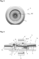
- FIG. 2 is a longitudinal sectional view of an embodiment of a DISS type connection socket 1 for a medical ventilator 10 according to the invention
- the Fig. 4 is a longitudinal sectional view of an embodiment of a NIST type connection socket 1 for a medical ventilator 10 according to the invention, which sockets 1 of the Fig. 2 And Fig. 4 are shown carried by a support piece 11 fixed to the carcass 13 of said medical ventilator 10 (cf. Fig. 6 ), for example by screws or the like, and furthermore fluidly connected, via their distal end 1b, to the internal gas circuit 12 of the medical ventilator 10.
- connection socket 1 for medical ventilator 10 comprises a socket body 2 of elongated shape, i.e. oblong, axially crossed by an internal passage 3 connecting a gas inlet orifice 4 to a gas outlet orifice 5.
- the gas for example oxygen
- the socket body 2 is for example made of nickel-plated brass and is also shaped so that a gas source 20, in particular oxygen, can be mechanically and fluidically connected to it via a gas supply line, such as a flexible pipe or the like, provided with a connector 22 of complementary shape and/or structure, as illustrated in Fig. 6 , coming to connect to the free proximal end 1a of the socket 1.
- a gas source 20 in particular oxygen
- a gas supply line such as a flexible pipe or the like
- flow control means 6, 7 are provided for controlling the circulation of the gas within the internal passage 3, which are arranged in the internal passage 3 between the inlet 4 and outlet 5 ports.
- the flow control means 6, 7 comprise a movable valve 6 cooperating with a valve seat 7, in particular a silicone valve having an umbrella shape, that is to say formed of a rod surmounted by a flat or slightly domed disk.
- a filtration element 8 is arranged in the internal passage 3 of the socket body 2.
- the filtration element 8 can be inserted and fixed directly in the passage 3 or preferably, as in the proposed embodiments, indirectly by being inserted into a filter cartridge 9 comprising a cartridge body 90 axially traversed by an internal conduit 91 within which the filtration element 8 is arranged, as detailed in the Fig. 5 .
- the filtration element 8 is mounted in an extractable manner within the internal passage 3 of the socket body 2, from the proximal end 1a of the socket 1 through the inlet orifice 4 of the socket body 2, that is to say that the insertion or extraction of said filtration element 8 is done via the proximal end 1a and the inlet orifice 4 of the internal passage 3 of the socket body 2 without it being necessary to dissociate the socket 1 from the fan 10 and/or to dismantle the socket 1 itself in order to insert or extract the filtration element 8 therefrom.
- the filter element 8 is a sintered type filter, for example made of bronze, of conical shape here and having pores of diameter small enough to retain solid particulate pollutants and other dust, while allowing the gas which supplies the outlet 1 to pass, for example oxygen to be supplied to the fan 10 by an oxygen source, such as an oxygen cylinder.
- an oxygen source such as an oxygen cylinder.
- the bronze sintered filter with pores of approximately 50 to 100 ⁇ m can be used.
- another type of filter can be used.
- the cartridge body 90 is shaped so as to have a thread 92 on its external peripheral wall 93, which is complementary to a tapping 30 arranged in the inlet region 31 of the passage 3 of the socket body 2 so as to allow fixing by screwing of the filter cartridge 9 within the passage 3 of the socket body 2 as illustrated in the Fig. 2 And Fig. 4 .
- the cartridge body 90 of the filter cartridge 9 also comprises a particular front end 94, namely that it is shaped to be able to be driven in rotation by a screwing tool, when screwing or unscrewing the filter cartridge 9 within the internal passage 3 of the socket body 2, via the proximal end 1a of the socket 1, as visible in the Fig. 1 And Fig. 3 .
- the front end 94 of the cartridge body 90 has a hexagonal-shaped imprint 95 which can cooperate with a 6-sided key.
- the cartridge body 90 has a generally tubular shape comprising several successive sections of different external diameters, namely here a front section S1 of diameter smaller than that of the rear section S2, as illustrated in the Fig. 5 . It can be made of brass or another metal or metal alloy.
- Fig. 6 schematizes a patient ventilation assembly including a medical ventilator 10, i.e. a respiratory assistance device, comprising an external frame or shell 13 carrying the connection socket 1, i.e. the socket 1 according to the invention, which is fixed to the frame 13 by means of, for example, the support part 11 visible in the Fig. 2 And Fig. 4 .
- the socket 1 of the invention projects outwards away from the casing 13 of the fan 10.
- connection socket 1 is advantageously a socket of the NIST or DISS type.
- the socket 1 is of the DISS type, care is taken to ensure that it meets the geometric requirements defined by the CGA V-5-2008 standard, and the geometric requirements of the NF EN ISO 5359 standard when the socket 1 is of the NIST type.
- connection socket 1 equipping a ventilator 10 of the invention is in fluid communication, on the one hand, via its proximal end 1a, with a source of medical gas 20, typically a source of oxygen, for example a compressed oxygen cylinder, supplying the medical gas to the inlet orifice 4 of the socket 1 and, on the other hand, with the internal gas circuit 12 of the medical ventilator 10 in order to supply the medical gas, typically oxygen, to said circuit 12 through the outlet orifice 5 carried by the distal end 1b of the socket 1.
- a source of medical gas typically a compressed oxygen cylinder
- the medical gas source 20 is connected to the ventilator 10 via a flexible gas line 21 or the like provided with a connection connector 22. complementary to the connection socket 1, for example forming together a male/female type connection.
- the ventilator 10 also comprises a gas outlet 14 which is fluidically connected to a patient respiratory interface 40, such as a respiratory mask or the like, via a flexible gas supply pipe 41.
- the 10 ventilator can be used not only in a hospital environment but also in the field, i.e. in an emergency vehicle such as SAMU, SMUR or similar.
Landscapes
- Health & Medical Sciences (AREA)
- Emergency Medicine (AREA)
- Pulmonology (AREA)
- Engineering & Computer Science (AREA)
- Anesthesiology (AREA)
- Biomedical Technology (AREA)
- Heart & Thoracic Surgery (AREA)
- Hematology (AREA)
- Life Sciences & Earth Sciences (AREA)
- Animal Behavior & Ethology (AREA)
- General Health & Medical Sciences (AREA)
- Public Health (AREA)
- Veterinary Medicine (AREA)
- Respiratory Apparatuses And Protective Means (AREA)
Claims (14)
- Medizinisches Beatmungsgerät (10), welches einen inneren Gaskreislauf (12) umfasst, der mit einem an dem medizinischen Beatmungsgerät (10) angeordneten Verbindungsanschluss (1) in Fluidverbindung steht, wobei der Verbindungsanschluss (1) umfasst:- einen Anschlusskörper (2), der axial von einem inneren Durchgang (3) durchquert wird, der eine Einlassöffnung (4), die von einem freien proximalen Ende (1a) des Anschlusskörpers (2) getragen wird, mit einer Auslassöffnung (5) verbindet, und Mittel zur Steuerung des Flusses (6, 7) umfasst, um die Strömung des Gases innerhalb des inneren Durchgangs (3) zu steuern, die in dem inneren Durchgang (3) zwischen der Einlass- (4) und der Auslassöffnung (5) angeordnet sind, wobei die Mittel zur Steuerung des Flusses (6, 7) ein bewegliches Ventil (6) umfassen, das mit einem Ventilsitz (7) zusammenwirkt, und- ein Filterelement (8), das in dem inneren Durchgang (3) des Anschlusskörpers (2) angeordnet ist, wobei das Filterelement (8) herausziehbar innerhalb des inneren Durchgangs (3) des Anschlusskörpers (2) angebracht ist, wobei das Einsetzen oder Herausziehen des Filterelements (8) über die Einlassöffnung (4) des inneren Durchgangs (3) erfolgt, die von dem freien proximalen Ende (1a) des Anschlusskörpers (2) getragen wird, wobei das Filterelement (8) in einer Filterpatrone (9) angeordnet ist, die einen Patronenkörper (90) umfasst, der axial von einem inneren Kanal (91) durchquert wird, der in dem inneren Kanal (91) angeordnet ist,dadurch gekennzeichnet, dass:- das bewegliche Ventil (6) aus Silikon besteht und eine Regenschirmform aufweist, die von einer Stange gebildet wird, die von einer flachen oder leicht gewölbten Scheibe überragt wird, und- das Filterelement (8) ein Sinterfilter oder Gewebefilter ist.
- Beatmungsgerät nach Anspruch 1, dadurch gekennzeichnet, dass der Patronenkörper (90) der Filterpatrone (9) ein Gewinde (92) umfasst, das in seiner äußeren Umfangswand (93) angeordnet ist, um durch Einschrauben in dem inneren Durchgang (3) des Anschlusskörpers (2) befestigt zu werden, wobei wenigstens ein Teil des inneren Durchgangs (3) des Anschlusskörpers (2) ein Innengewinde (30) umfasst, das zu dem von der äußeren Umfangswand (93) des Patronenkörpers (90) getragenen Gewinde (92) komplementär ist.
- Beatmungsgerät nach einem der vorhergehenden Ansprüche, dadurch gekennzeichnet, dass der Patronenkörper (90) der Filterpatrone (9) außerdem ein vorderes Ende (94) umfasst, das dafür ausgebildet ist, beim Einschrauben oder Losschrauben der Filterpatrone (9) innerhalb des inneren Durchgangs (3) des Anschlusskörpers (2) von einem Schraubwerkzeug drehend angetrieben werden zu können.
- Beatmungsgerät nach Anspruch 2, dadurch gekennzeichnet, dass das Innengewinde (30) in einem Eingangsbereich (31) des Durchgangs (3) des Anschlusskörpers (2) angeordnet ist.
- Beatmungsgerät nach Anspruch 3, dadurch gekennzeichnet, dass das vordere Ende (94) des Patronenkörpers (90) eine Einprägung (95) für ein Einschraub-/Lösewerkzeug umfasst.
- Beatmungsgerät nach Anspruch 5, dadurch gekennzeichnet, dass die Einprägung (95) von polygonaler Form ist, vorzugsweise von sechseckiger Form für einen Sechskantschlüssel.
- Beatmungsgerät nach Anspruch 1, dadurch gekennzeichnet, dass das Filterelement (8) ein Sinterfilter aus Bronze oder ein auf einer Halterung aus Polymer angebrachtes Gewebefilter ist.
- Beatmungsgerät nach einem der Ansprüche 1 oder 7, dadurch gekennzeichnet, dass das Filterelement (8) ein kegelförmiges Filter umfasst.
- Beatmungsgerät nach einem der Ansprüche 1, 7 oder 8, dadurch gekennzeichnet, dass das Filterelement (8) ein Sinterfilter umfasst, das Poren mit Durchmessern zwischen ungefähr 60 und 100 µm aufweist.
- Beatmungsgerät nach Anspruch 1, dadurch gekennzeichnet, dass der Verbindungsanschluss (1) aus den Anschlüssen vom Typ NIST oder DISS ausgewählt ist.
- Beatmungsgerät nach Anspruch 1, dadurch gekennzeichnet, dass der innere Gaskreislauf des Beatmungsgerätes (10) außerdem mit einem Mikrogebläse in Fluidverbindung steht.
- Beatmungsgerät nach einem der vorhergehenden Ansprüche, dadurch gekennzeichnet, dass es ein Außengehäuse umfasst, das den Verbindungsanschluss (1) trägt.
- Beatmungsanordnung (10, 20, 40) für einen Patienten, welche umfasst:- ein medizinisches Beatmungsgerät (10), das einen Verbindungsanschluss (1) umfasst, nach einem der vorhergehenden Ansprüche,eine Gasquelle (20), die mit dem Verbindungsanschluss (1) des medizinischen Beatmungsgerätes (10) in Fluidverbindung steht, und- eine Patientenbeatmungsschnittstelle (40), die über einen Gaszuführungsschlauch (41) mit einem Gasauslass (14) des medizinischen Beatmungsgerätes (10) in Fluidverbindung steht.
- Beatmungsanordnung nach Anspruch 13, dadurch gekennzeichnet, dass die Gasquelle (20) eine Sauerstoffquelle ist.
Applications Claiming Priority (1)
| Application Number | Priority Date | Filing Date | Title |
|---|---|---|---|
| FR2002149A FR3107839B1 (fr) | 2020-03-03 | 2020-03-03 | Prise de raccordement pour ventilateur médical à filtre aisément extractible |
Publications (2)
| Publication Number | Publication Date |
|---|---|
| EP3875136A1 EP3875136A1 (de) | 2021-09-08 |
| EP3875136B1 true EP3875136B1 (de) | 2024-10-16 |
Family
ID=71894888
Family Applications (1)
| Application Number | Title | Priority Date | Filing Date |
|---|---|---|---|
| EP21151993.9A Active EP3875136B1 (de) | 2020-03-03 | 2021-01-18 | Medizinisches ventilationsgerät mit einem anschlussstutzen, der einen leicht entfernbaren filter enthält |
Country Status (2)
| Country | Link |
|---|---|
| EP (1) | EP3875136B1 (de) |
| FR (1) | FR3107839B1 (de) |
Families Citing this family (2)
| Publication number | Priority date | Publication date | Assignee | Title |
|---|---|---|---|---|
| CN114432553A (zh) * | 2022-02-08 | 2022-05-06 | 中国人民解放军总医院第八医学中心 | 一种防细菌滋生有创呼吸机 |
| FR3146599B1 (fr) | 2023-03-16 | 2025-04-11 | Air Liquide Medical Systems | Ventilateur médical à circuit d’admission d’air incluant des résonateurs |
Family Cites Families (3)
| Publication number | Priority date | Publication date | Assignee | Title |
|---|---|---|---|---|
| FR2431649A1 (fr) * | 1978-07-19 | 1980-02-15 | Installation Hospitaliere Sani | Prise de gaz medicale et son raccord de jonction |
| EP1611921A1 (de) * | 2004-06-29 | 2006-01-04 | Yog Industries | Medizinische Steckdose zur Verwendung medizinischer Flüssigkeiten |
| DE202013008155U1 (de) * | 2013-09-16 | 2013-10-08 | Praxair Technology, Inc. | Anschlussbaugruppe für Medizinangasanwendungen |
-
2020
- 2020-03-03 FR FR2002149A patent/FR3107839B1/fr active Active
-
2021
- 2021-01-18 EP EP21151993.9A patent/EP3875136B1/de active Active
Also Published As
| Publication number | Publication date |
|---|---|
| FR3107839A1 (fr) | 2021-09-10 |
| EP3875136A1 (de) | 2021-09-08 |
| FR3107839B1 (fr) | 2025-03-07 |
Similar Documents
| Publication | Publication Date | Title |
|---|---|---|
| EP3922895B1 (de) | Filterelement einer wandanschlussführung für die ausgabe von fluiden | |
| EP3719377B1 (de) | Wandanordnung mit einem anschluss für die ausgabe eines medizinischen fluids mit verbesserter befestigung und indexierung | |
| EP3922894B1 (de) | Wandanschlussführung für die ausgabe von fluiden aus zwei stoffen | |
| EP3760262B1 (de) | Medizinisches beatmungsgerät mit innengehäuse, das ein motorisiertes mikrogebläse und gaskreisläufe umfasst | |
| EP3922339B1 (de) | Wandanschluss-führung für die fluidausgabe, die ein filterelement mit kontrollierter porosität umfasst | |
| EP3875136A1 (de) | Medizinisches ventilationsgerät mit einem anschlussstutzen, der einen leicht entfernbaren filter enthält | |
| EP2306060B1 (de) | Fluidverteilungsanschluss, insbesondere für medizinisches Gas oder Vakuum | |
| EP3892906B1 (de) | Fluidverteilungsanschluss mit herausziebarer ventilkugelkammer zur verwendung in einer krankenhausumgebung | |
| EP3093498A1 (de) | Mikrogebläse mit verbesserter abdichtung der motorachse für beatmungsgerät | |
| EP3932468A2 (de) | Flüssigkeitsverteiler, geschützt durch einen starren kasten für die verwendung in krankenhauseinstellungen | |
| FR3098121A1 (fr) | Ventilateur médical avec micro-soufflante motorisée à refroidissement amélioré | |
| FR3106065A1 (fr) | Micro-soufflante à montage radial pour ventilateur médical | |
| EP4397356A1 (de) | Krankenhaus-flüssigkeitsabgabewandsteckdose mit ineinandergreifender haube | |
| FR3118585A1 (fr) | Ventilateur médical à deux entrées d’oxygène et capteur de pression d’oxygène commun | |
| FR3106182A1 (fr) | Prise de distribution de fluide médical revêtue de nickel | |
| EP3482789A1 (de) | Beatmungsgerät mit verbessertem gaskreis | |
| CN111387916A (zh) | 一种吸引结构及具有该吸引结构的内窥镜操作部 | |
| FR3091740A1 (fr) | Prise de distribution de fluide médical à guide-embout extractible | |
| FR3106181A1 (fr) | Prise de distribution de fluide médical avec guide-embout extractible à face avant colorée | |
| FR3086175A1 (fr) | Prise de distribution de fluide, notamment de gaz medical, comprenant une partie centrale de carenage mobile | |
| FR3111405A1 (fr) | Guide-embout de prise murale de distribution avec marquage d’identification unique | |
| WO2015039898A1 (fr) | Cartouche pour circuit pneumatique et dispositif de prehension a ventouse comportant une telle cartouche | |
| FR3091742A1 (fr) | Prise de distribution de gaz avec système de maintien de fuite résiduelle | |
| FR3000678A3 (fr) | Ensemble d'aspiration en circuit ferme, apte a etre mis en place sur un bronchoscope | |
| EP1611921A1 (de) | Medizinische Steckdose zur Verwendung medizinischer Flüssigkeiten |
Legal Events
| Date | Code | Title | Description |
|---|---|---|---|
| PUAI | Public reference made under article 153(3) epc to a published international application that has entered the european phase |
Free format text: ORIGINAL CODE: 0009012 |
|
| STAA | Information on the status of an ep patent application or granted ep patent |
Free format text: STATUS: THE APPLICATION HAS BEEN PUBLISHED |
|
| AK | Designated contracting states |
Kind code of ref document: A1 Designated state(s): AL AT BE BG CH CY CZ DE DK EE ES FI FR GB GR HR HU IE IS IT LI LT LU LV MC MK MT NL NO PL PT RO RS SE SI SK SM TR |
|
| STAA | Information on the status of an ep patent application or granted ep patent |
Free format text: STATUS: REQUEST FOR EXAMINATION WAS MADE |
|
| 17P | Request for examination filed |
Effective date: 20220310 |
|
| RBV | Designated contracting states (corrected) |
Designated state(s): AL AT BE BG CH CY CZ DE DK EE ES FI FR GB GR HR HU IE IS IT LI LT LU LV MC MK MT NL NO PL PT RO RS SE SI SK SM TR |
|
| GRAP | Despatch of communication of intention to grant a patent |
Free format text: ORIGINAL CODE: EPIDOSNIGR1 |
|
| STAA | Information on the status of an ep patent application or granted ep patent |
Free format text: STATUS: GRANT OF PATENT IS INTENDED |
|
| INTG | Intention to grant announced |
Effective date: 20240521 |
|
| GRAS | Grant fee paid |
Free format text: ORIGINAL CODE: EPIDOSNIGR3 |
|
| GRAA | (expected) grant |
Free format text: ORIGINAL CODE: 0009210 |
|
| STAA | Information on the status of an ep patent application or granted ep patent |
Free format text: STATUS: THE PATENT HAS BEEN GRANTED |
|
| AK | Designated contracting states |
Kind code of ref document: B1 Designated state(s): AL AT BE BG CH CY CZ DE DK EE ES FI FR GB GR HR HU IE IS IT LI LT LU LV MC MK MT NL NO PL PT RO RS SE SI SK SM TR |
|
| REG | Reference to a national code |
Ref country code: GB Ref legal event code: FG4D Free format text: NOT ENGLISH |
|
| REG | Reference to a national code |
Ref country code: DE Ref legal event code: R096 Ref document number: 602021020201 Country of ref document: DE Ref country code: CH Ref legal event code: EP |
|
| REG | Reference to a national code |
Ref country code: IE Ref legal event code: FG4D Free format text: LANGUAGE OF EP DOCUMENT: FRENCH |
|
| REG | Reference to a national code |
Ref country code: LT Ref legal event code: MG9D |
|
| REG | Reference to a national code |
Ref country code: NL Ref legal event code: MP Effective date: 20241016 |
|
| REG | Reference to a national code |
Ref country code: AT Ref legal event code: MK05 Ref document number: 1732440 Country of ref document: AT Kind code of ref document: T Effective date: 20241016 |
|
| PG25 | Lapsed in a contracting state [announced via postgrant information from national office to epo] |
Ref country code: NL Free format text: LAPSE BECAUSE OF FAILURE TO SUBMIT A TRANSLATION OF THE DESCRIPTION OR TO PAY THE FEE WITHIN THE PRESCRIBED TIME-LIMIT Effective date: 20241016 |
|
| PG25 | Lapsed in a contracting state [announced via postgrant information from national office to epo] |
Ref country code: NL Free format text: LAPSE BECAUSE OF FAILURE TO SUBMIT A TRANSLATION OF THE DESCRIPTION OR TO PAY THE FEE WITHIN THE PRESCRIBED TIME-LIMIT Effective date: 20241016 |
|
| PG25 | Lapsed in a contracting state [announced via postgrant information from national office to epo] |
Ref country code: PT Free format text: LAPSE BECAUSE OF FAILURE TO SUBMIT A TRANSLATION OF THE DESCRIPTION OR TO PAY THE FEE WITHIN THE PRESCRIBED TIME-LIMIT Effective date: 20250217 Ref country code: HR Free format text: LAPSE BECAUSE OF FAILURE TO SUBMIT A TRANSLATION OF THE DESCRIPTION OR TO PAY THE FEE WITHIN THE PRESCRIBED TIME-LIMIT Effective date: 20241016 Ref country code: IS Free format text: LAPSE BECAUSE OF FAILURE TO SUBMIT A TRANSLATION OF THE DESCRIPTION OR TO PAY THE FEE WITHIN THE PRESCRIBED TIME-LIMIT Effective date: 20250216 |
|
| PG25 | Lapsed in a contracting state [announced via postgrant information from national office to epo] |
Ref country code: FI Free format text: LAPSE BECAUSE OF FAILURE TO SUBMIT A TRANSLATION OF THE DESCRIPTION OR TO PAY THE FEE WITHIN THE PRESCRIBED TIME-LIMIT Effective date: 20241016 |
|
| PG25 | Lapsed in a contracting state [announced via postgrant information from national office to epo] |
Ref country code: BG Free format text: LAPSE BECAUSE OF FAILURE TO SUBMIT A TRANSLATION OF THE DESCRIPTION OR TO PAY THE FEE WITHIN THE PRESCRIBED TIME-LIMIT Effective date: 20241016 |
|
| PG25 | Lapsed in a contracting state [announced via postgrant information from national office to epo] |
Ref country code: ES Free format text: LAPSE BECAUSE OF FAILURE TO SUBMIT A TRANSLATION OF THE DESCRIPTION OR TO PAY THE FEE WITHIN THE PRESCRIBED TIME-LIMIT Effective date: 20241016 |
|
| PG25 | Lapsed in a contracting state [announced via postgrant information from national office to epo] |
Ref country code: NO Free format text: LAPSE BECAUSE OF FAILURE TO SUBMIT A TRANSLATION OF THE DESCRIPTION OR TO PAY THE FEE WITHIN THE PRESCRIBED TIME-LIMIT Effective date: 20250116 |
|
| PG25 | Lapsed in a contracting state [announced via postgrant information from national office to epo] |
Ref country code: GR Free format text: LAPSE BECAUSE OF FAILURE TO SUBMIT A TRANSLATION OF THE DESCRIPTION OR TO PAY THE FEE WITHIN THE PRESCRIBED TIME-LIMIT Effective date: 20250117 Ref country code: LV Free format text: LAPSE BECAUSE OF FAILURE TO SUBMIT A TRANSLATION OF THE DESCRIPTION OR TO PAY THE FEE WITHIN THE PRESCRIBED TIME-LIMIT Effective date: 20241016 Ref country code: AT Free format text: LAPSE BECAUSE OF FAILURE TO SUBMIT A TRANSLATION OF THE DESCRIPTION OR TO PAY THE FEE WITHIN THE PRESCRIBED TIME-LIMIT Effective date: 20241016 |
|
| PG25 | Lapsed in a contracting state [announced via postgrant information from national office to epo] |
Ref country code: PL Free format text: LAPSE BECAUSE OF FAILURE TO SUBMIT A TRANSLATION OF THE DESCRIPTION OR TO PAY THE FEE WITHIN THE PRESCRIBED TIME-LIMIT Effective date: 20241016 |
|
| PG25 | Lapsed in a contracting state [announced via postgrant information from national office to epo] |
Ref country code: RS Free format text: LAPSE BECAUSE OF FAILURE TO SUBMIT A TRANSLATION OF THE DESCRIPTION OR TO PAY THE FEE WITHIN THE PRESCRIBED TIME-LIMIT Effective date: 20250116 |
|
| PG25 | Lapsed in a contracting state [announced via postgrant information from national office to epo] |
Ref country code: SM Free format text: LAPSE BECAUSE OF FAILURE TO SUBMIT A TRANSLATION OF THE DESCRIPTION OR TO PAY THE FEE WITHIN THE PRESCRIBED TIME-LIMIT Effective date: 20241016 |
|
| PG25 | Lapsed in a contracting state [announced via postgrant information from national office to epo] |
Ref country code: DK Free format text: LAPSE BECAUSE OF FAILURE TO SUBMIT A TRANSLATION OF THE DESCRIPTION OR TO PAY THE FEE WITHIN THE PRESCRIBED TIME-LIMIT Effective date: 20241016 |
|
| REG | Reference to a national code |
Ref country code: DE Ref legal event code: R097 Ref document number: 602021020201 Country of ref document: DE |
|
| PG25 | Lapsed in a contracting state [announced via postgrant information from national office to epo] |
Ref country code: EE Free format text: LAPSE BECAUSE OF FAILURE TO SUBMIT A TRANSLATION OF THE DESCRIPTION OR TO PAY THE FEE WITHIN THE PRESCRIBED TIME-LIMIT Effective date: 20241016 |
|
| PG25 | Lapsed in a contracting state [announced via postgrant information from national office to epo] |
Ref country code: RO Free format text: LAPSE BECAUSE OF FAILURE TO SUBMIT A TRANSLATION OF THE DESCRIPTION OR TO PAY THE FEE WITHIN THE PRESCRIBED TIME-LIMIT Effective date: 20241016 |
|
| PG25 | Lapsed in a contracting state [announced via postgrant information from national office to epo] |
Ref country code: SK Free format text: LAPSE BECAUSE OF FAILURE TO SUBMIT A TRANSLATION OF THE DESCRIPTION OR TO PAY THE FEE WITHIN THE PRESCRIBED TIME-LIMIT Effective date: 20241016 |
|
| PG25 | Lapsed in a contracting state [announced via postgrant information from national office to epo] |
Ref country code: CZ Free format text: LAPSE BECAUSE OF FAILURE TO SUBMIT A TRANSLATION OF THE DESCRIPTION OR TO PAY THE FEE WITHIN THE PRESCRIBED TIME-LIMIT Effective date: 20241016 |
|
| PLBE | No opposition filed within time limit |
Free format text: ORIGINAL CODE: 0009261 |
|
| STAA | Information on the status of an ep patent application or granted ep patent |
Free format text: STATUS: NO OPPOSITION FILED WITHIN TIME LIMIT |
|
| REG | Reference to a national code |
Ref country code: CH Ref legal event code: PL |
|
| PG25 | Lapsed in a contracting state [announced via postgrant information from national office to epo] |
Ref country code: SE Free format text: LAPSE BECAUSE OF FAILURE TO SUBMIT A TRANSLATION OF THE DESCRIPTION OR TO PAY THE FEE WITHIN THE PRESCRIBED TIME-LIMIT Effective date: 20241016 |
|
| PG25 | Lapsed in a contracting state [announced via postgrant information from national office to epo] |
Ref country code: LU Free format text: LAPSE BECAUSE OF NON-PAYMENT OF DUE FEES Effective date: 20250118 Ref country code: MC Free format text: LAPSE BECAUSE OF FAILURE TO SUBMIT A TRANSLATION OF THE DESCRIPTION OR TO PAY THE FEE WITHIN THE PRESCRIBED TIME-LIMIT Effective date: 20241016 |
|
| 26N | No opposition filed |
Effective date: 20250717 |
|
| GBPC | Gb: european patent ceased through non-payment of renewal fee |
Effective date: 20250118 |
|
| PG25 | Lapsed in a contracting state [announced via postgrant information from national office to epo] |
Ref country code: GB Free format text: LAPSE BECAUSE OF NON-PAYMENT OF DUE FEES Effective date: 20250118 Ref country code: BE Free format text: LAPSE BECAUSE OF NON-PAYMENT OF DUE FEES Effective date: 20250131 |
|
| PG25 | Lapsed in a contracting state [announced via postgrant information from national office to epo] |
Ref country code: CH Free format text: LAPSE BECAUSE OF NON-PAYMENT OF DUE FEES Effective date: 20250131 |
|
| REG | Reference to a national code |
Ref country code: BE Ref legal event code: MM Effective date: 20250131 |
|
| PG25 | Lapsed in a contracting state [announced via postgrant information from national office to epo] |
Ref country code: IE Free format text: LAPSE BECAUSE OF NON-PAYMENT OF DUE FEES Effective date: 20250118 |
|
| PGFP | Annual fee paid to national office [announced via postgrant information from national office to epo] |
Ref country code: DE Payment date: 20260121 Year of fee payment: 6 |
|
| PGFP | Annual fee paid to national office [announced via postgrant information from national office to epo] |
Ref country code: IT Payment date: 20260122 Year of fee payment: 6 |
|
| PGFP | Annual fee paid to national office [announced via postgrant information from national office to epo] |
Ref country code: FR Payment date: 20260123 Year of fee payment: 6 |