EP4397352A1 - Medizinische vorrichtung - Google Patents
Medizinische vorrichtung Download PDFInfo
- Publication number
- EP4397352A1 EP4397352A1 EP22864185.8A EP22864185A EP4397352A1 EP 4397352 A1 EP4397352 A1 EP 4397352A1 EP 22864185 A EP22864185 A EP 22864185A EP 4397352 A1 EP4397352 A1 EP 4397352A1
- Authority
- EP
- European Patent Office
- Prior art keywords
- unit
- protruding portion
- drive
- state
- threshold value
- Prior art date
- Legal status (The legal status is an assumption and is not a legal conclusion. Google has not performed a legal analysis and makes no representation as to the accuracy of the status listed.)
- Pending
Links
Images


Classifications
-
- A—HUMAN NECESSITIES
- A61—MEDICAL OR VETERINARY SCIENCE; HYGIENE
- A61B—DIAGNOSIS; SURGERY; IDENTIFICATION
- A61B34/00—Computer-aided surgery; Manipulators or robots specially adapted for use in surgery
- A61B34/30—Surgical robots
- A61B34/32—Surgical robots operating autonomously
-
- A—HUMAN NECESSITIES
- A61—MEDICAL OR VETERINARY SCIENCE; HYGIENE
- A61B—DIAGNOSIS; SURGERY; IDENTIFICATION
- A61B1/00—Instruments for performing medical examinations of the interior of cavities or tubes of the body by visual or photographical inspection, e.g. endoscopes; Illuminating arrangements therefor
- A61B1/00131—Accessories for endoscopes
- A61B1/00133—Drive units for endoscopic tools inserted through or with the endoscope
-
- A—HUMAN NECESSITIES
- A61—MEDICAL OR VETERINARY SCIENCE; HYGIENE
- A61B—DIAGNOSIS; SURGERY; IDENTIFICATION
- A61B1/00—Instruments for performing medical examinations of the interior of cavities or tubes of the body by visual or photographical inspection, e.g. endoscopes; Illuminating arrangements therefor
- A61B1/00147—Holding or positioning arrangements
- A61B1/0016—Holding or positioning arrangements using motor drive units
-
- A—HUMAN NECESSITIES
- A61—MEDICAL OR VETERINARY SCIENCE; HYGIENE
- A61B—DIAGNOSIS; SURGERY; IDENTIFICATION
- A61B1/00—Instruments for performing medical examinations of the interior of cavities or tubes of the body by visual or photographical inspection, e.g. endoscopes; Illuminating arrangements therefor
- A61B1/005—Flexible endoscopes
- A61B1/0051—Flexible endoscopes with controlled bending of insertion part
- A61B1/0057—Constructional details of force transmission elements, e.g. control wires
-
- A—HUMAN NECESSITIES
- A61—MEDICAL OR VETERINARY SCIENCE; HYGIENE
- A61B—DIAGNOSIS; SURGERY; IDENTIFICATION
- A61B34/00—Computer-aided surgery; Manipulators or robots specially adapted for use in surgery
- A61B34/70—Manipulators specially adapted for use in surgery
- A61B34/71—Manipulators operated by drive cable mechanisms
-
- A—HUMAN NECESSITIES
- A61—MEDICAL OR VETERINARY SCIENCE; HYGIENE
- A61M—DEVICES FOR INTRODUCING MEDIA INTO, OR ONTO, THE BODY; DEVICES FOR TRANSDUCING BODY MEDIA OR FOR TAKING MEDIA FROM THE BODY; DEVICES FOR PRODUCING OR ENDING SLEEP OR STUPOR
- A61M25/00—Catheters; Hollow probes
-
- A—HUMAN NECESSITIES
- A61—MEDICAL OR VETERINARY SCIENCE; HYGIENE
- A61M—DEVICES FOR INTRODUCING MEDIA INTO, OR ONTO, THE BODY; DEVICES FOR TRANSDUCING BODY MEDIA OR FOR TAKING MEDIA FROM THE BODY; DEVICES FOR PRODUCING OR ENDING SLEEP OR STUPOR
- A61M25/00—Catheters; Hollow probes
- A61M25/01—Introducing, guiding, advancing, emplacing or holding catheters
- A61M25/0105—Steering means as part of the catheter or advancing means; Markers for positioning
- A61M25/0133—Tip steering devices
-
- A—HUMAN NECESSITIES
- A61—MEDICAL OR VETERINARY SCIENCE; HYGIENE
- A61B—DIAGNOSIS; SURGERY; IDENTIFICATION
- A61B1/00—Instruments for performing medical examinations of the interior of cavities or tubes of the body by visual or photographical inspection, e.g. endoscopes; Illuminating arrangements therefor
- A61B1/00112—Connection or coupling means
- A61B1/00121—Connectors, fasteners and adapters, e.g. on the endoscope handle
- A61B1/00128—Connectors, fasteners and adapters, e.g. on the endoscope handle mechanical, e.g. for tubes or pipes
-
- A—HUMAN NECESSITIES
- A61—MEDICAL OR VETERINARY SCIENCE; HYGIENE
- A61B—DIAGNOSIS; SURGERY; IDENTIFICATION
- A61B1/00—Instruments for performing medical examinations of the interior of cavities or tubes of the body by visual or photographical inspection, e.g. endoscopes; Illuminating arrangements therefor
- A61B1/00131—Accessories for endoscopes
- A61B1/0014—Fastening element for attaching accessories to the outside of an endoscope, e.g. clips, clamps or bands
-
- A—HUMAN NECESSITIES
- A61—MEDICAL OR VETERINARY SCIENCE; HYGIENE
- A61B—DIAGNOSIS; SURGERY; IDENTIFICATION
- A61B1/00—Instruments for performing medical examinations of the interior of cavities or tubes of the body by visual or photographical inspection, e.g. endoscopes; Illuminating arrangements therefor
- A61B1/005—Flexible endoscopes
- A61B1/0051—Flexible endoscopes with controlled bending of insertion part
- A61B1/0052—Constructional details of control elements, e.g. handles
-
- A—HUMAN NECESSITIES
- A61—MEDICAL OR VETERINARY SCIENCE; HYGIENE
- A61B—DIAGNOSIS; SURGERY; IDENTIFICATION
- A61B1/00—Instruments for performing medical examinations of the interior of cavities or tubes of the body by visual or photographical inspection, e.g. endoscopes; Illuminating arrangements therefor
- A61B1/267—Instruments for performing medical examinations of the interior of cavities or tubes of the body by visual or photographical inspection, e.g. endoscopes; Illuminating arrangements therefor for the respiratory tract, e.g. laryngoscopes, bronchoscopes
-
- A—HUMAN NECESSITIES
- A61—MEDICAL OR VETERINARY SCIENCE; HYGIENE
- A61B—DIAGNOSIS; SURGERY; IDENTIFICATION
- A61B17/00—Surgical instruments, devices or methods
- A61B17/00234—Surgical instruments, devices or methods for minimally invasive surgery
- A61B2017/00292—Surgical instruments, devices or methods for minimally invasive surgery mounted on or guided by flexible, e.g. catheter-like, means
- A61B2017/003—Steerable
- A61B2017/00318—Steering mechanisms
- A61B2017/00323—Cables or rods
-
- A—HUMAN NECESSITIES
- A61—MEDICAL OR VETERINARY SCIENCE; HYGIENE
- A61B—DIAGNOSIS; SURGERY; IDENTIFICATION
- A61B17/00—Surgical instruments, devices or methods
- A61B2017/00477—Coupling
-
- A—HUMAN NECESSITIES
- A61—MEDICAL OR VETERINARY SCIENCE; HYGIENE
- A61B—DIAGNOSIS; SURGERY; IDENTIFICATION
- A61B34/00—Computer-aided surgery; Manipulators or robots specially adapted for use in surgery
- A61B34/30—Surgical robots
- A61B2034/301—Surgical robots for introducing or steering flexible instruments inserted into the body, e.g. catheters or endoscopes
-
- A—HUMAN NECESSITIES
- A61—MEDICAL OR VETERINARY SCIENCE; HYGIENE
- A61B—DIAGNOSIS; SURGERY; IDENTIFICATION
- A61B34/00—Computer-aided surgery; Manipulators or robots specially adapted for use in surgery
- A61B34/30—Surgical robots
- A61B2034/303—Surgical robots specifically adapted for manipulations within body lumens, e.g. within lumen of gut, spine, or blood vessels
Definitions
- FIG. 1 is an overall view of the medical system 1A.
- Fig. 2 is a perspective view illustrating the medical apparatus 1 and a support base 2.
- a user of the medical system 1A and the medical apparatus 1 inserts the catheter 11 into the inside of a target to perform operations, such as observation of the inside of the target, collection of various samples from the inside of the target, and treatment on the inside of the target.
- the user can insert the catheter 11 into the inside of a patient serving as a target.
- the user inserts the catheter 11 into a bronchus via a mouth cavity or a nasal cavity of the patient to perform operations, such as observation, collection, and ablation of a lung tissue.
- the catheter 11 can be used as a guide (sheath) that guides medical appliances for the above-described operations.
- the medical appliances include endoscopes, forceps, and ablation devices.
- the bendable member itself may have functions as the above-described medical appliances.
- the shape of the bendable member is not limited to a tubular shape, and the bendable member may have a columnar shape, for example.
- the control unit 3 includes an arithmetic device 3a and an input device 3b.
- the input device 3b receives commands and inputs for operations of the catheter 11.
- the arithmetic device 3a includes a storage and a random access memory that store programs and various types of data for control of the catheter 11, and a central processing unit for executing the programs.
- the control unit 3 may also include an output unit that outputs a signal to display an image on the monitor 4.
- the medical apparatus 1 is electrically connected to the control unit 3 via a cable 5 that connects the base unit 200 of the medical apparatus 1 and the support base 2, and the support base 2.
- the medical apparatus 1 and the control unit 3 may be directly connected to each other via a cable.
- the medical apparatus 1 and the control unit 3 may be wirelessly connected to each other.
- the medical apparatus 1 is detachably attached to the support base 2 via the base unit 200. More specifically, in the medical apparatus 1, a mounting unit (connection unit) 200a of the base unit 200 is detachably attached to a movement stage (reception portion) 2a of the support base 2. Even in a state in which the mounting unit 200a of the medical apparatus 1 is detached from the movement stage 2a, the connection between the medical apparatus 1 and the control unit 3 is maintained in such a manner that the medical apparatus 1 can be controlled by the control unit 3. In the present exemplary embodiment, even in a state in which the mounting unit 200a of the medical apparatus 1 is detached from the movement stage 2a, the medical apparatus 1 and the support base 2 are connected by the cable 5.
- the user can manually move the medical apparatus 1 and insert the catheter 11 into the inside of the target.
- One switch may have the function of the release switch and the function of the detachment switch.
- the release switch having a mechanism for switching between a pressed state and a non-pressed state of the release switch, the user is freed from continuously pressing the release switch during a manual slide movement of the medical apparatus 1.
- the medical apparatus 1 In a state in which the mounting unit 200a is attached to the movement stage 2a and the release switch and the detachment switch are not pressed, the medical apparatus 1 is fixed to the movement stage 2a and moved by the movement stage 2a that is driven by a motor (not illustrated).
- the medical apparatus 1 includes a wire drive unit (linear member drive unit, line drive unit, main body drive unit) 300 for driving the catheter 11.
- the medical apparatus 1 is a robot catheter apparatus that drives the catheter 11 with the wire drive unit 300 controlled by the control unit 3.
- the control unit 3 can control the wire drive unit 300 and perform an operation of bending the catheter 11.
- the wire drive unit 300 is incorporated into the base unit 200.
- the base unit 200 includes a base casing 200f accommodating the wire drive unit 300. That is, the base unit 200 includes the wire drive unit 300.
- the wire drive unit 300 and the base unit 200 can be collectively referred to as a catheter drive apparatus (base apparatus, main body).
- an end portion at which a leading end of the catheter 11 to be inserted into a target is disposed will be referred to as a distal end.
- an opposite side of the distal end will be referred to as a proximal end.
- the catheter unit 100 includes a proximal end cover 16 that covers the proximal end side of the catheter 11.
- the proximal end cover 16 includes a tool hole 16a.
- a medical appliance can be inserted into the catheter 11 via the tool hole 16a.
- the catheter 11 has a function as a guide device for guiding the medical appliance to a desired position in a target.
- the catheter 11 is inserted up to a target position in a target.
- at least any one of a manual operation of the user, the movement of the movement stage 2a, and the driving of the catheter 11 using the wire drive unit 300 is used.
- the endoscope is withdrawn from the catheter 11 via the tool hole 16a.
- a medical appliance is inserted from the tool hole 16a, and operations, such as the collection of various samples from the inside of the target, and the treatment on the inside of the target are performed.
- the catheter unit 100 is detachably attached to the catheter drive apparatus (base apparatus, main body). More specifically, the catheter unit 100 is detachably attached to the base unit 200. After using the medical apparatus 1, the user detaches the catheter unit 100 from the base unit 200 and attaches a new catheter unit 100 to the base unit 200, to use the medical apparatus 1 again. That is, the catheter unit 100 can be used as a disposable unit.
- the disposable means that the catheter unit 100 once used in a treatment is to be discarded after the use. With this configuration, reuse of the catheter unit 100 is prevented and the medical apparatus 1 can be always kept in a clean state.
- the medical apparatus 1 includes an operation unit 400.
- the operation unit 400 is included in the catheter unit 100.
- the operation unit 400 is operated by the user when the catheter unit 100 is fixed to the base unit 200 and the catheter unit 100 is detached from the base unit 200.
- Connecting an endoscope to be inserted into the catheter 11 to the monitor 4 enables an image captured by the endoscope to be displayed on the monitor 4.
- Connecting the monitor 4 to the control unit 3 enables the state of the medical apparatus 1 and information regarding control of the medical apparatus 1 to be displayed on the monitor 4. For example, the position of the catheter 11 in a target and information regarding the navigation of the catheter 11 in the target can be displayed on the monitor 4.
- the monitor 4, the control unit 3, and the endoscope may be connected via a cable or may be wirelessly connected. Alternatively, the monitor 4 and the control unit 3 may be connected via the support base 2.
- Figs. 3A and 3B are explanatory diagrams illustrating the catheter 11.
- Fig. 3A is a diagram illustrating the overall view of the catheter 11.
- Fig. 3B is an enlarged view of the catheter 11.
- the catheter 11 includes a bending portion (bending member, catheter main body) 12 and a bending drive unit (catheter drive unit) 13 configured to bend the bending portion 12.
- the bending drive unit 13 is configured to bend the bending portion 12 with drive force from the wire drive unit 300 via a coupling device 21 to be described below.
- the catheter 11 has a length in an insertion direction of the catheter 11 with respect to a target.
- the length direction (lengthwise direction) of the catheter 11 is the same as a length direction (lengthwise direction) of the bending portion 12, and a length direction (lengthwise direction) of first to ninth drive wires (W11 to W33) to be described below.
- the bending drive unit 13 includes a plurality of drive wires (drive lines, linear members, linear actuators) connected to the bending portion 12. Specifically, the bending drive unit 13 includes the first drive wire W11, the second drive wire W12, the third drive wire W13, the fourth drive wire W21, the fifth drive wire W22, the sixth drive wire W23, the seventh drive wire W31, the eighth drive wire W32, and the ninth drive wire W33.
- the first to ninth held portions (Wa11 to Wa33) have the same shape.
- the first to ninth drive wires each include a wire member (wire member, line member, linear member) Wb having flexibility.
- the wire member Wb refers to a member that enables an object connected via the wire member Wb to be pushed or pulled, and has a certain level of rigidity. At the same time, the wire member Wb is a member deformable from a linear shape, which causes the bending portion 12 to be bent.
- the first drive wire W11 includes a first wire member Wb11.
- the second drive wire W12 includes a second wire member Wb12.
- the third drive wire W13 includes a third wire member Wb13.
- the fourth drive wire W21 includes a fourth wire member Wb21.
- the fifth drive wire W22 includes a fifth wire member Wb22.
- the sixth drive wire W23 includes a sixth wire member Wb23.
- the seventh drive wire W31 includes a seventh wire member Wb31.
- the eighth drive wire W32 includes an eighth wire member Wb32.
- the ninth drive wire W33 includes
- a connection unit Wc that transmits drive force from a drive source to a wire member and cuts off transmission of drive force from the drive source to the linear member in a case where load at a threshold value or more acts is disposed for each set of a drive source M and a drive wire W.
- the first wire member Wb11 is connected to a first drive source M11 via a first connection unit Wc11.
- the second wire member Wb12 is connected to a second drive source M12 via a second connection unit Wc12.
- the third wire member Wb13 is connected to a third drive source M13 via a third connection unit Wc13.
- the fourth wire member Wb21 is connected to a fourth drive source M21 via a fourth connection unit Wc21.
- a threshold value is not limited to a preset fixed value (constant value). While a threshold value hardly changes depending on an apparatus specification or a manufacturing condition in some cases, a threshold value dynamically changes in other cases. That is, although a target value set in designing a product exists, a threshold value at which the connection between the drive source M and the wire member Wb is actually cut off can vary to a certain degree for each apparatus due to the influence of a tolerance variation or the like. Because these threshold values sometimes vary to a certain degree due to the influence of a surrounding environment (temperature, humidity, etc.), the threshold values can vary depending on an operation timing even on the same apparatus.
- the medical apparatus 1 described in each of the above-described exemplary embodiments is only required to be designed or manufactured in such a manner that threshold values fall within predefined ranges in view of these influences, and threshold values include dynamically changing threshold values.
- the threshold values may be rephrased as limit values.
- connection unit Wc functions as a breakaway mechanism or a separation mechanism that cuts off connection (coupling, drive transmission) between a drive source and a wire member in a case where load exceeding a predetermined threshold value acts on a drive wire due to malfunction of the drive source or external force on the catheter 11.
- the detailed configuration and function of the connection unit Wc will be described below.
- the first to third wire members (Wb11 to Wb13) have the same shape.
- the fourth to sixth wire members (Wb21 to Wb23) have the same shape.
- the seventh to ninth wire members (Wb31 to Wb33) have the same shape.
- the first to ninth wire members (Wb11 to Wb33) have the same shape except for their lengths.
- the material of each of the first to ninth wire members is metal.
- the material of each of the first to ninth wire members may be resin.
- the material of each of the first to ninth wire members (Wb11 to Wb33) may contain metal and resin.
- first to ninth drive wires can be called as the drive wire W.
- the first to ninth drive wires (W11 to W33) have the same shape except for the lengths of the first to ninth wire members (Wb11 to Wb33).
- the bending portion 12 is a tubular member that has flexibility and includes a pathway Ht for inserting a medical appliance.
- a plurality of wire holes each for letting a different one of the first to ninth drive wires (W 11 to W33) through are formed in the wall of the bending portion 12. Specifically, a first wire hole Hw11, a second wire hole Hw12, and a third wire hole Hw13 are formed in the wall of the bending portion 12. Furthermore, a fourth wire hole Hw21, a fifth wire hole Hw22, and a sixth wire hole Hw23 are formed in the wall of the bending portion 12. Furthermore, a seventh wire hole Hw31, an eighth wire hole Hw32, and a ninth wire hole Hw33 are formed in the wall of the bending portion 12.
- the first to ninth wire holes Hw respectively correspond to the first to ninth drive wires (W11 to W33).
- Numbers postfixed to the reference sign Hw indicate the numbers of corresponding drive wires.
- the first drive wire W11 is inserted into the first wire hole Hw11.
- first to ninth wire holes Hw11 to Hw33
- wire hole Hw An arbitrary one of the first to ninth wire holes (Hw11 to Hw33) can be called as the wire hole Hw.
- the first to ninth wire holes (Hw11 to Hw33) have the same shape.
- the first to ninth drive wires are fixed to the first to third guide rings (J1 to J3) via the intermediate region 12a.
- the first drive wire W11, the second drive wire W12, and the third drive wire W13 are fixed to the first guide ring J1.
- the fourth drive wire W21, the fifth drive wire W22, and the sixth drive wire W23 pass through the first guide ring J1 and the plurality of auxiliary rings, and are fixed to the second guide ring J2.
- the seventh drive wire W31, the eighth drive wire W32, and the ninth drive wire W33 pass through the first guide ring J1, the second guide ring J2, and the plurality of auxiliary rings, and are fixed to the third guide ring J3.
- the medical apparatus 1 can bend the bending portion 12 toward a direction intersecting with the length direction of the catheter 11. Specifically, by moving the first to ninth drive wires (W11 to W33) in a length direction of the bending portion 12, the bending region 12b of the bending portion 12 can be bent via the first to third guide rings (J1 to J3) in a direction intersecting with the length direction.
- the user utilizes at least any one of the movements of the medical apparatus 1 that is caused manually or using the movement stage 2a, and the bending of the bending portion 12, to insert the catheter 11 to a targeted portion in a target.
- the catheter 11 may have a configuration in which one guide ring is driven using two drive wires. Also in this case, the number of guide rings may be one, or may be larger than one.
- Figs. 4A and 4B are explanatory diagrams illustrating the catheter unit 100.
- Fig. 4A is an explanatory diagram illustrating the catheter unit 100 in a state in which a wire cover 14 to be described below is at a cover position.
- Fig. 4B is an explanatory diagram illustrating the catheter unit 100 in a state in which the wire cover 14 to be described below is at an exposure position.
- the catheter unit 100 includes the catheter 11 including the bending portion 12 and the bending drive unit 13, and the proximal end cover 16 supporting the proximal end of the catheter 11.
- the catheter unit 100 includes the cover (wire cover) 14 for covering and protecting the first to ninth drive wires (W11 to W33) serving as a plurality of drive wires.
- the catheter unit 100 is attachable and removable with respect to the base unit 200 in an attaching/detaching direction DE.
- An attaching direction of the catheter unit 100 with respect to the base unit 200, and a detaching direction of the catheter unit 100 from the base unit 200 are parallel to the attaching/detaching direction DE.
- the proximal end cover (frame member, bending portion casing, catheter casing) 16 is a cover that covers a part of the catheter 11.
- the proximal end cover 16 includes the tool hole 16a for inserting a medical appliance into the pathway Ht of the bending portion 12.
- the wire cover 14 has a plurality of exposure holes (wire cover holes, cover holes) each for letting a different one of the first to ninth drive wires (W11 to W33) pass through.
- the wire cover 14 includes a first exposure hole 14a11, a second exposure hole 14a12, a third exposure hole 14a13, a fourth exposure hole 14a21, a fifth exposure hole 14a22, a sixth exposure hole 14a23, a seventh exposure hole 14a31, an eighth exposure hole 14a32, and a ninth exposure hole 14a33.
- the first to ninth exposure holes (14a11 to 14a33) respectively correspond to the first to ninth drive wires (W11 to W33).
- Numbers postfixed to the reference numeral 14a indicate the numbers of corresponding drive wires. For example, the first drive wire W11 is inserted into the first exposure hole 14a11.
- first to ninth exposure holes 14a11 to 14a33
- the first to ninth exposure holes 14a11 to 14a33
- the first to ninth exposure holes have the same shape.
- the wire cover 14 can be moved to the cover position (refer to Fig. 4A ) at which the wire cover 14 covers the first to ninth drive wires (W11 to W33), and a cover retracted position (refer to Fig. 4B ) at which the wire cover 14 is retracted from the cover position.
- the cover retracted position can also be called the exposure position at which the first to ninth drive wires (W11 to W33) are exposed.
- the wire cover 14 may be configured to return to the cover position after moving from the cover position to the exposure position.
- the catheter unit 100 may include an urging member that urges the wire cover 14 from the exposure position toward the cover position. In this case, in a case where the catheter unit 100 is detached from the base unit 200 after attachment of the catheter unit 100 to the base unit 200, the wire cover 14 is moved from the exposure position to the cover position.
- the seventh coupling unit 21c31 is connected to the seventh drive source M31 and driven by the seventh drive source M31.
- the eighth coupling unit 21c32 is connected to the eighth drive source M32 and driven by the eighth drive source M32.
- the ninth coupling unit 21c33 is connected to the ninth drive source M33 and driven by the ninth drive source M33.
- the base unit 200 includes a base frame 25.
- the base frame 25 has a plurality of insertion holes for respectively letting the first to ninth drive wires (W11 to W33) pass through.
- the base frame 25 includes a first insertion hole 25a11, a second insertion hole 25a12, a third insertion hole 25a13, a fourth insertion hole 25a21, a fifth insertion hole 25a22, a sixth insertion hole 25a23, a seventh insertion hole 25a31, an eighth insertion hole 25a32, and a ninth insertion hole 25a33.
- the first to ninth insertion holes (25a11 to 25a33) respectively correspond to the first to ninth drive wires (W11 to W33).
- Numbers postfixed to the reference numeral 25a indicate the numbers of corresponding drive wires. For example, the first drive wire W11 is inserted into the first insertion hole 25a11.
- the key shaft 15 can be disposed in either one of the base unit 200 and the catheter unit 100, and the key acceptance portion 22 can be disposed in the other one.
- the key shaft 15 may be disposed on the base unit 200, and the key acceptance portion 22 may be disposed on the catheter unit 100.
- the coupling unit 21c includes a plate spring 21ch serving as a holding unit for holding the held portion Wa of the drive wire W.
- the drive wire W engages with the coupling unit 21c through the insertion hole 25a. More specifically, the held portion Wa engages with the plate spring 21ch.
- the plate spring 21ch can be brought into a state (fixing state) in which the plate spring 21ch holds the held portion Wa to fix the held portion Wa, and a state (release state) in which the plate spring 21ch releases the held portion Wa.
- the output shaft Ma and the tractor 21ct form a so-called feed screw that converts rotational motion transmitted from the drive source M into linear motion.
- the output shaft Ma and the tractor 21ct correspond to a sliding screw but may correspond to a ball screw.
- Rotation of the operation unit 400 rotates the internal gear 29.
- the rotation of the internal gear 29 causes the first to ninth coupling units (21c11 to 21c33) to operate. That is, an operation of rotating one operation unit 400, causes the first to ninth coupling units (21c11 to 21c33) to be operated.
- Fig. 10 is a diagram illustrating states of the internal gear 29 and the coupling unit 21c in the detachable state.
- Fig. 10 is a diagram illustrating the internal gear 29 and the coupling unit 21c in a state in which the operation unit 400 is at the fixing position.
- the plate spring 21ch of the coupling unit 21c includes a fixed portion 21cha fixed to the coupling base 21cb, and a pressed portion 21chb that is in contact with the cam 21cc of the pressing member 21cp.
- the plate spring 21ch includes a first portion 21chd1 and a second portion 21chd2. In attachment of the catheter unit 100 to the base unit 200, the held portion Wa is inserted between the first portion 21chd1 and the second portion chd2.
- the cam 21cc has a holding surface 21cca and a pressing surface 21ccb.
- the holding surface 21cca is disposed at a position closer to a rotational center 21cpc of the pressing member 21cp than the pressing surface 21ccb.
- the plate spring 21ch is held at a position at which the pressed portion 21chb is in contact with the holding surface 21cca.
- a gear tooth Za1 of the internal gear 29 and a gear tooth Zb1 of the gear portion 21cg are stopped with a clearance La therebetween.
- a direction in which the operation unit 400 moves toward the release position and the fixing position from the detaching position is called a lock direction (fixing direction)
- a direction in which the operation unit 400 moves toward the release position and the detaching position from the fixing position is called a release direction.
- the operation unit 400 rotates from the release position in the release direction and moves to the detaching position.
- the operation unit 400 rotates from the release position in the lock direction and moves to the fixing position.
- the coupling unit 21c is in the release state, which is a state in which the fixing of the drive wire W in the coupling unit 21c has been released.
- a state in which force by which the first portion 21chd1 and the second portion 21chd2 tighten up the held portion Wa is not generated (state in which the pressure is zero) is desirable.
- a clearance gap is desirably generated between at least either one of the first portion 21chd1 and the second portion 21chd2 and the held portion Wa.
- Fig. 12 illustrates the state of the internal gear 29 and the coupling unit 21c in the rotation.
- the pressing member 21cp stops in a state in which the pressing surface 21ccb of the cam 21cc and the pressed portion 21chb of the plate spring 21ch have surface contact with each other. That is, the pressing surface 21ccb and the surface of the pressed portion 21chb are on the same plane.
- the coupling unit 21c is in the lock state.
- the cam 21cc of the pressing member 21cp is at the press position, and the pressing surface 21ccb presses the pressed portion 21chb.
- the held portion Wa is held between the first portion 21chd1 and the second portion 21chd2. That is, the plate spring 21ch is pressed by the cam 21cc, and the held portion Wa is tightened up by the plate spring 21ch. Consequently, the held portion Wa is fixed by the plate spring 21ch.
- Resin or metal can be used as the material of the plate spring 21ch, but metal is desirably used.
- the gear tooth Za3 of the internal gear 29 and a gear tooth Zb4 of the gear portion 21cg stop at positions with a clearance Lc therebetween.
- a surface at a gear tooth tip of the gear tooth Za3 is inclined in such a manner as to separate from the rotational axis line toward the downstream in the release direction, with respect to a cylindrical surface that comes into contact with surfaces at gear tooth tips of the other gear teeth Za1 and Za2 around the rotational axis line of the internal gear 29.
- the operation unit 400 at the fixing position is rotated in the release direction.
- the internal gear 29 rotates counterclockwise from the state illustrated in Fig. 14 .
- the gear tooth Za3 of the internal gear 29 comes into contact with the gear tooth Zb4 of the gear portion 2 leg, and the pressing member 21cp is rotated counterclockwise.
- each of the first to ninth coupling units (21c11 to 21c33) is performed by each of the first to ninth coupling units (21c11 to 21c33). More specifically, during the process of the operation unit 400 moving from the detaching position to the fixing position, by the movement (rotation) of the operation unit 400, the first to ninth coupling units (21c11 to 21c33) change from the release state to the lock state. During the process of the operation unit 400 moving from the fixing position to the detaching position, by the movement (rotation) of the operation unit 400, the first to ninth coupling units (21c11 to 21c33) change from the lock state to the release state. That is, by operating one operation unit 400, the user can switch the state of the plurality of coupling units between the release state and the lock state.
- the medical apparatus 1 can be simplified.
- a state in which the first to ninth drive wires (W11 to W33) are respectively fixed by the first to ninth coupling units (21c11 to 21c33) is called a first state.
- a state in which the fixing of the first to ninth drive wires (W11 to W33) by the first to ninth coupling units (21c11 to 21c33) is released is called a second state.
- the state is switched between the first state and the second state in conjunction with the movement of the operation unit 400. More specifically, the state is switched between the first state and the second state in conjunction with the movement of the operation unit 400 between the detaching position and the fixing position.
- the internal gear 29 is configured to interlock with the operation unit 400.
- the joint 28 functions as a transmission member for interlocking the operation unit 400 and the internal gear 29.
- the internal gear 29 and the joint 28 have a function as an interlocking unit that interlocks with the operation unit 400 in such a manner that the state is switched between the first state and the second state in conjunction with the movement of the operation unit 400.
- the internal gear 29 and the joint 28 move, in conjunction with the movement of the operation unit 400, a part (the pressed portion 21chb) of the plate spring 21ch with respect to the held portion Wa.
- the state of the coupling unit 21c is switched between the lock state and the release state.
- a configuration in which the internal gear 29 is moved directly from the operation unit 400 may be employed.
- the internal gear 29 has a function as the interlocking unit.
- movement of the operation unit 400 in a direction different from the attaching/detaching direction DE allows the operation unit 400 to move between the detaching position and the fixing position.
- the operation unit 400 moves between the detaching position and the fixing position by moving in a direction intersecting with (desirably, direction orthogonal to) the attaching/detaching direction DE.
- the operation unit 400 moves between the detaching position and the fixing position by rotating around the rotational axis 400r extending in the attaching/detaching direction DE. This results in excellent operability of the operation unit 400 by the user.
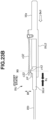
- Figs. 15A, 15B, and 15C are explanatory diagrams illustrating the catheter unit 100 and the base unit 200.
- Fig. 15A is a cross-sectional view illustrating the catheter unit 100.
- Fig. 15B is a perspective view illustrating a button 41.
- Fig. 15C is a perspective view illustrating the base unit 200.
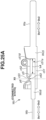
- Figs. 16A, 16B, and 16C are diagrams illustrating an operation that is performed by the operation unit 400.
- Fig. 16A is a diagram illustrating a state in which the operation unit 400 is at the detaching position.
- Fig. 16B is a diagram illustrating a state in which the operation unit 400 is at the release position.
- Fig. 16C is a diagram illustrating a state in which the operation unit 400 is at the fixing position.
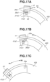
- Figs. 17A, 17B, and 17C are cross-sectional views illustrating an operation that is performed by the operation unit 400.
- Fig. 17A is a cross-sectional view illustrating a state in which the operation unit 400 is at the detaching position.
- Fig. 17B is a cross-sectional view illustrating a state in which the operation unit 400 is at the release position.
- Fig. 17C is a cross-sectional view illustrating a state in which the operation unit 400 is at the fixing position.
- the coupling unit 21c When the operation unit 400 is at the fixing position, the coupling unit 21c is in the lock state, and the held portion Wa of the drive wire W is fixed to a corresponding coupling unit 21c (refer to Fig. 14 ).
- the coupling unit 21c When the operation unit 400 is at the release position, the coupling unit 21c is in the release state, and the lock between the held portion Wa of the drive wire W and the coupling unit 21c is released (refer to Fig. 11 ). In this state, the connection between the drive wire W and the wire drive unit 300 is cut off. Accordingly, in a case where the catheter 11 receives external force, the bending portion 12 can be freely bent without receiving resistance generated by the wire drive unit 300.
- the catheter unit 100 When the operation unit 400 is at the detaching position, the catheter unit 100 can be detached from the base unit 200. In a state in which the operation unit 400 is at the detaching position, the catheter unit 100 can be attached to the base unit 200.
- the coupling unit 21c When the operation unit 400 is at the detaching position, the coupling unit 21c is in the release state, and the lock between the held portion Wa of the drive wire W and the coupling unit 21c is released (refer to Fig. 10 ).
- the catheter unit 100 includes an operation unit urging spring 43 that urges the operation unit 400, the button 41 serving as a movement member, and a button spring 42 that urges the button 41.
- the operation unit urging spring 43 is a compression spring.
- the operation unit 400 is urged by the operation unit urging spring 43 toward a direction Dh in which the operation unit 400 moves closer to the proximal end cover 16.
- the button 41 and the button spring 42 are included in the operation unit 400. In the movement of the operation unit 400 to the detaching position, the release position, and the fixing position, the button 41 and the button spring 42 move together with the operation unit 400.
- the button 41 is configured to be movable with respect to the operation unit 400 toward a direction intersecting with the direction of the rotational axis 400r of the operation unit 400.
- the button 41 is urged by the button spring 42 toward the outside of the catheter unit 100 (direction in which the button 41 moves away from the rotational axis 400r).
- the movement of the operation unit 400 from the release position to the detaching position is restricted by the button 41. Movement of the button 41 with respect to the operation unit 400 enables the operation unit 400 to be moved from the release position to the detaching position.
- the button 41 includes a button protrusion (restricted portion) 41a.
- the button protrusion 41a has an inclined surface 41a1 and a restricted surface 41a2.
- the base unit 200 includes the base frame 25.
- the base frame 25 includes the lock shaft 26.
- the lock shaft 26 includes the lock protrusion (restriction portion) 26a.
- a plurality of lock shafts 26 are disposed.
- the lock shafts 26 may each include the lock protrusion 26a, or some of the lock shafts 26 may each include the lock protrusion 26a.
- a lock groove 400a that engages with the lock shaft 26 is formed inside the operation unit 400.
- the lock groove 400a has a length in a direction different from the attaching/detaching direction DE.
- the lock groove 400a has a length in the rotational direction of the operation unit 400. It can also be said that the lock groove 400a has a length in a direction intersecting with (orthogonal to) the attaching/detaching direction DE.
- the lock grooves 400a are formed in such a manner as to respectively correspond to the plurality of lock shafts 26.
- the lock shaft 26 engages with the lock groove 400a via an inlet 400a1 of the lock groove 400a.
- the operation unit 400 is at the detaching position, and the coupling unit 21c is in the release state (refer to Fig. 10 ).
- the fixing of the first to ninth drive wires (W11 to W33) that are respectively fixed by the first to ninth coupling units (21c11 to 21c33) is released.
- the button protrusion 41a and the lock protrusion 26a face each other.
- the coupling unit 21c is in the release state (refer to Fig. 11 ). In this state, the fixing of the first to ninth drive wires (W11 to W33) that is respectively fixed by the first to ninth coupling units (21c11 to 21c33) is released.
- the operation unit 400 is allowed to be moved from the detaching position to the release position without an operation on the button 41. That is, in the movement of the operation unit 400 from the detaching position to the release position, the user needs not operate the button 41.
- the operation unit 400 moves to the fixing position.
- a positioning unit 400a2 of the lock groove 400a is at a position corresponding to the lock shaft 26.
- the operation unit 400 is urged by the operation unit urging spring 43 toward the direction Dh in which the operation unit 400 moves closer to the proximal end cover 16. Consequently, the positioning unit 400a2 engages with the lock shaft 26.
- the held portion Wa of the drive wire W is fixed to the coupling unit 21c as described above.
- the coupling unit 21c is in the lock state (refer to Fig. 14 ). Accordingly, the first to ninth drive wires (W11 to W33) are respectively fixed to the first to ninth coupling units (21c11 to 21c33). In this case, drive force can be transmitted from the wire drive unit 300 to the bending drive unit 13. That is, drive force is transmitted from the first to ninth drive sources (M11 to M33) to the first to ninth drive wires (W11 to W33) via the first to ninth coupling units (21c11 to 21c33), respectively.
- a wall 400a3 forming the lock groove 400a is on the upstream side of the lock shaft 26 in the detaching direction Dd of the catheter unit 100.
- the positioning unit 400a2 is on the upstream side of the lock shaft 26 in the detaching direction Dd. Consequently, when the operation unit 400 is at the release position, or when the operation unit 400 is at the fixing position, the detachment of the catheter unit 100 from the base unit 200 is restricted. Meanwhile, when the operation unit 400 is at the detaching position, the inlet 400a1 of the lock groove 400a is on the upstream side of the lock shaft 26 in the detaching direction Dd. Consequently, the catheter unit 100 is allowed to be detached from the base unit 200.
- the operation unit 400 In rotation of the operation unit 400 toward a release direction R2 in a state in which the operation unit 400 is at the fixing position, the operation unit 400 is moved at the release position. During the process of the movement of the operation unit 400 from the fixing position to the release position, as described above, the held portion Wa of the drive wire W is released from the coupling unit 21c.
- the coupling unit 21c When the operation unit 400 is moved to the detaching position, the coupling unit 21c enters the release state.
- load acting on the drive wire W for example, resistance to be received by the coupling unit 21c
- the coupling unit 21c can be reduced in detachment and attachment of the catheter unit 100 from and to the base unit 200.
- the user can easily attach or detached the catheter unit 100.
- the operation unit 400 When the operation unit 400 is moved to the release position, detachment of the catheter unit 100 from the base unit 200 is restricted, and the coupling unit 21c enters the release state. As described above, when the coupling unit 21c is in the release state, the connection between the drive wire W and the wire drive unit 300 is cut off, and the bending portion 12 can be freely bent without receiving resistance generated by the wire drive unit 300.
- the user can stop driving of the catheter 11 that is performed by the wire drive unit 300. Furthermore, since detachment of the catheter unit 100 from the base unit 200 is restricted, the user can pull out the catheter 11 from the inside of the target while holding the base unit 200.
- the movement of the operation unit 400 from the release position to the detaching position is restricted.
- the user is prevented from wrongly moving the operation unit 400 up to the detaching position when the user moves the operation unit 400 from the fixing position to the release position.
- the number of lock protrusions 26a is one, and the number of buttons 41 is one.
- the medical apparatus 1 may include a plurality of lock protrusions 26a and a plurality of buttons 41.
- Fig. 18A is a schematic diagram illustrating the drive wire W according to the present exemplary embodiment that includes the connection unit Wc.
- Fig. 18B is a perspective view illustrating a holder Wc1 and a rod Wc2 that are included in the connection unit Wc.
- Fig. 18C is a cross-sectional view illustrating the holder Wc1 and the rod Wc2 that are included in the connection unit Wc.
- Fig. 18A illustrates a state (connected state) in which the rod Wc2 is held in the holder Wc1
- Figs. 18B and 18C illustrate a state (cutoff state) in which the rod Wc2 is not held in the holder Wc1.
- connection unit Wc disposed in the drive wire W which is an arbitrary one of the first to ninth drive wires (W 11 to W33) included in the catheter unit 100 according to the present exemplary embodiment will be described.
- the connection unit Wc having substantially the same configuration as the configuration to be described below is disposed in each of the nine drive wires (W11 to W33).
- the connection unit Wc includes the holder Wc1 serving as a first member (engagement member, holding member) that is connected to the drive source M, and the rod Wc2 serving as a second member (engaged member, held member) that is connected to the wire member Wb of the drive wire W.
- a state of being connected to the drive source M and a state of being connected to the wire member Wb respectively indicate a state in which a corresponding member is disposed on an upstream side (drive source side) and a state in which a corresponding member is disposed on a downstream side (wire member side) on a drive transmission path from the drive source M to the wire member Wb, and do not require the corresponding members to be physically in direct contact.
- the holder Wc1 is a member formed integrally with the held portion Wa of the drive wire W.
- the holder Wc1 is connected to the drive source M via the held portion Wa and the coupling unit 21c ( Figs. 6A, 6B , and 6C ).
- the holder Wc1 and the held portion Wa may be formed as separate members.
- the rod Wc2 is fixed to a proximal end of the wire member Wb using an arbitrary fixing method, such as pressure bonding (swaging) or adhesive bonding.
- the holder Wc1 includes a cylindrical portion c11 that has a length in the direction Dc, and has a substantially bottomed cylindrical shape opened toward the direction Dc1.
- the cylindrical portion c11 is arranged adjacent to the held portion Wa in the direction Dc on the same axis, and the held portion Wa has a length in the direction Dc2 from a bottom portion of the cylindrical portion c11.
- the cylindrical portion c11 is an example of a tubular portion that has a length in the length direction of the wire member Wb and forms a space into which the second member can be inserted.
- the cylindrical portion c11 may have a polygonal tubular shape.
- the holder Wc1 includes a protruding portion c13 formed inside the cylindrical portion c11.
- the protruding portion c13 is formed in such a manner as to protrude from an inner surface of the cylindrical portion c11 toward an axis center.
- the protruding portion c13 is an example of a protruding portion protruding in a direction intersecting with the length direction (direction Dc) of the wire member Wb in the connection unit Wc.
- the protruding portion c13 When viewed in the direction Dc, the protruding portion c13 is disposed at a position that corresponds to a recess portion c23 in the rod Wc2 to be described below.
- the protruding portions c13 are disposed at two positions separated from each other by 180 degrees, in such a manner as to respectively correspond to the recess portions c23 disposed at two positions separated from each other by 180 degrees.
- an annular protruding portion c13 may be formed over the entire circumference of the inner surface of the cylindrical portion c11.
- the rod Wc2 includes a substantially columnar base portion c21 which has a length in the direction Dc2 from the proximal end of the wire member Wb, and two protruding pieces c22 protruding in the direction Dc2 from the base portion c21.
- the protruding pieces c22 each have a shape which is a part of a cylindrical shape having an outer diameter smaller than the base portion c21 and is of two parts divided from the cylindrical shape on a plane extending in the direction Dc. That is, the two protruding pieces c22 are two arcs disposed at positions opposed to each other on a common circumference, when viewed in the direction Dc2.
- the protruding pieces c22 mainly deform toward the direction Df which is a direction in which the two protruding pieces c22 are opposed to each other through the center of the common circumference. That is, the protruding piece c22 functions as a deformation element deformable in such a manner as to allow the protruding portion c13 to withdraw from the recess portion c23.
- the direction Df is a direction vertically intersecting with the length direction (direction Dc) of the wire member Wb in the connection unit Wc.
- the shape of the protruding pieces c22 is not limited to the above-described shape as long as the shape is a shape elastically deformable with moderate rigidity in the direction Df.
- the rod Wc2 includes the recess portion c23 on an outer surface of each of the protruding pieces c22.
- the recess portion c23 is formed between protrusions p1 and p2 protruding outward from the outer surface of the protruding piece c22.
- the protrusions p1 and p2 are arranged side by side in the direction Dc.
- the rod Wc2 is inserted in the direction Dc2 toward a space c11s inside the cylindrical portion c11 of the holder Wc1, and is attached to the holder Wc1 by being pressed in until the protruding portion c13 of the holder Wc1 fits into the recess portion c23 of the rod Wc2.
- the entire rod Wc2 i.e., portion from the base portion c21 to the protruding piece c22
- the recess portion c23 of the protruding piece c22 is disposed on the outer surface of the insertion portion to be inserted into the cylindrical portion c11.
- a state in which the rod Wc2 is held in the holder Wc1 in such a manner that drive force in the direction Dc1 or the direction Dc2 that has been transmitted from the drive source M can be transmitted to the wire member Wb will be referred to as a connected state (engaged state, attached state) of the connection unit Wc.
- a state in which the protruding portion c13 withdraws from the recess portion c23 and the connection between the drive source M and the wire member Wb is cut off will be referred to as a cutoff state (unconnected state, withdraw state, detachment state) of the connection unit Wc.
- Fig. 19A is a schematic diagram illustrating a cross-section of the connection unit Wc in the connected state.
- Fig. 19B is a schematic diagram illustrating a state of the connection unit Wc in a case where overload acts in a direction (direction Dc1) in which the wire member Wb is pressed.
- Fig. 19C is a schematic diagram illustrating a state of the connection unit Wc in a case where overload acts in a direction (direction Dc2) in which the wire member Wb is pulled.
- Fig. 19A is a schematic diagram illustrating a cross-section of the connection unit Wc in the connected state.
- Fig. 19B is a schematic diagram illustrating a state of the connection unit Wc in a case where overload acts in a direction (direction Dc1) in which the wire member Wb is pressed.
- Fig. 19C is a schematic diagram illustrating a state of the connection unit Wc in a case where overload acts in a direction (direction Dc2) in which the wire
- FIG. 20A is a schematic diagram illustrating movement of the catheter 11 in a case where the connection unit Wc is in the connected state.
- Fig. 20B is a schematic diagram illustrating movement of the catheter 11 in a case where overload acts in the direction (direction Dc1) in which the wire member Wb is pressed.
- Fig. 20C is a schematic diagram illustrating movement of the catheter 11 in a case where overload acts in the direction (direction Dc2) in which the wire member Wb is pulled.
- the catheter 11 is operated by pressing or pulling the wire member Wb.
- a configuration in which the catheter 11 is operated by just pulling the wire member Wb without pressing the wire member Wb is also conceivable.
- the number of actuators and the number of drive wires increase, which leads to upsizing of the medical apparatus 1 and also increase in the cost.
- a configuration in which the catheter 11 is operated by pressing or pulling the wire member Wb is employed.
- the protruding portion c13 of the holder Wc1 is fitted in the recess portion c23 of the rod Wc2. Specifically, the protruding portion c13 is held between the protrusions p1 and p2 in the direction Dc.
- a distance in the direction Df between the tops of the protrusions p1 and a distance in the direction Df between the tops of the protrusions p2 in a state in which the rod Wc2 is not attached to the holder Wc1 correspond to substantially the same distance, which is a distance Y2.
- This distance Y2 is longer than a distance Y1 in the direction Df between the protruding portions c13 of the holder Wc1 in a state in which the rod Wc2 is not attached to the holder Wc1.
- the protruding portions c13 of the holder Wc1 and a part (protrusions p1 and p2) of the rod Wc2 are in a positional relationship of interfering with each other in the direction Dc.
- connection unit Wc in a case where the connection unit Wc is in the connected state, the holder Wc1 and the rod Wc2 integrally move in the direction Dc1 and the direction Dc2.
- the plate spring 21ch of the coupling unit 21c moves the held portion Wa by drive force from the drive source M, which results in transmission of the drive force to the wire member Wb via the connection unit Wc.
- the bending portion 12 of the catheter 11 bends in such a manner that a side through which the wire member Wb is inserted becomes the outer side of bending.
- the bending portion 12 of the catheter 11 bends in such a manner that a side through which the wire member Wb is inserted becomes the outer side of bending.
- the protruding portion c13 of the holder Wc1 is desirably configured to fit into the recess portion c23 of the rod Wc2 in a backlash-reduced state.
- the protruding piece c22 on which the recess portion c23 is formed is made of elastic material, and because the protruding piece c22 is in a slightly-elastically-deformed state in the direction Df in the connected state, the protruding portion c13 is pressed against the protrusions p1 and p2 on both sides by the elastic force of the protruding piece c22.
- connection unit by a mechanism (snap-fit mechanism) that uses the deformation element (elastic element) made of elastic material, the holder Wc1 serving as the first member and the rod Wc2 serving as the second member are engaged with each other.
- force at a threshold value or less pulseling force at a first threshold value or less or compression force at a second threshold value or less, which will be described below
- the elastic force of the elastic element in a case where force at a threshold value or less (pulling force at a first threshold value or less or compression force at a second threshold value or less, which will be described below.
- the connection unit Wc allows the connection unit Wc to be assembled by a simple operation of inserting the rod Wc2 into the holder Wc1.
- the protrusions p1 and p2 of the rod Wc2 coming into contact with the protruding portion c13 of the holder Wc1 causes the protruding piece c22 to be in a slightly-bent state as compared with the state before the attachment of the rod Wc2 ( Fig. 18C ).
- a distance Y2' between the tops of the protrusions p1 in a state in which the rod Wc2 has been attached to the holder Wc1 is slightly smaller than the distance Y2 between the tops of the protrusions p1 in a state in which the rod Wc2 is not attached to the holder Wc1.
- connection unit Wc in the direction (direction Dc1) in which the wire member Wb is pressed will be described.
- compression force Fc acts between the holder Wc1 and the rod Wc2.
- the compression force Fc does not exceed a preset threshold value (second threshold value)
- the compression force Fc is received by the rod Wc2 via a contact portion between the protruding portion c13 of the holder Wc1 and the protrusion p2 of the rod Wc2. That is, the connection unit Wc according to the present exemplary embodiment is configured to maintain a state in which the protruding portion c13 is fitted in the recess portion c23, and transmit drive force from the drive source M to the wire member Wb, in a case where the compression force Fc at the second threshold value or less acts.
- connection unit Wc is configured to allow, in a case where the compression force Fc exceeding the second threshold value acts, the protruding portion c13 to come off from the recess portion c23, and cut off transmission of drive force from the drive source M to the wire member Wb ( Fig. 20B ).
- connection unit Wc from the connected state to the cutoff state when overload occurs prevents, even in a case where the holder Wc1 is driven in the direction Dc1 by excessively-large drive force due to malfunction of the drive source M, for example, the excessively-large drive force from being transmitted to the wire member Wb.
- the bending portion 12 of the catheter 11 can be prevented from being bent by excessively-strong force.
- connection unit Wc switches from the connected state to the cutoff state in accordance with the magnitude of the compression force Fc acting between the holder Wc1 and the rod Wc2. For this reason, also in a case where excessively-large external force is added to the wire member Wb by an object coming into contact with the catheter 11, the connection of the connection unit Wc is cut off. Even in a case where the proximal end of the wire member Wb is strongly pulled in the direction Dc1 by the wire member Wb receiving external force, a possibility that a member, such as the coupling unit 21c, is damaged can be reduced.
- a clearance Ld that allows relative movements of the holder Wc1 and the rod Wc2 is left between a leading end position in the direction Dc2 of the rod Wc2 in the connected state and a wall surface c118 of a bottom portion of the space c11s of the holder Wc1.
- the control unit 3 of the medical apparatus 1 may include a detection unit configured to detect that the connection of the connection unit Wc has been cut off, and stop the drive of each drive source M in a case where the cutoff of the connection of the connection unit Wc has been detected.
- connection unit Wc in the direction (direction Dc2) in which the wire member Wb is pulled
- pulling force Ft acts between the holder Wc1 and the rod Wc2.
- connection unit Wc from the connected state to the cutoff state when overload occurs prevents, even in a case where the holder Wc1 is driven in the direction Dc2 by excessively-large drive force due to malfunction of the drive source M, for example, the excessively-large drive force from being transmitted to the wire member Wb.
- the bending portion 12 of the catheter 11 can be prevented from being bent by excessively-strong force.
- connection unit Wc switches from the connected state to the cutoff state in accordance with the magnitude of the pulling force Ft acting between the holder Wc1 and the rod Wc2. For this reason, also in a case where excessively-large external force is added to the wire member Wb by an object coming into contact with the catheter 11, the connection of the connection unit Wc is cut off. With this configuration, even in a case where the proximal end of the wire member Wb is strongly pushed in the direction Dc2 due to the wire member Wb receiving external force, a possibility that a member, such as the coupling unit 21c, is damaged can be reduced.
- the threshold value (first threshold value) of the pulling force Ft is set to the same value as the threshold value (second threshold value) of the compression force Fc. This is a case for a configuration of cutting off, in a case where load exceeding a predetermined threshold value acts on the connection unit Wc, the connection between the drive source M and the wire member Wb irrespective the direction of the load.
- each member included in the connection unit Wc is a part of the catheter unit 100 that is a unit detachably attached to another unit (the base unit 200, etc.) of the medical apparatus 1.
- the catheter unit 100 is switched to the cutoff state due to load exceeding a threshold value acting on any connection unit Wc of the catheter unit 100, the catheter unit 100, the connection of which has been cut off, is detached, and a new catheter unit 100 can be attached. That is, the medical apparatus 1 is brought into a usable state again by a simple procedure of detaching the catheter unit 100 from the base unit 200 and replacing the catheter unit 100 with a new catheter unit 100.
- connection between the drive source M and the wire member Wb can be cut off in response to both overload in the direction in which the wire member Wb is pressed and overload in the direction in which the wire member Wb is pulled.
- An alternative configuration according to the present exemplary embodiment is that the connection between the drive source M and the wire member Wb is cut off by a combination of a detection element (strain gauge, etc.) and an electrically-controllable clutch (electromagnetic clutch, etc.) that releases the engagement of the clutch when overload is detected.
- a detection element strain gauge, etc.
- an electrically-controllable clutch electromagnettic clutch, etc.
- the apparatus is upsized and gets complicated because the detection element and the clutch are disposed.
- a simple configuration in which the protruding portion c13 comes off from the recess portion c23 when overload occurs is implemented, which realizes a function of cutting off the connection between the drive source M and the wire member Wb.
- Fig. 28A is a schematic diagram illustrating the drive wire W according to this modified example that includes the connection unit Wc.
- Fig. 28B is a perspective view illustrating the holder Wc1 and the rod Wc2 that are included in the connection unit Wc.
- Fig. 28C is a cross-sectional view illustrating the holder Wc1 and the rod Wc2 that are included in the connection unit Wc.
- Fig. 28A illustrates a state (connected state) in which the rod Wc2 is held in the holder Wc1
- Figs. 28B and 28C illustrate a state (unattached state) in which the rod Wc2 is not attached to the holder Wc1.
- Fig. 29 is a perspective view illustrating the drive wire W according to this modified example.
- the rod Wc2 is attached to the holder Wc1 in a state in which the pin c21a is fitted in the slit c11a.
- a configuration for attachment of the rod Wc2 including the pin c21a, to the holder Wc1 is, for example, that an elastic member, such as a coil spring, is disposed between a bottom portion of the pin 21a and the base portion c21, and the pin 21a is urged toward the leading end side (upside in Fig. 28C ).
- the pin c21a in insertion of the rod Wc2 into the cylindrical portion c11, the pin c21a is pushed in while the elastic member is compressed, whereby the pin c21a can be fitted into the slit c11a through an opening portion of the cylindrical portion c11.
- a fitting method is not limited to this.
- the pin c21a may be inserted from the outside of the cylindrical portion c11 via the slit c11a, and the pin c21a may be fixed using an adhesive agent or the like.
- a height Yp of the rod Wc2 in a direction vertically intersecting with the length direction (direction Dc) of the wire member Wb is more than an inner diameter Ys of the cylindrical portion c11 of the holder Wc1 within a range in which the slit c11a is formed.
- the pin c21a is configured not to come off from the slit c11a at least at the threshold value (first threshold value and second threshold value) of load at which the protruding portion c13 comes off from the recess portion c23.
- Fig. 30A is a schematic diagram illustrating a cross-section of the connection unit Wc in the connected state.
- Fig. 30B is a schematic diagram illustrating a state of the connection unit Wc in a case where overload acts in a direction (direction Dc1) in which the wire member Wb is pressed.
- Fig. 30C is a schematic diagram illustrating a state of the connection unit Wc in a case where overload acts in a direction (direction Dc2) in which the wire member Wb is pulled.
- the protruding portion c13 of the holder Wc1 is fitted in the recess portion c23 of the rod Wc2.
- the holder Wc1 and the rod Wc2 integrally move in the direction Dc1 and the direction Dc2.
- drive force from the drive source M is transmitted to the wire member Wb via the connection unit Wc.
- the pin c21a of the rod Wc2 is at a position between end portions on both sides of the slit c11a of the holder Wc1, and is not in contact with the end portions.
- the protruding portion c13 comes off from the recess portion c23, and the transmission of drive force from the drive source M to the wire member Wb is cut off (cutoff state).
- connection unit Wc Even in a case where the connection unit Wc has been switched to the cutoff state, the pin c21a remains in a state of being fitted in the slit c11a. For this reason, in the cutoff state of the connection unit Wc, the holder Wc1 and the rod Wc2 are in a linked state in a state in which relative movements of the holder Wc1 and the rod Wc2 are allowed within a range in which the pin c21a slides within the slit c11a.
- the above-described operation unit 400 is operated to detach the catheter unit 100 from the base unit 200.
- the link between the holder Wc1 and the rod Wc2 is still maintained, and thus in the detachment of the catheter unit 100, the holder Wc1 and the held portion Wa are detached together with the rod Wc2.
- the detachment of the catheter unit 100 in the direction Dc1 after the connection unit Wc has been switched to the cutoff state causes the holder Wc1 and the held portion Wa to be pulled out together with the rod Wc2 linked with the wire member Wb in a state in which the pin c21a is engaged with an end portion c11b on a side in the direction Dc1 of the slit c11a as illustrated in Fig. 30C .
- connection unit Wc is formed as a part of the catheter unit 100
- the first member can be prevented from being left behind within the base unit 200 when the catheter unit 100 is detached. This configuration makes a replacement operation of the catheter unit 10 easier, and the usability improves.
- the pin c21a described in this modified example is an example of a stopper (retainer unit, separation restriction unit) that restricts separation between the first member and the second member in the cutoff state of the connection unit Wc.
- the pin c21a is not limited to this configuration.
- a pin serving as a stopper may be disposed in the holder Wc1, and a slit that accepts the pin may be formed in the rod Wc2.
- the slit c11a is not limited to a through-hole and may have a groove shape.
- a configuration in which a plurality of sets of pins c21a and slits c11a is disposed may be employed.
- the stopper is not limited to a pin and is only required to have a shape that can restrict the separation between the first member and the second member.
- an annular protrusion portion like a snap ring may be used.
- connection unit Wc in which the protruding portion c13 is formed inside the holder Wc1 having a tubular shape, and the recess portions c23 are formed in the two protruding pieces c22 of the rod Wc2, another configuration that exerts a similar function may be employed.
- the modified example of the connection unit Wc is exemplified in Figs. 21A, 21B, 21C, 21D , 21E, 21F, and 21G .
- Fig. 21A is a schematic diagram schematically illustrating a connection configuration of the holder Wc1 and the rod Wc2 exemplified in the first exemplary embodiment.
- the protruding portion c13 formed on the holder Wc1 fits into the recess portion c23 formed in the rod Wc2, so that the holder Wc1 and the rod Wc2 are connected to each other and integrally move in the direction Dc.
- Fig. 21B illustrates a modified example in which the protruding portion c13 on the holder Wc1 is urged toward the recess portion c23 by an elastic member c131, such as a spring.
- an elastic member c131 such as a spring.
- change in a spring constant of the elastic member c131 and a deformation amount in the connected state can change the magnitude of load at which the protruding portion c13 comes off from the recess portion c23, i.e., a threshold value (first threshold value, second threshold value) of load at which the connection of the connection unit Wc is cut off.
- Fig. 21C illustrates a modified example in which a protruding portion c14 on the holder Wc1 is a spherical or cylindrical rotational member rotatably supported by a support portion of the holder Wc1.
- the influence of friction on a contact surface, which is generated when the protruding portion c13 comes off from the recess portion c23, is small.
- the magnitude of load at which the protruding portion c13 comes off from the recess portion c23 i.e., a threshold value (first threshold value, second threshold value) of load at which the connection of the connection unit Wc is cut off can be set more accurately.
- Fig. 21D illustrates a modified example in which the protruding portion c14 on the holder Wc1 is a rotational member, and the protruding portion c13 is urged toward the recess portion c23 by the elastic member c131 such as a spring.
- a threshold value (first threshold value, second threshold value) of load at which the connection of the connection unit Wc is cut off can be changed by a change in the elastic member c131, and the threshold value (first threshold value, second threshold value) of the load can be set more accurately.
- the recess portion c15 may be formed by two protrusions formed side by side in the direction Dc inside the cylindrical portion c11 of the holder Wc1 according to the first exemplary embodiment, and a protruding portion that fits into the recess portion may be formed on the protruding piece c22 of the rod Wc2. That is, in this case, similarly to the configurations illustrated in Figs. 21A to 21D , the holder Wc1 is formed integrally with the held portion Wa, and the rod Wc2 is attached to the proximal end of the wire member Wb.
- connection unit having a function similar to that in the first exemplary embodiment can be configured.
- the arrangement of the protruding portion and the recess portion can be swapped, and it is only required to be a configuration in which a protruding portion is arranged on either one of the first member and the second member, and a recess portion that fits with the protruding portion is arranged in the other one of the first member and the second member.
- Fig. 21F illustrates a modified example in which a protruding portion c16 and a protruding portion c17 are formed on a first member Wc1" at different positions, and a protruding portion c26 and a protruding portion c27 are formed on a second member Wc2" at different positions.
- a member on which the protruding portions c16 and c17 are formed in place of the protruding portion c13 in the holder Wc1 according to the first exemplary embodiment is formed integrally with the held portion Wa as the first member Wc1", for example.
- a member on which the protruding portions c26 and c27 are formed in place of the protrusions p1 and p2 in the rod Wc2 according to the first exemplary embodiment is formed at the proximal end of the wire member Wb as the second member Wc2', whereby the configuration can be implemented.
- the first member Wc1' and the held portion Wa may be separate members.
- the first protruding portion and the second protruding portion in place of the "protruding portion" of the first member are formed, and the third protruding portion and the fourth protruding portion in place of the "recess portion" of the second member are formed, whereby a function similar to the combination of the protruding portion and the recess portion can be obtained.
- connection unit Wc is formed by the protruding portion and the recess portion fitting with each other.
- the configuration is not limited to this configuration, and as exemplified in this modified example and the following modified example illustrated in Fig. 21F , the connection unit Wc may be formed by protruding portions and protruding portions engaging with each other at two different positions.
- the connection unit Wc does not depend on a specific shape of the first member and the second member, and it is sufficient that a shape formed on the first member and a shape formed on the second member are engaged in such a manner as to restrict relative movements in the direction Dc1 and the direction Dc2 of the first member and the second member.
- 21G illustrates a modified example in which a protruding portion c18 and a protruding portion c19 are formed on the first member Wc1" at different positions, and the protruding portion c28 and the protruding portion c29 are formed on the second member Wc2" at different positions.
- the protruding portion c18 is an example of the first protruding portion
- the protruding portion c19 is an example of the second protruding portion
- the protruding portion c28 is an example of the third protruding portion that engages with the first protruding portion
- the protruding portion c29 is an example of the fourth protruding portion that engages with the second protruding portion.
- Figs. 21F and 21G illustrate the configuration in which the first member Wc1" and the second member Wc2" are engaged with each other at two positions. Needless to say, the first member Wc1" and the second member Wc2" may be engaged with each other at three or more positions.
- the shape of the protruding portions is also not limited.
- an elastic member such as a spring, as illustrated in Figs. 21B and 21D may be attached to a protruding portion.
- a medical apparatus will be described with reference to Figs. 22A , 22B , 22C , 23A , 23B , and 23C .
- the present exemplary embodiment differs from the first exemplary embodiment in a configuration of a connection unit Wc that connects the drive source M and the wire member Wb.
- the components assigned the same reference numerals as those in the first exemplary embodiment have substantially the same configuration and function as those described in the first exemplary embodiment, and a difference from the first exemplary embodiment will be mainly described.
- connection unit Wc disposed in the drive wire W which is an arbitrary one of the first to ninth drive wires (W 11 to W33) included in the catheter unit 100 according to the present exemplary embodiment, will be described.
- the connection unit Wc having substantially the same configuration as the configuration to be described below is disposed in each of the nine drive wires (W11 to W33).
- the connection unit Wc includes the holder Wc3 serving as a first member (engagement member, holding member) that is connected to the drive source M, and the rod Wc4 serving as a second member (engaged member, held member) that is connected to the wire member Wb of the drive wire W.
- the holder Wc3 is a member formed integrally with the held portion Wa of the drive wire W. Accordingly, the holder Wc3 is connected to the drive source M via the held portion Wa and the coupling unit 21c ( Figs. 6A, 6B , and 6C ).
- the holder Wc3 and the held portion Wa may be formed as separate members.
- the rod Wc4 is fixed to the proximal end of the wire member Wb using an arbitrary fixing method, such as pressure bonding (swaging) or adhesive bonding.
- the holder Wc3 includes a main body portion (base portion) c31 formed integrally with the held portion Wa, and a plate spring c32 attached to the main body portion c31 using a fixing unit, such as a screw c321.
- the main body portion c31 has a groove shape formed with a bottom portion c311 and side wall portions c312 and has a cross-sectional shape resembling a U-shape with right-angled corners (rectangular shape with one side opened) when viewed in the direction Dc.
- the plate spring c32 In a case where the plate spring c32 receives external force, the plate spring c32 mainly deforms in the direction Df. That is, the plate spring c32 functions as a deformation element deformable in such a manner as to allow the protruding portion c33 to come off from a recess portion c43 to be described below.
- the rod Wc4 includes a base portion c41 that has a substantially quadrangular prism shape and has a length in the direction Dc2 from the proximal end of the wire member Wb, and the recess portion c43 formed on a side surface (surface facing the plate spring c32) in the direction Df of the base portion c41.
- the recess portion c43 is formed between protrusions p3 and p4 protruding in the direction Df from the base portion c41.
- the protrusions p3 and p4 are formed side by side in the direction Dc.
- the rod Wc4 is inserted in the direction Dc2 toward the space c31s between the main body portion c31 and the plate spring c32 of the holder Wc3 and is attached to the holder Wc3 by being pressed in until the protruding portion c33 of the holder Wc3 fits into the recess portion c43 of the rod Wc4.
- a part of the rod Wc4 in the direction Dc2 is an insertion portion that is inserted into the space c31s in the holder Wc3.
- the protruding portion c33 of the holder Wc3 is desirably configured to fit into the recess portion c43 of the rod Wc4 in a backlash-reduced state.
- the protruding portion 33 is formed at the leading end portion of the plate spring c32 having elasticity, and by the elastic force of the plate spring c32 due to the plate spring c32 slightly-elastically-deformed in the direction Df (upward in Fig. 23A ) in the connected state, the protruding portion c33 is pressed against the protrusions p3 and p4 on both sides.
- connection unit Wc connects the holder Wc3 serving as the first member and the rod Wc4 serving as the second member.
- the compression force Fc does not exceed a preset threshold value (second threshold value)
- the compression force Fc is received by the rod Wc4 via a contact portion between the protruding portion c33 of the holder Wc3 and the protrusion p4 of the rod Wc4. That is, the connection unit Wc according to the present exemplary embodiment is configured to maintain, in a case where the compression force Fc at the second threshold value or less acts, a state in which the protruding portion c33 is fitted in the recess portion c43, and transmit drive force from the drive source M to the wire member Wb.
- a preset threshold value second threshold value
- the plate spring c32 elastically deforms in such a manner that the protruding portion c33 moves over the protrusion p4 of the rod Wc4. Consequently, the holder Wc3 and the rod Wc4 move relative to each other while the protruding portion c33 moves over the protrusion p4, and the protruding portion c33 comes off from the recess portion c43. In a state (cutoff state) in which the protruding portion c33 has come off from the recess portion c43, even in a case where the holder Wc3 moves in the direction Dc1, the rod Wc4 does not move in the direction Dc1.
- connection unit Wc is configured to allow, in a case where the compression force Fc exceeding the second threshold value acts, the protruding portion c33 to come off from the recess portion c43, and cut off the transmission of drive force from the drive source M to the wire member Wb ( Fig. 23B ).
- a clearance Ld that allows relative movements of the holder Wc3 and the rod Wc4 is left between a leading end position in the direction Dc2 of the rod Wc4 in the connected state and a wall surface c318 serving as a bottom portion of the space c31s of the holder Wc3.
- the length in the direction Dc of the clearance Ld is set in such a manner that the wall surface c318 does not come into contact with the rod Wc4 even in a case where the holder Wc3 further moves in the direction Dc1 by a predetermined distance after the protruding portion c33 has completely come off from the recess portion c43, with respect to a position X0 of the protruding portion c33 in the connected state.
- a clearance Ld With a clearance Ld, drive force in the direction Dc1 is prevented from being transmitted by the rod Wc4 being pressed by the wall surface c318 of the holder Wc3 although the protruding portion c33 has come off from the recess portion c43.
- connection unit Wc in the direction (direction Dc2) in which the wire member Wb is pulled
- pulling force Ft acts between the holder Wc3 and the rod Wc4.
- the plate spring c32 elastically deforms in such a manner that the protruding portion c33 moves over the protrusion p3 of the rod Wc4. Consequently, the holder Wc3 and the rod Wc4 move relative to each other while the protruding portion c33 moves over the protrusion p3, and the protruding portion c33 comes off from the recess portion c43. In a state (cutoff state) in which the protruding portion c33 has come off from the recess portion c43, even in a case where the holder Wc3 moves in the direction Dc2, the rod Wc4 does not move in the direction Dc2.
- connection unit Wc The switching of the state of the connection unit Wc from the connected state to the cutoff state when overload occurs reduces a possibility that a member, such as the coupling unit 21c, is damaged when the bending portion 12 of the catheter 11 is bent by excessively-strong force due to the malfunction of the drive source M, or the wire member Wb receives external force.
- the connection unit Wc includes the holder Wc5 serving as a first member (engagement member, holding member) that is connected to the drive source M, and the rod Wc6 serving as a second member (engaged member, held member) that is connected to the wire member Wb of the drive wire W.
- the holder Wc5 is a member formed integrally with the held portion Wa of the drive wire W.
- the holder Wc5 is connected to the drive source M via the held portion Wa and the coupling unit 21c ( Figs. 6A, 6B , and 6C ).
- the holder Wc5 and the held portion Wa may be formed as separate members.
- the rod Wc6 is fixed to the proximal end of the wire member Wb using an arbitrary fixing method, such as pressure bonding (swaging) or adhesive bonding.
- the holder Wc5 includes a main body portion (base portion) c51 formed integrally with the held portion Wa, and a torsion spring (torsion coil spring) c52 supported by the main body portion c31.
- the main body portion c51 has a groove shape formed with a bottom portion c511 and side wall portions c512 and has a cross-sectional shape resembling a U-shape with right-angled corners (rectangular shape with one side opened) when viewed in the direction Dc.
- the torsion spring c52 is attached to an opened portion in the Df direction of the main body portion c51.
- the torsion spring c52 includes a coil portion c521 supported by a shaft portion c513 attached to the main body portion c51, an arm portion c522 lengthened from the coil portion c521 in the direction Dc1, and an arm portion c523 extending from the coil portion c521 in the direction Dc2.
- the arm portion c522 on a side in the direction Dc1 is a free end that is supported by a support portion 514 of the main body portion c51, and is elastically-deformable in such a manner as to move away from the support portion 514 by being pressed by the rod Wc6.
- the protruding portion c53 is only required to be formed at a position at which the protruding portion c53 can engage with the recess portion c63, and thus, for example, a plurality of torsion springs c52 each including the protruding portion c53 may be formed, and a plurality of recess portions c63 corresponding thereto may be formed in the rod Wc6.
- Fig. 25A is a schematic diagram illustrating a cross-section of the connection unit Wc in the connected state.
- Fig. 25C is a schematic diagram illustrating a state of the connection unit Wc in a case where overload acts in a direction (direction Dc1) in which the wire member Wb is pressed.
- Fig. 25C is a schematic diagram illustrating a state of the connection unit Wc in a case where overload acts in a direction (direction Dc2) in which the wire member Wb is pulled.
- connection unit Wc connects the holder Wc5 serving as the first member and the rod Wc6 serving as the second member to each other, by a mechanism (snap-fit mechanism) that uses a deformation element made of elastic material.
- connection unit Wc in the direction (direction Dc1) in which the wire member Wb is pressed
- compression force Fc acts between the holder Wc5 and the rod Wc6.
- the compression force Fc does not exceed a preset threshold value (second threshold value)
- the compression force Fc is received by the rod Wc6 via a contact portion between the protruding portion c53 of the holder Wc5 and the protrusion p6 of the rod Wc6. That is, the connection unit Wc according to the present exemplary embodiment is configured to maintain, in a case where the compression force Fc at the second threshold value or less acts, a state in which the protruding portion c53 is fitted in the recess portion c63, and drive force from the drive source M is transmitted to the wire member Wb.
- the torsion spring c52 elastically deforms in such a manner that the protruding portion c53 moves over the protrusion p6 of the rod Wc6. Consequently, the holder Wc5 and the rod Wc6 move relative to each other while the protruding portion c53 moves over the protrusion p6, and the protruding portion c53 comes off from the recess portion c63.
- connection unit Wc is configured to allow, in a case where the compression force Fc exceeding the second threshold value acts, the protruding portion c53 to come off from the recess portion c63 and cut off transmission of drive force from the drive source M to the wire member Wb ( Fig. 25B ).
- the torsion spring c52 elastically deforms in such a manner that the protruding portion c53 moves over the protrusion p5 of the rod Wc6. Consequently, the holder Wc5 and the rod Wc6 move relative to each other while the protruding portion c53 moves over the protrusion p5, and the protruding portion c53 comes off from the recess portion c63.
- the rod Wc8 includes a base portion c81 that has a substantially quadrangular prism shape and has a length in the direction Dc2 from the proximal end of the wire member Wb, and the recess portion c83 formed on a side surface (surface facing the rotational member c730) in the direction Df of the base portion c81.
- the recess portion c83 is formed between protrusions p7 and p8 protruding in the direction Df from the base portion c81.
- the protrusions p7 and p8 are arranged side by side in the direction Dc.
- the connection unit Wc includes the holder Wc9 serving as a first member (engagement member, holding member) that is connected to the drive source M, and the rod Wc10 serving as a second member (engaged member, held member) that is connected to the wire member Wb of the drive wire W.
- the holder Wc9 is a member formed integrally with the held portion Wa of the drive wire W.
- the holder Wc9 is connected to the drive source M via the held portion Wa and the coupling unit 21c ( Figs. 6A, 6B , and 6C ).
- the holder Wc9 and the held portion Wa may be formed as separate members.
- the rod Wc10 is fixed to the proximal end of the wire member Wb by using an arbitrary fixing method, such as pressure bonding (swaging) or adhesive bonding.
- the iron plate c101 is pivotably supported by the first shaft portion c103 and pulled by the magnet c100 in the direction Dc2.
- the iron plate c101 is in close contact with an end surface in the direction Dc1 of the magnet c100, and an end surface c91a1 in the direction Dc1 of the main body cylindrical portion c91.
- the iron plate c102 is pivotably supported by the second shaft portion c104 and pulled by the magnet c100 in the direction Dc1.
- the iron plate c102 is in close contact with an end surface in the direction Dc2 of the magnet c100, and an end surface c91a2 in the direction Dc2 of the main body cylindrical portion c91.
- a state in which the rod Wc10 is held in the holder Wc9 in such a manner that drive force in the direction Dc1 or the direction Dc2 that has been transmitted from the drive source M can be transmitted to the wire member Wb will be referred to as a connected state (engaged state, attached state) of the connection unit Wc.
- a state in which either the iron plate c101 or c102 comes off from the magnet c100 and the connection between the drive source M and the wire member Wb is cut off will be referred to as a cutoff state (unconnected state, withdraw state, detachment state) of the connection unit Wc.
- Fig. 33A is a schematic diagram illustrating a cross-section of the connection unit Wc in the connected state.
- Fig. 33B is a schematic diagram illustrating a state of the connection unit Wc in a case where overload acts in a direction (direction Dc1) in which the wire member Wb is pressed.
- Fig. 33C is a schematic diagram illustrating a state of the connection unit Wc in a case where overload acts in a direction (direction Dc2) in which the wire member Wb is pulled.
- the length in the direction Dc of the clearance Ld is set in such a manner that the wall surface c928 does not come into contact with the rod Wc10 even in a case where the holder Wc9 further moves in the direction Dc1 by a predetermined distance after the iron plate c101 has been completely separated from the magnet c100, with respect to a position X0 of the iron plate c101 in the connected state.
- drive force in the direction Dc1 is prevented from being transmitted by the rod Wc10 being pressed by the wall surface c928 of the holder Wc9 even though the iron plate c101 has come off from the magnet c100.
- connection unit Wc in the direction (direction Dc2) in which the wire member Wb is pulled
- pulling force Ft acts between the holder Wc9 and the rod Wc10.
- connection unit Wc is configured to maintain, in a case where the pulling force Ft at the first threshold value or less acts, a state in which the end surface c91a2 of the main body cylindrical portion c91 and the iron plate c102 are in close contact with each other, and transmit drive force from the drive source M to the wire member Wb.
- connection unit Wc The switching of the state of the connection unit Wc from the connected state to the cutoff state when overload occurs reduces a possibility that a member, such as the coupling unit 21c, is damaged when the bending portion 12 of the catheter 11 is bent by excessively-strong force due to the malfunction of the drive source M, or the wire member Wb receives external force.
- each member included in the connection unit Wc is a part of the catheter unit 100 that is a unit detachably attached to another unit (the base unit 200, etc.) of the medical apparatus 1.
- the medical apparatus 1 can be brought into a usable state again by a simple method of detaching the catheter unit 100 from the base unit 200 after cutting off the connection between the drive source M and the wire member Wb, and replacing the catheter unit 100 with a new catheter unit 100.
- the first threshold value and the second threshold value may be set to different values. For example, in a case where load expected in a normal use condition varies depending on the direction in which the wire member Wb is driven, the first threshold value and the second threshold value are set in accordance with the range of the expected load.
- common values are set for the first threshold value and the second threshold value in the connection units among sets of the plurality of drive sources (M11 to M33) and the plurality of wire members (Wb11 to Wb33).
- different values of the first threshold value and the second threshold value may be set in the connection units among sets of drive sources and wire members. For example, in a case where expected load varies between a wire member connected to a guide ring closer to the leading end and a wire member connected to a guide ring closer to the proximal end in the bending portion 12 of the catheter 11, the first threshold value and the second threshold value are set in accordance with the range of the expected load.
- drive sources and wire members are connected via connection units in the sets of the plurality of drive sources (M11 to M33) and the plurality of wire members (Wb11 to Wb33).
- a connection unit may be disposed in only a part of all sets including the drive sources and the wire members.
- the target is not limited to this, and the target to be operated may include a multi-joint robot.
- the multi-joint robot include a medical robot arm including a surgical appliance (forceps, sharp pointed scalpel, etc.) at its leading end, for example.
- a surgical appliance forceps, sharp pointed scalpel, etc.
- the breakaway mechanism described in each of the above-described exemplary embodiments may be applied.
Landscapes
- Health & Medical Sciences (AREA)
- Life Sciences & Earth Sciences (AREA)
- Surgery (AREA)
- Engineering & Computer Science (AREA)
- Public Health (AREA)
- Animal Behavior & Ethology (AREA)
- Biomedical Technology (AREA)
- Heart & Thoracic Surgery (AREA)
- Veterinary Medicine (AREA)
- General Health & Medical Sciences (AREA)
- Molecular Biology (AREA)
- Nuclear Medicine, Radiotherapy & Molecular Imaging (AREA)
- Medical Informatics (AREA)
- Biophysics (AREA)
- Pathology (AREA)
- Physics & Mathematics (AREA)
- Optics & Photonics (AREA)
- Radiology & Medical Imaging (AREA)
- Robotics (AREA)
- Pulmonology (AREA)
- Anesthesiology (AREA)
- Hematology (AREA)
- Media Introduction/Drainage Providing Device (AREA)
- Endoscopes (AREA)
Applications Claiming Priority (2)
| Application Number | Priority Date | Filing Date | Title |
|---|---|---|---|
| JP2021141376A JP7731733B2 (ja) | 2021-08-31 | 2021-08-31 | 医療装置 |
| PCT/JP2022/030177 WO2023032599A1 (ja) | 2021-08-31 | 2022-08-05 | 医療装置 |
Publications (2)
| Publication Number | Publication Date |
|---|---|
| EP4397352A1 true EP4397352A1 (de) | 2024-07-10 |
| EP4397352A4 EP4397352A4 (de) | 2025-08-13 |
Family
ID=85412192
Family Applications (1)
| Application Number | Title | Priority Date | Filing Date |
|---|---|---|---|
| EP22864185.8A Pending EP4397352A4 (de) | 2021-08-31 | 2022-08-05 | Medizinische vorrichtung |
Country Status (5)
| Country | Link |
|---|---|
| US (1) | US20240189048A1 (de) |
| EP (1) | EP4397352A4 (de) |
| JP (1) | JP7731733B2 (de) |
| CN (1) | CN117881453A (de) |
| WO (1) | WO2023032599A1 (de) |
Families Citing this family (1)
| Publication number | Priority date | Publication date | Assignee | Title |
|---|---|---|---|---|
| CN121370349A (zh) * | 2025-12-23 | 2026-01-23 | 上海魅丽纬叶医疗科技股份公司 | 一种手柄及消融导管 |
Family Cites Families (17)
| Publication number | Priority date | Publication date | Assignee | Title |
|---|---|---|---|---|
| JPH03111024A (ja) * | 1989-09-26 | 1991-05-10 | Olympus Optical Co Ltd | 内視鏡 |
| JP4043081B2 (ja) * | 1997-10-14 | 2008-02-06 | オリンパス株式会社 | 内視鏡の湾曲機構 |
| JPH11253390A (ja) * | 1998-03-16 | 1999-09-21 | Olympus Optical Co Ltd | 内視鏡 |
| US8888688B2 (en) * | 2000-04-03 | 2014-11-18 | Intuitive Surgical Operations, Inc. | Connector device for a controllable instrument |
| JP5931497B2 (ja) * | 2011-08-04 | 2016-06-08 | オリンパス株式会社 | 手術支援装置およびその組立方法 |
| JP6157063B2 (ja) * | 2012-05-31 | 2017-07-05 | キヤノン株式会社 | 医療器具 |
| JP6025401B2 (ja) | 2012-05-31 | 2016-11-16 | キヤノン株式会社 | 医療器具 |
| US9107573B2 (en) * | 2012-10-17 | 2015-08-18 | Karl Storz Endovision, Inc. | Detachable shaft flexible endoscope |
| JP2020121162A (ja) * | 2015-03-06 | 2020-08-13 | エシコン エルエルシーEthicon LLC | 測定の安定性要素、クリープ要素、及び粘弾性要素を決定するためのセンサデータの時間依存性評価 |
| DE202015106167U1 (de) * | 2015-11-13 | 2017-02-16 | BANDELIN patent GmbH & Co. KG | Bewegungsvorrichtung sowie System zur Reinigung von medizinischen Instrumenten |
| US11369443B2 (en) * | 2019-06-27 | 2022-06-28 | Cilag Gmbh International | Method of using a surgical modular robotic assembly |
| US11730349B2 (en) * | 2019-10-25 | 2023-08-22 | Canon U.S.A., Inc. | Steerable medical device with bending sections and improved connector therefor |
| JP2021141376A (ja) | 2020-03-03 | 2021-09-16 | 京セラドキュメントソリューションズ株式会社 | 画像読取装置 |
| US12076505B2 (en) * | 2020-08-06 | 2024-09-03 | Canon U.S.A., Inc. | Magnetic connector for steerable medical device |
| EP4225162A1 (de) * | 2020-10-08 | 2023-08-16 | Conmed Corporation | Vorrichtungen und verfahren zum anbringen einer hämostatischen klammeranordnung |
| US12471982B2 (en) * | 2020-12-02 | 2025-11-18 | Cilag Gmbh International | Method for tissue treatment by surgical instrument |
| JP7731735B2 (ja) * | 2021-08-31 | 2025-09-01 | キヤノン株式会社 | 医療装置 |
-
2021
- 2021-08-31 JP JP2021141376A patent/JP7731733B2/ja active Active
-
2022
- 2022-08-05 WO PCT/JP2022/030177 patent/WO2023032599A1/ja not_active Ceased
- 2022-08-05 EP EP22864185.8A patent/EP4397352A4/de active Pending
- 2022-08-05 CN CN202280059119.9A patent/CN117881453A/zh active Pending
-
2024
- 2024-02-26 US US18/587,295 patent/US20240189048A1/en active Pending
Also Published As
| Publication number | Publication date |
|---|---|
| EP4397352A4 (de) | 2025-08-13 |
| JP7731733B2 (ja) | 2025-09-01 |
| JP2023034902A (ja) | 2023-03-13 |
| CN117881453A (zh) | 2024-04-12 |
| US20240189048A1 (en) | 2024-06-13 |
| WO2023032599A1 (ja) | 2023-03-09 |
Similar Documents
| Publication | Publication Date | Title |
|---|---|---|
| EP4397352A1 (de) | Medizinische vorrichtung | |
| CN107666877B (zh) | 手术器械外壳及相关的系统和方法 | |
| US7758389B2 (en) | Connector assembly having a movable plug | |
| KR101904503B1 (ko) | 광섬유 커넥터용 듀플렉스 클립 조립체 | |
| US7645162B2 (en) | Connector assembly having a slider element | |
| EP4410352A1 (de) | Medizinische vorrichtung | |
| JP2005501289A (ja) | ユニバーサルアダプタ | |
| EP1849398A2 (de) | Endoskopkupplung, Kabelausgang und Endoskopvorrichtung | |
| WO2018213514A2 (en) | Optical connector with forward-biasing projections | |
| CA2641787C (en) | Optical connector assembling jig | |
| JP7731735B2 (ja) | 医療装置 | |
| US20240350771A1 (en) | Medical system | |
| JP2012070933A (ja) | 着脱機構、及び術具システム | |
| JP7589057B2 (ja) | 医療装置および湾曲可能ユニット | |
| WO2022163470A1 (ja) | 医療装置および湾曲可能ユニット | |
| US20240416080A1 (en) | Medical device and bendable unit | |
| US20240408354A1 (en) | Medical apparatus | |
| JP5897394B2 (ja) | フレキシブルセンサ | |
| GB2415996A (en) | Medical instrument with two-part coupling | |
| JPH03111024A (ja) | 内視鏡 | |
| JP6495111B2 (ja) | フレキシブルセンサ | |
| WO2023153167A1 (ja) | 連続体ロボット | |
| JP5925580B2 (ja) | フレキシブルセンサ | |
| US20240382274A1 (en) | Continuum robot and information processing apparatus | |
| JP3248076U (ja) | 内視鏡 |
Legal Events
| Date | Code | Title | Description |
|---|---|---|---|
| STAA | Information on the status of an ep patent application or granted ep patent |
Free format text: STATUS: THE INTERNATIONAL PUBLICATION HAS BEEN MADE |
|
| PUAI | Public reference made under article 153(3) epc to a published international application that has entered the european phase |
Free format text: ORIGINAL CODE: 0009012 |
|
| STAA | Information on the status of an ep patent application or granted ep patent |
Free format text: STATUS: REQUEST FOR EXAMINATION WAS MADE |
|
| 17P | Request for examination filed |
Effective date: 20240331 |
|
| AK | Designated contracting states |
Kind code of ref document: A1 Designated state(s): AL AT BE BG CH CY CZ DE DK EE ES FI FR GB GR HR HU IE IS IT LI LT LU LV MC MK MT NL NO PL PT RO RS SE SI SK SM TR |
|
| DAV | Request for validation of the european patent (deleted) | ||
| DAX | Request for extension of the european patent (deleted) | ||
| REG | Reference to a national code |
Ref country code: DE Ref legal event code: R079 Free format text: PREVIOUS MAIN CLASS: A61M0025092000 Ipc: A61B0001000000 |
|
| A4 | Supplementary search report drawn up and despatched |
Effective date: 20250714 |
|
| RIC1 | Information provided on ipc code assigned before grant |
Ipc: A61B 1/00 20060101AFI20250708BHEP Ipc: A61B 1/01 20060101ALI20250708BHEP Ipc: A61M 25/092 20060101ALI20250708BHEP Ipc: A61B 1/005 20060101ALN20250708BHEP Ipc: A61B 1/267 20060101ALN20250708BHEP |