EP4397253A1 - Klammerinstrument - Google Patents
Klammerinstrument Download PDFInfo
- Publication number
- EP4397253A1 EP4397253A1 EP22869378.4A EP22869378A EP4397253A1 EP 4397253 A1 EP4397253 A1 EP 4397253A1 EP 22869378 A EP22869378 A EP 22869378A EP 4397253 A1 EP4397253 A1 EP 4397253A1
- Authority
- EP
- European Patent Office
- Prior art keywords
- clipping
- clip
- distal end
- mating
- proximal end
- Prior art date
- Legal status (The legal status is an assumption and is not a legal conclusion. Google has not performed a legal analysis and makes no representation as to the accuracy of the status listed.)
- Pending
Links
Images


Classifications
-
- A—HUMAN NECESSITIES
- A61—MEDICAL OR VETERINARY SCIENCE; HYGIENE
- A61B—DIAGNOSIS; SURGERY; IDENTIFICATION
- A61B17/00—Surgical instruments, devices or methods
- A61B17/10—Surgical instruments, devices or methods for applying or removing wound clamps, e.g. containing only one clamp or staple; Wound clamp magazines
-
- A—HUMAN NECESSITIES
- A61—MEDICAL OR VETERINARY SCIENCE; HYGIENE
- A61B—DIAGNOSIS; SURGERY; IDENTIFICATION
- A61B17/00—Surgical instruments, devices or methods
- A61B17/12—Surgical instruments, devices or methods for ligaturing or otherwise compressing tubular parts of the body, e.g. blood vessels or umbilical cord
- A61B17/128—Surgical instruments, devices or methods for ligaturing or otherwise compressing tubular parts of the body, e.g. blood vessels or umbilical cord for applying or removing clamps or clips
- A61B17/1285—Surgical instruments, devices or methods for ligaturing or otherwise compressing tubular parts of the body, e.g. blood vessels or umbilical cord for applying or removing clamps or clips for minimally invasive surgery
-
- A—HUMAN NECESSITIES
- A61—MEDICAL OR VETERINARY SCIENCE; HYGIENE
- A61B—DIAGNOSIS; SURGERY; IDENTIFICATION
- A61B17/00—Surgical instruments, devices or methods
- A61B17/08—Wound clamps or clips, i.e. not or only partly penetrating the tissue ; Devices for bringing together the edges of a wound
- A61B17/083—Clips, e.g. resilient
-
- A—HUMAN NECESSITIES
- A61—MEDICAL OR VETERINARY SCIENCE; HYGIENE
- A61B—DIAGNOSIS; SURGERY; IDENTIFICATION
- A61B17/00—Surgical instruments, devices or methods
- A61B2017/0046—Surgical instruments, devices or methods with a releasable handle; with handle and operating part separable
- A61B2017/00473—Distal part, e.g. tip or head
-
- A—HUMAN NECESSITIES
- A61—MEDICAL OR VETERINARY SCIENCE; HYGIENE
- A61B—DIAGNOSIS; SURGERY; IDENTIFICATION
- A61B90/00—Instruments, implements or accessories specially adapted for surgery or diagnosis and not covered by any of the groups A61B1/00 - A61B50/00, e.g. for luxation treatment or for protecting wound edges
- A61B90/03—Automatic limiting or abutting means, e.g. for safety
- A61B2090/037—Automatic limiting or abutting means, e.g. for safety with a frangible part, e.g. by reduced diameter
Definitions
- Axial direction and "radial direction” in the embodiment of the present disclosure may indicate directions, where the "radial direction” is perpendicular to the "axial direction”, or the "axial direction” is a direction in which the passage of the sheath pipe 210 extends, and the "radial direction” is a direction perpendicular to the direction in which the passage of the sheath pipe 210 extends.
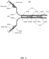
- the at least two clip devices 300 may further include the extension portion 400, and the extension portion 400 may be connected to the at least two clipping portions 310.
- a proximal end of the extension portion 400 may be connected to the core shaft 220 (not shown in FIG. 4 ), and a distal end of the extension portion 400 may be switchably connected to one of the clipping portions 310.
- the "switchably connected" may be that a release of the connection between a distal end of the extension portion 400 and one of the clipping portions 310 is achieved and then the distal end of the extension portion 400 is switched to connecting to one of the rest of the clipping portions 310.
- the core shaft 220 may be of a split structure with the extension portion 400, and the distal end of the core shaft 220 may be fixedly connected to the proximal end of the extension portion 400 through snap-fit, welding, etc.
- the core shaft 220 may be of a one-piece structure with the extension portion 400, and the distal end of the core shaft 220 may extend to form the extension portion 400.
- the total length of the at least two clip devices 300 when connected to each other may be less than a sum of a length of each of the at least two clip devices 300.
- the clip devices 300 may include the clipping portions 310 and the extension portion 400.
- the length of each of the clip devices 300 may be a distance from a distal end of one of the clipping portions 310 to an end of the extension portion 400 protruding from one of the rest of the clip devices 300 or the sheath pipe 210 immediately adjacent thereto when the clip device 300 is in a fully opening state.
- one of the clipping portions 310 When the clipping portions 310 are in the opening state, one of the clipping portions 310 may be separated from one of the rest of the clipping portions 310 or the sheath pipe 210, and the extension portion 400 may extend out of the one of the rest of the clipping portions 310 or the sheath pipe 210 to provide a span that is large enough for clipping more tissue. At this time, the length of the clip device 300 protruding from the one of the rest of the clipping portions 310 or the sheath pipe 210 immediately adjacent thereto is the length of the clip device 300. After locking at least one of the clipping portions 310, the extension portion 400 may be separated from the locked clipping portion 310, leaving the clipping portion 310 to stay in the body. By releasably connecting the clipping portions 310 with the extension portion 400, the clipping portion 310 with a small size may be allowed to stay in the body, which may provide a larger operating space for subsequent surgical operations, and reduces the impact on the human body.
- the first clipping arm 320A of the at least two clipping portions 310 may be provided on a portion of the first extension portion 400A extending out of the sheath pipe 210, and the second clipping arm 320B of the at least two clipping portions 310 may be provided on a portion of the second extension portion 400B extending out of the sheath pipe 210.
- the first extension portion 400A and the second extension portion 400B may control the clipping portions 310 to perform operations such as opening, closing, locking, and releasing. When the clipping portions 310 are open, the first clipping arm 320A and the second clipping arm 320B may be located away from each other.
- the first clipping arm 320A and the second clipping arm 320B may be located close to each other.
- the clipping portions 310 are locked, the first clipping arm 320A and the second clipping arm 320B may be locked to each other.
- the clipping portions 310 are released, the first clipping arm 320A and the second clipping arm 320B may remain locked and stay in the human body.
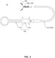
- FIG. 5 is an exemplary diagram illustrating a structure of an extension portion according to some embodiments of the present disclosure.
- the extension portion 400 may be provided with a bonding portion at a distal end 410, a curved portion 420, and a bonding portion at a proximal end 430.
- the bonding portion at the distal end 410 may be releasably connected to the clipping arm 320
- the curved portion 420 may connect the bonding portion at the distal end 410 to the bonding portion at the proximal end 430
- the bonding portion at the proximal end 430 may be connected to the core shaft 220.
- the plurality of clipping portions 310 may be sequentially arranged along an axial direction of the sheath pipe 210.
- the rest clipping portions 310 e.g., the second clipping portion 310B, etc. located between the first clipping portion 310A and the distal end of the sheath pipe 210 may remain connected to the bonding portion at the proximal end 430 of the extension portion 400.
- the extension portion 400 may move axially relative to the rest clipping portions 310.
- the curved portion 420 may be flexible. In some embodiments, the curved portion may be made of materials such as metallic stainless steel, etc. In some embodiments, by setting a bending degree of the curved portion 420 and/or an included angle between a connection region connecting the bonding portion at the distal end 410 and the curved portion 420, it is possible to set a distance between the first clipping arm 320A and the second clipping arm 320B when the clipping portions 310 are in the opening state.
- the extension portion 400 may be moved from a proximal end to a distal end to open the first clipping portion 310A located in the bonding portion at the distal end 410 of the extension portion 400, and the curved portion 420 causes a larger distance between the first clipping arm 320A and the second clipping arm 320B.
- the curved portion 420 may be bent outward along a radial direction (i.e., a concave surface of the curved portion 420 is turned away from an axis of the clip devices 300) relative to the bonding portion at the proximal end 430, and the curved portion 420 may be bent inward along the radial direction (i.e., the concave surface of the curved portion 420 is turned towards the axis of the clip devices 300) relative to the bonding portion at the distal end 410.
- a radial direction i.e., a concave surface of the curved portion 420 is turned away from an axis of the clip devices 300
- the curved portion 420 may be bent inward along the radial direction (i.e., the concave surface of the curved portion 420 is turned towards the axis of the clip devices 300) relative to the bonding portion at the distal end 410.
- the radial direction refers to a radial direction of the sheath pipe 210 or a radial direction of the clip devices 300, which is perpendicular to an axis of the sheath pipe 210 or the axis of the clip devices 300.
- the curved portion 420 may be curved, and the bonding portion at the proximal end 430 may be tangent to the curved portion 420, reducing resistance and wear at a junction of the bonding portion at the proximal end 430 and the curved portion 420 as the bonding portion at the proximal end 430 moves in and out of the clipping portion 310 or the sheath pipe 210.
- a junction between the bonding portion at the distal end 410 and the curved portion 420 may have a rounded and smooth transition to reduce the concentration of stress at the junction between the bonding portion at the distal end 410 and the curved portion 420, preventing the bonding portion at the distal end 410 from fracturing at the junction.
- the curved portion 420 may include, but is not limited to, an arcuate, a folded line, or other curved shape.
- FIG. 6 is an exemplary diagram illustrating a structure of a connecting member according to some embodiments of the present disclosure.
- FIG. 7 is a first exemplary diagram illustrating a structure of a clipping arm according to some embodiments of the present disclosure.
- the first connecting portion 710 may mate with the first mating portion 330
- the second connecting portion 720 may mate with the second mating portion 340 to achieve the connection between two of the clipping portions 310 and/or the connection between the clipping portions 310 and the sheath pipe 210.
- a release of the mating of the first connecting portion 710 and the first mating portion 330 and a release of the mating of the second connecting portion 720 and the second mating portion 340 may achieve a release of the connection between two of the clipping portions 310, and/or a release of the connection between the clipping portions 310 and the sheath pipe 210.
- a distal end of the connecting member 700 may be provided on the proximal end of the first clipping portion 310A and may mate with the first mating portion 330 through the first connecting portion 710, and the proximal end of the connecting member 700 may be provided on the distal end of the second clipping portion 310B and may mate with the second mating portion 340 through the second connecting portion 720, to realize the connection between the first clipping portion 310A and the second clipping portion 310B.
- a release of the mating of the first connecting portion 710 and the first mating portion 330 and a release of the mating of the second connecting portion 720 and the second mating portion 340 may achieve a release of connection between the first clipping portion 310A and the second clipping portion 310B.
- the connecting member 700 may be constructed in a tabular structure to reduce the radial space that the connecting member 700 takes up in the clipping portion 310.
- the connecting member 700 may also be constructed in other structures, such as an elongate structure, which is not limited in the present disclosure.
- the first connecting portion 710 may include a snap hook 711.
- the snap hook 711 may include two resilient support arms 7111 and hook structures 7112.
- a proximal end of each of the two resilient support arms 7111 may be connected to the proximal end of the connecting member 700, and a distal end of each of the two resilient support arms 7111 may extend to the distal end of the connecting member 700 and may be formed as a free end.
- the hook structure 7112 may be provided on the distal end of each of the two resilient support arms 7111, and two hook structures 7112 on the two resilient support arms 7111 may be provided opposite each other.
- the two resilient support arms 7111 of the snap hook 711 may deform and depart away from each other, and the hook structure 7112 may be disengaged from the limit column.
- the hook structure 7112 of the snap hook 711 may break away from the distal end of each of the resilient support arms 7111 to achieve a release of connection between the snap hook 711 and the limit column.
- the hook structure 7112 may rotate relative to each of the resilient support arms 7111 to achieve a release of connection between the snap hook 711 and the limit column.
- deformation, fracture, or displacement of the limit column of the first mating portion 330 may achieve a release of the mating of the first connecting portion 710 and the first mating portion 330.
- the connecting member 700 may include a tab 721 constructed as a resilient arch. One end of the tab 721 may be connected to the proximal end of the connecting member 700, another end may be formed toward the distal end of the connecting member 700 as a free end, and an outer arched surface of the tab 721 may be constructed as the second connecting portion 720.
- the tab 721 may be provided between the two resilient support arms 7111 of the first connecting portion 710, and the tab 721 may bend into an arch shape in a thickness direction of the connecting member 700.
- an axial length of the tab 721 may be less than an axial length of each of the resilient support arms 7111.
- the second mating portion 340 of the clipping portion 310 may include a limit surface.
- the outer arched surface of the tab 721 may mate with the limit surface to cause the second connecting portion 720 to mate with the second mating portion 340.
- a release of the mating of the outer arched surface of the tab and the limit surface achieves a release of the mating of the second connecting portion 720 and the second mating portion 340.
- the tab 721 may be deformed in the thickness direction of the connecting member 700 by being subjected to a force, and the deformation of the tab 721 causes the second connecting portion 720 (i.e., the outer arched surface of the tab 721) to protrude from a surface of the connecting member 700 along the thickness direction.
- the outer arched surface may mate with the limit surface, and the outer arched surface may return to its original shape and the mating of the outer arched surface and the limit surface may be released when the force on the tab 721 is released.
- first connecting portion 710 and the second connecting portion 720 may include other structures
- first mating portion 330 and the second mating portion 340 may include other structures, which may be referred to in the structure of the connecting member 700 in example two below but not constitute a limitation on the structure of the connecting member 700 in the present disclosure.
- the third connecting portion 730 and the second connecting portion 720 may be different portions in an integral structure, and the second connecting portion 720 may be deformed or displaced to form the third connecting portion 730.
- the connecting member 700 may include the tab 721, with one end of the tab 721 being connected to the proximal end of the connecting member 700, and another end of the tab 721 being formed towards the distal end of the connecting member 700 as a free end, which constitutes the third connecting portion 730. More descriptions regarding the tab 721 may be found in related descriptions of the tab 721 hereinabove.
- the extension portion 400 may be moved from the distal end to the proximal end, and when the extension portion 400 provides a sufficiently large operating force on the third connecting portion 730, the tab 721 and the snap hook 711 may be deformed simultaneously, the deformation of the tab 721 may change the shape or state of the second connecting portion 720 to achieve the release of the mating of the second connecting portion 720 and the second mating portion 340, and the deformation of the snap hook 711 may achieve the release of the mating of the first connecting portion 710 and the first mating portion 330.
- the second clipping portion 310B is connected to the distal end of the extension portion 400 and may be configured to clip the tissue, and after the distal end of the extension portion 400 enters into the second clipping portion 310B, the third mating portion 440 of the extension portion 400 may mate with the third connecting portion 730 of the first connecting member 700A.
- the extension portion 400 may drive the first connecting member 700A to move into the third clipping portion 310C, at this time a release of the connection between the second clipping portion 310B and the third clipping portion 310C may be achieved.
- the third clipping portion 310C is connected to the distal end of the extension portion 400, at this time, the third clipping portion 310C may be configured to clip the tissue.
- the extension portion 400 continues to move from the distal end to the proximal end until the proximal end of the first connecting member 700A abuts against the distal end of the second connecting member 700B.
- the resisting portion 312 may also be a structure different from the first mating portion 330, which is capable of preventing the connecting member 700 from moving from the distal end to the proximal end.
- FIG. 8 is an exemplary diagram illustrating a structure of a bonding member according to some other embodiments of the present disclosure.
- FIG. 9 is a second exemplary diagram illustrating a structure of a clipping arm according to some embodiments of the present disclosure.
- the clip device 300 may further include the bonding member 600, the bonding member 600 may be configured to releasably connect at least one of the clipping portions 310 to the extension portion 400.
- the bonding member 600 may be configured to releasably connect at least one of the clipping portions 310 to the extension portion 400.
- a release of the connection between the bonding member 600 and the clipping portions 310, and/or a release of the connection between the extension portion 400 and the bonding member 600 may achieve a release of the connection between the clipping portions 310 and the extension portion 400.
- the first docking portion 450 of the extension portion 400 may include a first groove provided on the bonding portion at the distal end 410 of the extension portion 400, and the first groove may include, but is not limited to, a countersunk groove, an aperture groove, etc.
- the first bonding portion 610 of the connecting member 700 may include a bending structure.
- the first groove and the bending structure are releasably limitedly connected.
- the first groove and the bending structure are limitedly connected to limit an axial relative displacement of the extension portion 400 and the bonding member 600, at this time, the extension portion 400 is connected to the bonding member 600.
- the bending structure may be released from the first groove by deformation, fracture, and displacement when subjected to a force from a distal end to a proximal end, at this time, the extension portion 400 is released from the bonding member 600.
- the bending structure is bent in a smooth transition bending in a circular arc shape, avoiding a phenomenon of stress concentration, and preventing the phenomenon of fracture of the bending structure caused by external force.
- the deformation portion 621 may include a first bevel 622 radially outward inclined from a distal end to a proximal end
- the second docking portion 350 of the clipping portion 310 may include a second bevel 351 parallel or substantially parallel to the first bevel 622.
- Being substantially parallel refers to that an included angle between the first bevel 622 and the second bevel 351 is within a range of 0-5°.
- the first snap portion 360 may include a second groove
- the second snap portion 470 may include a resilient projection.
- a proximal sidewall of the second groove may be inclined from inward to outward toward the distal end of the clipping portions 310
- the resilient projection may be an oblique projection that is inclined at the same or substantially the same angle as the proximal sidewall of the second groove.
- the resilient projection When the extension portion 400 is moved from the proximal end to the distal end, the resilient projection abuts against the sidewall of the second groove and is not easily dislodged from the second groove, so that the clipping portions 310 remain on the extension portion 400.
- the clipping portion 310 may include a first clipping arm 320A, a second clipping arm 320B, and a locking portion 500.
- the locking portion 500 may include a first locking portion 500A provided on the first clipping arm 320A and a second locking portion 500B provided on the second clipping arm 320B.
- the first locking portion 500A may include a locking convexity 510 and the second locking portion 500B may include a locking concavity 520.
- the first clipping arm 320A may include a locking convexity 510 and a locking concavity 520 on both sides, respectively, of the first clipping arm 320A
- the second clipping arm 320B may include a locking concavity 520 and a locking convexity 510 on both sides, respectively, of the second clipping arm 320B.
- the locking convexity 510 is constructed as a limiting clasp, and the locking concavity 520 is constructed as a catch.
- one end of the limiting clasp is fixed to the clipping arm 320, and the other end of the limiting clasp is formed as a snap end with an increased cross-section.
- the catch may be a limiting slot formed by a combination of two support arms. The snap end of the limiting clasp extends into the catch to form a snap fit, and the locking convexity 510 locks with the locking concavity 520.
- the locking portion 500 may be integrally molded with the clipping portions 310. In some embodiments, the locking portion 500 may be molded separately from the clipping portions 310. In some embodiments, the locking convexity 510 and the locking concavity 520 may be constructed in other structures.
- the deformation portion 621 of the bonding member 600 has a locking effect on two clipping arms 320 of the clipping portions 310.
- the clipping portions 310 may include a first locking slot 511 provided on the locking convexity 510, a second locking slot 512 provided on the locking convexity 510, and a third locking slot 521 provided on the locking concavity 520.
- the second locking slot 512 of the first clipping arm 320A may be connected to the third locking slot 521 of the second clipping arm 320B.
- the extension portion 400 may be moved from a distal end to a proximal end, causing the deformation portion 621 of the bonding member 600 to deform or be displaced, one of the stand bars of the deformation portion 621 may extend into the first locking slot 511, and the other of the stand bars may simultaneously extend into the second locking slot 512 and the third locking slot 521. At this time, the first clipping arm 320A and the second clipping arm 320B may be locked. In some embodiments, when the clipping portion 310 is released from the extension portion 400, the deformation portion 621 of the bonding member 600 is maintained in a post-deformation state, so that the clipping portion 310, which stays in the body, remains locked.
- one stand bar of the second bonding portion 620 of the first bonding member 600A may mate with the first locking slot 511 of the first clipping portion 310A, and the other stand bar may mate with the third locking slot 521 of the first clipping portion 310A, at this time, the two stand bars of the second bonding portion 620 are not deformed.
- the first snap portion 360 of the first clipping portion 310A (as illustrated in FIG. 9 ) may mate with the second snap portion 470 of the extension portion 400.
- the first connecting portion 710 of the first connecting member 700A may mate with the first mating portion 330 of the second clipping portion 310B, and the tab 721 of the first connecting member 700A may be extruded and deformed, causing the second connecting portion 720 to mate with the second mating portion 340 of the third clipping portion 310C.
- the first connecting portion 710 of the second connecting member 700B may mate with the first mating portion 330 of the third clipping portion 310C, and the second connecting portion 720 of the second connecting member 700B may be extruded and deformed and may mate with the second mating portion 340 of the sheath pipe 210.
- FIG. 13 is an exemplary diagram illustrating a structure of a connecting member according to some embodiments of the present disclosure.
- FIG. 14 is an exemplary diagram illustrating a structure of an extension position according to some embodiments of the present disclosure.
- the tab 721 is constructed as a resilient arch.
- the connecting member 700 is provided in the clipping portion 310 or the sheath pipe 210, in the thickness direction of the connecting member 700, the tab 721 is deformed by squeezing so that the second connecting portion 720 may mate with the second mating portion 340 of the clipping portion 310.
- the first clipping portion 310A is in a closed state
- the second clipping portion 310B and the third clipping portion 310C are in a closed state.
- the extension portion 400 is moved from the distal end to the proximal end so that the first connecting portion 710 of the first connecting member 700A crosses over the first mating portion 330 of the second clipping portion 310B, the second connecting portion of the first connecting member 700A separates from the second mating portion 340 of the third clipping portion 310C, thereby driving the first connecting member 700A to move into the third clipping portion 310C, so that a release of the connection between the second clipping portion 310B and the third clipping portion 310C is achieved.
- the extension portion 400 continues to move from the distal end to the proximal end to control the second connecting member 700B to release the third clipping portion 310C from the sheath pipe 210 in a similar manner to the above-described releasing process, which may not be repeated in the present disclosure.
- FIG. 16 is a diagram illustrating a cross section of an assembly of a clip device according to some embodiments of the present disclosure.
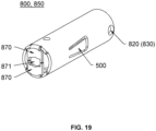
- the storage pipe 800 may include a passage 810 that accommodates the clipping portion 310.
- the first storage pipe 800A may include a first passage 810A, and a proximal end of the first clipping portion 310A may be stored within the first passage 810A.
- the second storage pipe 800B may include a second passage 810B, and a proximal end of the second clipping portion 310B may be stored within the second passage 810B. Storing the clipping portion 310 through the passage 810 of the storage pipe 800 keeps the clipping portion 310 in a closed state to achieve locking of the clipping portion 310.
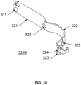
- each of the clipping portions 310 may include the first clipping arm 320A and the second clipping arm 320B.
- the first clipping arm 320A and the second clipping arm 320B include a clipping claw 321 provided on a distal end and a curved arm 322 provided on a proximal end, respectively, and the clipping claw 321 is configured to clip the tissue.
- the curved arm 322 is flexible. At least a portion of the curved arm 322 is curved when located outside of the storage pipe 800, which may provide a greater span for the clipping claw 321.
- the distal end of the at least one clipping portion 310 is provided with a first outer connecting portion 311, and the proximal end of the at least one storage pipe 800 is provided with a first outer connecting hole 820, the first outer connecting portion 311 may mate with the first outer connecting hole 820, making the clipping portions 310 connected to the storage pipe 800.
- the first outer connecting portion 311 may mate with the first outer connecting hole 820, the first clip device 300A may be connected to the second clip device 300B. A release of the mating of the first outer connecting portion 311 and the first outer connecting hole 820 achieves a release of the connection between the first clip device 300A and the second clip device 300B.
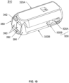
- FIG. 20 is an exemplary diagram illustrating a structure of a bushing according to some embodiments of the present disclosure.
- the conveying device 200 further may include a bushing 230, the proximal end of the bushing 230 is removably connected to the distal end of the sheath pipe 210, the bushing 230 is provided with a second outer connecting portion 231, the second storage pipe 800B is provided with a second outer connecting hole 830, the second outer connecting portion 231 releasably cooperates with the second outer connecting hole 830.
- the second clip device 300B is connected to the sheath pipe 210 when the second outer connecting portion 231 may mate with the second outer connecting hole 830. A release of the connection between the second clip device 300B and the sheath pipe 210 is achieved when a release of the mating of the second outer connecting portion 231 and the second outer connecting hole 830 is achieved.
- two elastic arms 232 are provided on the distal end of the bushing 230, with a bonding hole 233 formed between the two elastic arms 232 to allow the core shaft 220 to pass through, and the elastic arms 232 are provided with second outer connecting portion 231 formed by convex portions.
- the spacer portion 900 is releasably provided on the distal end of the second clipping portion 310B, which may spread the first outer connecting portion 311 in a radial direction.
- a distal end of the second clipping portion 310B may be stored in the first passage 810A, and when the spacer portion 900 is combined with the distal end of the second clipping portion 310B, the first outer connecting portion 311 provided on the second clipping portion 310B is radially moved outward to be combined with the first outer connecting hole 820 of the first storage pipe 800A, and the second clipping portion 310B is connected to the first storage pipe 800A.
- the spacer portion 900 is releasably provided on a distal end of the sheath pipe 210, which may spread the second outer connecting portion 231 in the radial direction.
- the spacer portion 900 combines with two elastic arms 232 of the bushing 230, the elastic arms 232 undergoes resilient outward expansion, the second outer connecting portion 231 provided in the bushing 230 is moved radially outward to combine with the second outer connecting hole 830 of the second storage pipe 800B, and the sheath pipe 210 is connected to the second storage pipe 800B.
- the spacer portion 900 is not connected to the bushing 230 of the sheath pipe 210, the second outer connecting portion 231 provided on the bushing 230 is moved radially inward, the second outer connecting portion 231 is not connected to the second outer connecting hole 830 of the second storage pipe 800B, and a release of the connection the sheath pipe 210 and the second storage pipe 800B is achieved.
- the core shaft 220 is withdrawn from the bonding hole 233 by moving from a distal end to a proximal end, and after the connecting head 221 abuts against the spacer portion 900, the connecting head 221 continues to move from the distal end to the proximal end such that the connecting head 221 drives the spacer portion 900 to move from a distal end to a proximal end.
- the spacer portion 900 is withdrawn from an accommodating space between the elastic arms 232 of the bushing 230, the elastic arms 232 are resiliently contracted, a size of the bonding hole 233 decreases so that the second outer connecting portion 231 is moved radially inward, the second outer connecting portion 231 is not connected to the second outer connecting hole 830 of the second storage pipe 800B, and a release of the connection between the second storage pipe 800B and the bushing 230 of the sheath pipe 210 is achieved.
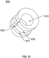
- the spacer portion 900 may include a mating slot 930, the mating slot 930 is formed on an outer surface of the spacer portion 900 and extends as an annular slot in a circumferential direction of the spacer portion 900.
- the mating slot 930 is configured to accommodate the distal end of the clipping portion 310, and/or the distal ends of the two elastic arms 232 of the bushing 230 of the sheath pipe 210, such that the clipping portion 310 and/or the elastic arms 232 are releasably axially limited with the spacer portion 900.
- the spacer portion 900 may be integrally molded with the connecting head 221.
- a diameter of the core shaft 220 is set such that the first outer connecting portion 311 is connected to the first outer connecting hole 820 and the second outer connecting portion 231 is connected to the second outer connecting hole 830.
- the spacer portion 900 may be a mating slot recessed inward on the connecting head 221, and a structure of the mating slot may be found in the structure of the mating slot 930 of the spacer portion 900 described above.
- a proximal end of the first clipping arm 320A is provided with an inner connecting hole 324
- a proximal end of the second clipping arm 320B is also provided with the inner connecting hole 324.
- a distal end of the core shaft 220 is provided with a connecting head 221, and the connecting head 221 is provided with a large diameter portion and a small diameter portion from a distal end to a proximal end.
- the proximal end of the first clipping arm 320A is provided with a bending portion 323
- the proximal end of the second clipping arm 320B is also provided with the bending portion 323
- the inner connecting hole 324 is provided on the bending portion 323.
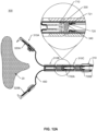
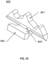
- FIG. 23 is an exemplary diagram illustrating a structure of a limit portion according to some embodiments of the present disclosure.
- At least one of the clipping portions 310 may include a fixing hole 328 (or referred to as a second hole), the fixing hole 328 is provided on the first clipping arm 320A and the second clipping arm 320B, respectively.
- the fixing hole 328 is provided in a junction between the clipping claws 321 and the curved arm 322.
- the storage pipe 800 may include a limit portion 840, and the limit portion 840 is releasably connected to the fixing hole 328.
- the clipping portion 310 is fixed relative to the storage pipe 800 when the limit portion 840 is connected to the fixing hole 328.
- the clipping portion 310 may move relative to the storage pipe 800 when the limit portion 840 is not connected to the fixing hole 328.
- a limit portion 840 is radially movable at the distal end of the storage pipe 800, and the limit portion 840 may include a fixing end 842 and a fixing claw 841.
- the fixing claw 841 moves radially outward and bonds within the fixing hole 328 when the fixing end 842 contacts with the core shaft 220.
- the fixing claw 841 moves radially inward and withdraws the fixing hole 328 when the fixing end 842 does not in contact with the core shaft 220.
- the fixing claw 841 may snap the fixing hole 328, and the fixing end 842 is provided in the storage pipe 800.
- the limit portion 840 further may include a sliding slot 843 provided between the fixing end 842 and the fixing claw 841, a distal end of the storage pipe 800 is provided with a blocking portion 870, and the limit portion 840 is connected to the second storage pipe 800B.
- the distal end of the second storage pipe 800B is provided with a blocking portion 870, the sliding slot 843 is snapped to the blocking portion 870, and the fixing end 842 is stored in the second passage 810B.
- the blocking portion 870 is also provided with a penetrating hole 871, and the core shaft 220 may move radially axially in the penetrating hole 871.
- the fixing claw 841 is bonded within the fixing hole 328, and the second clipping portion 310B is fixed relative to the second storage pipe 800B.
- the fixing claw 841 is not bonded within the fixing hole 328, and the second clipping portion 310B may be moved relative to the second storage pipe 800B.
- FIG. 24 is an exemplary diagram illustrating a structure of an inner pipe according to some embodiments of the present disclosure.
- the first storage pipe 800A and the second storage pipe 800B are both of split-molded structure, and the split-molding processing process is simple, and the cost is lower.
- the first storage pipe 800A and the second storage pipe 800B include an external pipe 850 and an internal pipe 860, respectively, and the internal pipe 860 is socketed within the passage 810 of the external pipe 850, and the passage 810 of the first storage pipe 800A and second storage pipe 800B is shared by the external pipe 850 and internal pipe 860.
- the wall of the internal pipe 860 forms a locking stopper 540, the locking stopper 540 may limit the pin roll 326 to continually move from the distal end to the proximal end.
- the first storage pipe 800A and the second storage pipe 800B are integrally molded, and the locking stopper 540 is provided directly within the wall of the first storage pipe 800A and the wall of the second storage pipe 800B.
- the integral molding reduces accessories and makes assembly easier. Whether the storage pipe 800 is molded separately or molded integrally, the locking stopper 540 is provided in conjunction with the ends of the pin roll 326, thereby limiting the movement of the clip device 300 from a distal end to a proximal end.
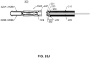
- FIG.25A-FIG.25J are schematic diagrams illustrating a clipping and releasing process of a clipping portion according to some embodiments of the present disclosure.
- the two clip devices 300 respectively include the first clipping portion 310A and the second clipping portion 310B.
- a count of clip devices 300 in the embodiment is for illustrative purposes only and does not limit a count of clipping portions 310 in the embodiments of the present disclosure.
- For the clip apparatus 10 with a different count of clip devices 300 please refer to the clipping process shown in FIG. 25A-FIG. 25J .
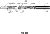
- the clip device 300 is in a first state where the clip device 300 enters into a passage of the endoscopic, and the first clip device 300A provided on a most distal end moves close to the tissue (not shown in the figure).
- the first clip device 300A and the second clip device 300B are provided from a distal end to a proximal end outside the second storage pipe 800B of the sheath pipe 210 of the conveying device 200.
- a proximal end of the second clipping portion 310B is stored in the second passage 810B, a distal end of the clipping arm 320 of the second clipping portion 310B is provided with a convex portion (the first outer connecting portion 311), and a spacer portion 900 running through the outside of the core shaft 220 is combined with the second clipping portion 310B so that the convex portion (the first outer connecting portion 311) moves radially outward and extends into the first outer connecting hole 820 of the first storage pipe 800A, thereby realizing the connection between the first clip device 300A and the second clip device 300B.
- the fixing claw 841 of the limit portion 840 which mutually abuts against the core shaft 220, extends into the fixing hole 328 provided in the second clipping portion 310B, to make the second clip device 300B move with the axial movement of the core shaft 220.
- Another spacer portion 900 running through the outside of the core shaft 220 is combined with the bushing 230 so that the convex portion (the second outer connecting portion 231) moves radially outward and extends into the second outer connecting hole 830 provided in the second storage pipe 800B, so as to realize the connection between the second clip device 300B and the sheath pipe 210.
- the clip device 300 is in the seventh state.
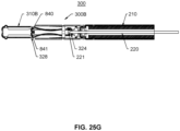
- the core shaft 220 continues to move from the distal end to the proximal end, and when the core shaft 220 is not connected to the limit portion 840, the fixing claw 841 of the limit portion 840 is moved radially inward and disengaged from the fixing hole 328 of the second clipping portion 310B, the second clipping portion 310B may move relative to the second storage pipe 800B.
- the clip device 300 is in an eighth state. After completion of the inner connection between the core shaft 220 and the second clip device 300B, the core shaft 220 is moved from the proximal end to the distal end, and the second clipping portion 310B is not constrained by the action of the limit portion 840, and the first clipping arm 320A and second clipping arm 320B of the second clipping portion 310B depart away from each other for receiving the tissue.
- the clip device 300 is in the ninth state.
- the core shaft 220 is moved from the distal end to the proximal end, and the second clipping portion 310B provided on the most distal end is in the closed state, i.e., the first clipping arm 320A and the second clipping arm 320B are close to each other after receiving the tissue.
- the core shaft 220 moves axially freely from the penetrating hole 871 of the blocking portion 870 provided on the second storage pipe 800B, and the second clip device 300B and the sheath pipe 210 remain connected.
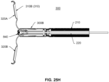
- the clip device 300 is in a tenth state.
- the core shaft 220 continues to move from the distal end to the proximal end, and the force from the distal end to the proximal end subjected to the connecting head 221 of the distal end of the core shaft 220 acts on the proximal end of the first clipping arm 320A and the proximal end of said second clipping arm 320B such that the proximal end of the first clipping arm 320A and the proximal end of the second clipping arm 320B are deformed or displaced, the connecting head 221 is withdrawn from the inner connecting hole 324, and the core shaft 220 separates from the second clipping portion 310B.
Landscapes
- Health & Medical Sciences (AREA)
- Surgery (AREA)
- Life Sciences & Earth Sciences (AREA)
- Heart & Thoracic Surgery (AREA)
- Nuclear Medicine, Radiotherapy & Molecular Imaging (AREA)
- Engineering & Computer Science (AREA)
- Biomedical Technology (AREA)
- Medical Informatics (AREA)
- Molecular Biology (AREA)
- Animal Behavior & Ethology (AREA)
- General Health & Medical Sciences (AREA)
- Public Health (AREA)
- Veterinary Medicine (AREA)
- Vascular Medicine (AREA)
- Reproductive Health (AREA)
- Surgical Instruments (AREA)
Applications Claiming Priority (5)
| Application Number | Priority Date | Filing Date | Title |
|---|---|---|---|
| CN202111111648 | 2021-09-18 | ||
| CN202111162631 | 2021-09-30 | ||
| CN202111334658 | 2021-11-11 | ||
| CN202210896808 | 2022-07-28 | ||
| PCT/CN2022/119233 WO2023041011A1 (zh) | 2021-09-18 | 2022-09-16 | 夹子器械 |
Publications (2)
| Publication Number | Publication Date |
|---|---|
| EP4397253A1 true EP4397253A1 (de) | 2024-07-10 |
| EP4397253A4 EP4397253A4 (de) | 2025-03-19 |
Family
ID=85602456
Family Applications (1)
| Application Number | Title | Priority Date | Filing Date |
|---|---|---|---|
| EP22869378.4A Pending EP4397253A4 (de) | 2021-09-18 | 2022-09-16 | Klammerinstrument |
Country Status (4)
| Country | Link |
|---|---|
| US (1) | US20240398423A1 (de) |
| EP (1) | EP4397253A4 (de) |
| CN (1) | CN117940077A (de) |
| WO (1) | WO2023041011A1 (de) |
Families Citing this family (3)
| Publication number | Priority date | Publication date | Assignee | Title |
|---|---|---|---|---|
| WO2025162363A1 (zh) * | 2024-01-31 | 2025-08-07 | 杭州安杰思医学科技股份有限公司 | 一种夹子器械及其操作方法 |
| CN120392209A (zh) * | 2024-01-31 | 2025-08-01 | 杭州安杰思医学科技股份有限公司 | 一种夹子器械及其控制方法 |
| CN121221206A (zh) * | 2024-06-28 | 2025-12-30 | 杭州安杰思医学科技股份有限公司 | 一种夹子器械及其控制方法 |
Family Cites Families (27)
| Publication number | Priority date | Publication date | Assignee | Title |
|---|---|---|---|---|
| US2256382A (en) * | 1939-03-06 | 1941-09-16 | Edward H Kruse | Surgical ligature applicator |
| US4296751A (en) * | 1979-08-02 | 1981-10-27 | Blake Joseph W Iii | Surgical device |
| US4556058A (en) * | 1983-08-17 | 1985-12-03 | United States Surgical Corporation | Apparatus for ligation and division with fixed jaws |
| DE3335985C2 (de) * | 1983-10-04 | 1986-12-04 | Aesculap-Werke Ag Vormals Jetter & Scheerer, 7200 Tuttlingen | Magazin zur Aufnahme von C-förmigen Scalpclips |
| US4671278A (en) * | 1985-01-14 | 1987-06-09 | Thomas J. Fogarty | Scalp hemostatic clip and dispenser therefor |
| US5192288A (en) * | 1992-05-26 | 1993-03-09 | Origin Medsystems, Inc. | Surgical clip applier |
| CH687060A5 (de) * | 1994-02-11 | 1996-09-13 | Alice Walder Utz Dr | Einstueckige Wundklammer. |
| SE0002878D0 (sv) * | 2000-08-11 | 2000-08-11 | Kimblad Ola | Device and method for treatment of atrioventricular regurgitation |
| JP4097924B2 (ja) * | 2001-02-05 | 2008-06-11 | オリンパス株式会社 | 生体組織のクリップ装置 |
| JP4059656B2 (ja) * | 2001-03-07 | 2008-03-12 | オリンパス株式会社 | 生体組織のクリップ装置 |
| DE10259411A1 (de) * | 2002-12-19 | 2004-07-08 | Forschungszentrum Karlsruhe Gmbh | Medizinischer Clip und Vorrichtung zum Applizieren eines solchen |
| US20050216036A1 (en) * | 2004-03-29 | 2005-09-29 | Nakao Naomi L | Endoscopic fastening system with multiple fasteners |
| JP4261450B2 (ja) * | 2004-09-22 | 2009-04-30 | Hoya株式会社 | 内視鏡用クリップ装置 |
| US20090318937A1 (en) * | 2008-06-24 | 2009-12-24 | Fujifilm Corporation | Clip coupling method and multiple clip package |
| JP5383222B2 (ja) * | 2009-01-26 | 2014-01-08 | 富士フイルム株式会社 | 連発式クリップ処置具 |
| US20140316440A1 (en) * | 2013-02-01 | 2014-10-23 | Mark Gordon | Multiple clip endoscopic tissue clipping system and device |
| DE112014003129A5 (de) * | 2013-07-04 | 2016-04-21 | medwork GmbH | Medizinischer Clip |
| SG11201705137PA (en) * | 2014-12-24 | 2017-07-28 | Edwards Lifesciences Corp | Suture clip deployment devices |
| RU2723729C1 (ru) * | 2016-08-08 | 2020-06-17 | Тачстоун Интернешнл Медикал Сайенс Ко., Лтд. | Хирургическое устройство для закрытия ткани |
| US10820903B2 (en) * | 2016-09-22 | 2020-11-03 | Boston Scientific Scimed, Inc. | Hemostasis clip with reloadable clipping mechanism |
| CN118021380A (zh) * | 2018-01-29 | 2024-05-14 | 波士顿科学国际有限公司 | 止血夹 |
| WO2020263629A1 (en) * | 2019-06-27 | 2020-12-30 | Auris Health, Inc. | Systems and methods for a medical clip applier |
| CN211355689U (zh) * | 2019-07-03 | 2020-08-28 | 安瑞医疗器械(杭州)有限公司 | 配合内窥镜使用的夹子装置及其夹持部 |
| CN211270957U (zh) * | 2019-10-29 | 2020-08-18 | 南微医学科技股份有限公司 | 一种医用止血夹 |
| WO2021226400A1 (en) * | 2020-05-08 | 2021-11-11 | Cedars-Sinai Medical Center | Systems and methods for hemoclip deployment |
| CN213406175U (zh) * | 2020-06-16 | 2021-06-11 | 苏州市倍咏医疗科技有限公司 | 一种多发式夹持装置 |
| CN212490043U (zh) * | 2020-06-16 | 2021-02-09 | 苏州市倍咏医疗科技有限公司 | 一种可连续释放的夹持装置 |
-
2022
- 2022-09-16 CN CN202280059916.7A patent/CN117940077A/zh active Pending
- 2022-09-16 WO PCT/CN2022/119233 patent/WO2023041011A1/zh not_active Ceased
- 2022-09-16 EP EP22869378.4A patent/EP4397253A4/de active Pending
- 2022-09-16 US US18/693,145 patent/US20240398423A1/en active Pending
Also Published As
| Publication number | Publication date |
|---|---|
| WO2023041011A1 (zh) | 2023-03-23 |
| CN117940077A (zh) | 2024-04-26 |
| US20240398423A1 (en) | 2024-12-05 |
| EP4397253A4 (de) | 2025-03-19 |
Similar Documents
| Publication | Publication Date | Title |
|---|---|---|
| EP4397253A1 (de) | Klammerinstrument | |
| EP3357436B1 (de) | Endoskopischer chirurgischer klammerapplikator | |
| JP7357170B2 (ja) | 3アームクランプ | |
| US12458363B2 (en) | Clip devices, clip apparatuses, and methods for unlocking of clip devices | |
| US11129623B2 (en) | Dual support jaw design | |
| EP3395260A1 (de) | Endoskopisches nahtligationswerkzeug | |
| US20240225629A1 (en) | Clip instruments | |
| CN214414866U (zh) | 内窥镜用多发处理装置 | |
| JP4935040B2 (ja) | 内視鏡用クリップ | |
| US20090223028A1 (en) | Magazine type clipping device | |
| CN211511934U (zh) | 止血夹 | |
| EP4582034A1 (de) | Einführvorrichtung zum schneiden von gewebe | |
| JP4475229B2 (ja) | 内視鏡用クリップ | |
| CN117062574A (zh) | 一体式夹持件的制造方法 | |
| CN115884718B (zh) | 插入式组织夹闭装置及其运动杆 | |
| EP4582035A1 (de) | Einführvorrichtung zum schneiden von gewebe und kipphebel dafür | |
| EP4582032A1 (de) | Einführvorrichtung zum schneiden von gewebe und bewegungssteuerungsanordnung dafür | |
| WO2023173694A1 (zh) | 插入式组织夹闭装置及其夹持件 | |
| JP7795159B2 (ja) | クリップ装置 | |
| CN115399831B (zh) | 插入式组织夹闭装置 | |
| CN120916710A (zh) | 缝合收紧构件 | |
| CN118524812A (zh) | 止血夹和组织夹闭装置 | |
| JP2010004941A (ja) | 筒状部材、及び連発式クリップ処置具 | |
| JP2010119682A (ja) | 筒状部材、及び連発式クリップ処置具 |
Legal Events
| Date | Code | Title | Description |
|---|---|---|---|
| STAA | Information on the status of an ep patent application or granted ep patent |
Free format text: STATUS: THE INTERNATIONAL PUBLICATION HAS BEEN MADE |
|
| PUAI | Public reference made under article 153(3) epc to a published international application that has entered the european phase |
Free format text: ORIGINAL CODE: 0009012 |
|
| STAA | Information on the status of an ep patent application or granted ep patent |
Free format text: STATUS: REQUEST FOR EXAMINATION WAS MADE |
|
| 17P | Request for examination filed |
Effective date: 20240331 |
|
| AK | Designated contracting states |
Kind code of ref document: A1 Designated state(s): AL AT BE BG CH CY CZ DE DK EE ES FI FR GB GR HR HU IE IS IT LI LT LU LV MC MK MT NL NO PL PT RO RS SE SI SK SM TR |
|
| REG | Reference to a national code |
Ref country code: DE Ref legal event code: R079 Free format text: PREVIOUS MAIN CLASS: A61B0017128000 Ipc: A61B0017080000 |
|
| DAV | Request for validation of the european patent (deleted) | ||
| DAX | Request for extension of the european patent (deleted) | ||
| RIC1 | Information provided on ipc code assigned before grant |
Ipc: A61B 90/00 20160101ALN20241120BHEP Ipc: A61B 17/10 20060101ALI20241120BHEP Ipc: A61B 17/08 20060101AFI20241120BHEP |
|
| A4 | Supplementary search report drawn up and despatched |
Effective date: 20250217 |
|
| RIC1 | Information provided on ipc code assigned before grant |
Ipc: A61B 90/00 20160101ALN20250211BHEP Ipc: A61B 17/10 20060101ALI20250211BHEP Ipc: A61B 17/08 20060101AFI20250211BHEP |