EP4397226A2 - Reinigungsvorrichtung mit mehreren ausrichtungen - Google Patents
Reinigungsvorrichtung mit mehreren ausrichtungen Download PDFInfo
- Publication number
- EP4397226A2 EP4397226A2 EP24169306.8A EP24169306A EP4397226A2 EP 4397226 A2 EP4397226 A2 EP 4397226A2 EP 24169306 A EP24169306 A EP 24169306A EP 4397226 A2 EP4397226 A2 EP 4397226A2
- Authority
- EP
- European Patent Office
- Prior art keywords
- cleaning
- cleaning device
- pump
- storage container
- container
- Prior art date
- Legal status (The legal status is an assumption and is not a legal conclusion. Google has not performed a legal analysis and makes no representation as to the accuracy of the status listed.)
- Pending
Links
Images









Classifications
-
- B—PERFORMING OPERATIONS; TRANSPORTING
- B05—SPRAYING OR ATOMISING IN GENERAL; APPLYING FLUENT MATERIALS TO SURFACES, IN GENERAL
- B05B—SPRAYING APPARATUS; ATOMISING APPARATUS; NOZZLES
- B05B15/00—Details of spraying plant or spraying apparatus not otherwise provided for; Accessories
- B05B15/30—Dip tubes
-
- A—HUMAN NECESSITIES
- A47—FURNITURE; DOMESTIC ARTICLES OR APPLIANCES; COFFEE MILLS; SPICE MILLS; SUCTION CLEANERS IN GENERAL
- A47L—DOMESTIC WASHING OR CLEANING; SUCTION CLEANERS IN GENERAL
- A47L13/00—Implements for cleaning floors, carpets, furniture, walls, or wall coverings
- A47L13/10—Scrubbing; Scouring; Cleaning; Polishing
- A47L13/20—Mops
- A47L13/22—Mops with liquid-feeding devices
-
- A—HUMAN NECESSITIES
- A47—FURNITURE; DOMESTIC ARTICLES OR APPLIANCES; COFFEE MILLS; SPICE MILLS; SUCTION CLEANERS IN GENERAL
- A47L—DOMESTIC WASHING OR CLEANING; SUCTION CLEANERS IN GENERAL
- A47L13/00—Implements for cleaning floors, carpets, furniture, walls, or wall coverings
- A47L13/10—Scrubbing; Scouring; Cleaning; Polishing
- A47L13/20—Mops
- A47L13/24—Frames for mops; Mop heads
- A47L13/254—Plate frames
-
- A—HUMAN NECESSITIES
- A47—FURNITURE; DOMESTIC ARTICLES OR APPLIANCES; COFFEE MILLS; SPICE MILLS; SUCTION CLEANERS IN GENERAL
- A47L—DOMESTIC WASHING OR CLEANING; SUCTION CLEANERS IN GENERAL
- A47L13/00—Implements for cleaning floors, carpets, furniture, walls, or wall coverings
- A47L13/10—Scrubbing; Scouring; Cleaning; Polishing
- A47L13/42—Details
- A47L13/46—Securing scouring or polishing cloths or sponges to the handles by gripping means, tongs, or the like
-
- B—PERFORMING OPERATIONS; TRANSPORTING
- B05—SPRAYING OR ATOMISING IN GENERAL; APPLYING FLUENT MATERIALS TO SURFACES, IN GENERAL
- B05B—SPRAYING APPARATUS; ATOMISING APPARATUS; NOZZLES
- B05B1/00—Nozzles, spray heads or other outlets, with or without auxiliary devices such as valves, heating means
- B05B1/30—Nozzles, spray heads or other outlets, with or without auxiliary devices such as valves, heating means designed to control volume of flow, e.g. with adjustable passages
- B05B1/3006—Nozzles, spray heads or other outlets, with or without auxiliary devices such as valves, heating means designed to control volume of flow, e.g. with adjustable passages the controlling element being actuated by the pressure of the fluid to be sprayed
-
- B—PERFORMING OPERATIONS; TRANSPORTING
- B05—SPRAYING OR ATOMISING IN GENERAL; APPLYING FLUENT MATERIALS TO SURFACES, IN GENERAL
- B05B—SPRAYING APPARATUS; ATOMISING APPARATUS; NOZZLES
- B05B15/00—Details of spraying plant or spraying apparatus not otherwise provided for; Accessories
- B05B15/40—Filters located upstream of the spraying outlets
-
- B—PERFORMING OPERATIONS; TRANSPORTING
- B05—SPRAYING OR ATOMISING IN GENERAL; APPLYING FLUENT MATERIALS TO SURFACES, IN GENERAL
- B05B—SPRAYING APPARATUS; ATOMISING APPARATUS; NOZZLES
- B05B9/00—Spraying apparatus for discharge of liquids or other fluent material, without essentially mixing with gas or vapour
- B05B9/03—Spraying apparatus for discharge of liquids or other fluent material, without essentially mixing with gas or vapour characterised by means for supplying liquid or other fluent material
- B05B9/04—Spraying apparatus for discharge of liquids or other fluent material, without essentially mixing with gas or vapour characterised by means for supplying liquid or other fluent material with pressurised or compressible container; with pump
- B05B9/08—Apparatus to be carried on or by a person, e.g. of knapsack type
- B05B9/085—Apparatus to be carried on or by a person, e.g. of knapsack type with a liquid pump
- B05B9/0855—Apparatus to be carried on or by a person, e.g. of knapsack type with a liquid pump the pump being motor-driven
- B05B9/0861—Apparatus to be carried on or by a person, e.g. of knapsack type with a liquid pump the pump being motor-driven the motor being electric
Definitions
- the present application is a continuation-in-part application of United States Patent Application Serial No. 16/032,846 filed on July 11, 2018 , which is a divisional application of United States Patent Application Serial No. 15/704,993 filed on September 14, 2017 , now United States Patent 10,070,766 , which claims the benefit of United States Provisional Application Serial No. 62/394,643 filed on September 14, 2016 and claims the benefit of United States Provisional Application Serial No. 62/452,891 filed on January 31, 2017 .
- the present application is also a continuation-in-part application of United States Patent Application Serial No. 15/849,797 filed on December 21, 2017 , which is a divisional application of United States Application Serial No.
- the present disclosure is related to cleaning devices. More particularly, the present disclosure is related to cleaning devices that spray cleaning fluids to assist the cleaning of hard surfaces.
- Cleaning devices that allow for the cleaning of hard surfaces such as, but not limited to, window, walls, counters, floors, mirrors, tiles, tables, and others are known. Some prior art cleaning devices are also known to include cleaning fluid spraying systems - that allow the user to spray cleaning fluid onto the surface to be cleaned.
- a cleaning device includes a power source and a pump in selective electrical communication with the power source.
- a storage container is provided.
- a valve assembly is disposed in the storage container and in fluid communication with the pump, the valve assembly being configured to selectively flow cleaning fluid from a first portion and a second portion of the storage container.
- a cleaning element having a spray nozzle is in fluid communication with the pump.
- further embodiments of the device may include the valve assembly having a first fluid pathway in fluid communication with the first portion and a second fluid pathway in fluid communication with the second portion.
- further embodiments of the device may include a first valve fluidly coupled to the first fluid pathway between the first portion and the pump, the first valve being configured to selectively fluidly couple the first portion to the pump based at least in part on the orientation of the device.
- further embodiments of the device may include the first valve fluidly couples the first portion to the pump when the first portion is vertically lower than the second portion.
- further embodiments of the device may include the first valve fluidly decoupling the first portion from the pump when the first portion is vertically higher than the second portion.
- further embodiments of the device may include a vent member fluidly coupled between an interior portion of the storage container and an ambient environment.
- further embodiments of the device may include the vent member selectively flowing air into the interior environment in response to activation of the pump.
- further embodiments of the device may include the storage container including a removable cap, the cap being sealingly coupled to the storage container. In addition to one or more of the features described herein, or as an alternative, further embodiments of the device may include the storage container being removably coupled to the pump. In addition to one or more of the features described herein, or as an alternative, further embodiments of the device may include the storage container being refillable by the end user. In addition to one or more of the features described herein, or as an alternative, further embodiments of the device may include the storage container being made from a substantially rigid material. In addition to one or more of the features described herein, or as an alternative, further embodiments of the device may include a tube fixedly coupled between the storage container and the pump to define a flow path therebetween.
- a method of cleaning a surface includes providing a storage container, a cleaning head and a pump that are connected to one another. Cleaning fluid is flowed through a first fluid pathway when the storage container is in a first orientation. Cleaning fluid is flowed through a second fluid pathway when the storage container is in a second orientation. Cleaning fluid is flowed from the first fluid pathway or the second fluid pathway to the cleaning head.
- further embodiments of the method may include the storage container being in a first orientation when the cleaning fluid flows through the first fluid pathway and is in a second orientation when the cleaning fluid flows through the second fluid pathway, the first orientation being different than the second orientation.
- further embodiments of the method may include closing a valve in the first fluid pathway when the storage container is in the second orientation. In addition to one or more of the features described herein, or as an alternative, further embodiments of the method may include refilling the storage container with cleaning fluid. In addition to one or more of the features described herein, or as an alternative, further embodiments of the method may include fluidly decoupling the storage container from the pump before refilling the storage container.
- a cleaning device including a power source and a pump in selective electrical communication with the power source.
- a storage container is in fluid communication with the pump.
- a cleaning head having a first opening and a spray nozzle is provided, the spray nozzle being in fluid communication with the pump, the spray nozzle being disposed to direct cleaning fluid through the opening.
- An adapter member is removably coupled to the cleaning head.
- a cleaning element is removably coupled to the adapter member.
- Embodiments of the present disclosure provide for a cleaning device that can be operated in multiple orientations, including on a floor, a window, a wall, and/or the ceiling.
- the cleaning device includes a substantially rigid cleaning fluid container.
- the substantially rigid cleaning fluid container is refillable.
- the substantially rigid cleaning fluid container is translucent, allowing the user to see how much cleaning fluid remains.
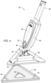
- the device 20 includes a handle or pole 22.
- the pole 22 has a handle end 24, which can include one or more actuators 26 and/or pole connectors 28. In some embodiments, there may be one or more additional actuators (not shown) on the device 20, such as on a housing 36 for example.
- the pole 22 may be extendable in a similar manner to that described in commonly-owned United States Patent Application Serial No. 16/032,846 entitled “Hard Surface Cleaning Devices" filed on July 11, 2018 , the contents of which is incorporated by reference herein.
- the pole 22 is coupled to a dispensing section 30.
- the pole 22 includes a lock member 32 and the dispensing section 30 includes a locking opening 34. The engagement of the lock member 32 in the locking opening 34 secures the pole 22 to the dispensing section 30.
- the dispensing section 30 includes the housing 36. As will be discussed in more detail herein, the housing 36 contains a cleaning fluid storage and dispensing assembly. In an embodiment, the cleaning fluid storage and dispensing assembly is operably coupled to the actuator 26 and any other actuators on the device 20 for causing the cleaning fluid storage and dispensing assembly to dispense cleaning fluid during operation.
- the dispensing section 30 is connected to a cleaning head 38 by a connector 40.
- the connector 40 may be any suitable hinged attachment that allows the head 38 to rotate about a single or two orthogonal axis during operation.
- a cleaning element 42 couples to the head 38.
- the element 42 may connect with the head 38 via straps 44, or by other suitable means, such as a hook and loop fastener for example.
- the cleaning element 42 may be a cleaning pad made from a suitable material, such as but not limited to microfiber, cotton, wool, non-woven fibers, or any combination thereof.
- the cleaning element 42 may further include other elements, such as but not limited to brush bristles, a squeegee, a scraper, or any other cleaning element or combinations thereof.
- an adapter plate 41 FIG. 19 ) may be provided that allows the user to switch between a cleaning element 42A that uses straps 44 and a cleaning element 42 that uses hook and loop fasteners 43.
- the adapter plate 41 includes tabs 45 that couple with the cleaning head 38, such as by engaging around the edge of the cleaning head 38 with one or more snapfits.
- the adapter plate 41 also includes an opening 47 that allows cleaning fluid from the nozzles to be directed therethrough.
- the cleaning element 42A is a disposable cleaning element that is intended to be discarded.
- the cleaning element 42, 42A is re-usage and is washable when it accumulates debris.
- the dispensing section 30 is further fluidly coupled to the head 38 by a conduit or dispensing tube 46 that exits an outlet 48 below removable cover 50 in the housing 36.
- the tube 46 couples with a pump and provides a fluid pathway for transferring cleaning fluid to the head 38.
- the tube 46 connects with a spray nozzle 54 via an inlet 52.
- the head 38 and the cleaning element 42 each include a central opening 56, 58 respectively.
- the nozzle 54 is recessed with respect to the bottom surface of the head 38, which offsets the nozzle from the cleaning surface to facility distribution of the cleaning fluid and prevent the nozzles from being damaged during use.
- the device 20 is configured to pump cleaning fluid from container 60 to one or more spray nozzles 54 (one shown) directly onto the surface being cleaned.
- central opening 56 that is in alignment or registration with an opening 58 in the cleaning member 42, 42A (and the adapter plate 41 in some embodiments) so that spray nozzles 54 spray the cleaning fluid through the openings onto the surface being cleaned.
- head 38 defines a chamber around nozzles 54 and positions the nozzles 54 a predefined distance from the surface being cleaned.
- device 20 is configured to capture any spray of the cleaning fluid within head 38 and is particularly configured to ensure coverage of the surface being cleaned by allowing the spray from the nozzles 54 to have sufficient space, volume, or time to form larger droplets until all the chemical is on the surface being clean.
- the assembly 60 is disposed within the housing 36 and is accessed by the user via the removable cover 50. In the illustrated embodiment, the cover 50 is removed through the actuation of a latch 62.
- the assembly 60 includes a storage container 64, a pump 66 and a power source 68.
- An outlet tube 70 defines a fluid pathway from the container 64 to the pump 66.
- An outlet tube 72 defines a fluid pathway from the pump 66 to the dispensing tube 46. It should be appreciated that in some embodiments, the dispensing tube 46 and the outlet tube 72 may be a single conduit.
- the storage container 64 is made from a substantially rigid material and includes a removable cover 74.
- the cover 74 allows the container 64 to be easily refilled.
- the container 64 is made from a translucent material to allow the user to view how much cleaning solution remains in the container 64.
- the cover 74 may include a seal that engages a portion of the container 64 to prevent fluid from leaking.
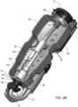
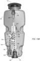
- the container 64 includes a valve assembly 92 as shown in FIGS 9A - 16 .
- the valve assembly 92 is coupled to the container housing through a tab 94 on the output cap 78.
- the container housing includes a hole on the end 76 that includes a pair of slots (not shown).
- the seal 90 is positioned on the output cap 78 and the tabs 94 interlock with the slots.
- Coupled to the output cap 78 is a valve housing 96.
- the valve housing 96 has a generally cylindrical shape with an opening 98 sized to receive the output cap 78.
- the outer diameter of the output cap 78 is press fit into the opening 98 to secure the output cap 78 to the container housing.
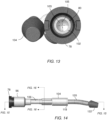
- first take-up tube 120 Coupled to an opposite side of the first tube adapter 118 is a first take-up tube 120. Coupled to the opposite end of the first take-up tube 120 is a first filter 122. It should be appreciated that a first fluid path is defined from the interior of the container 64 to the disk valve 102 by the first filter 122, first take-up tube 120, the port 116, the directional chamber 108 and the conduit 106.
- a fluid pathway may be formed between the input chamber 126 and the directional chamber 108 based on the position of the spherical member 114.
- the valve assembly 92 When the valve assembly 92 is in a first position (e.g. with the cleaning element vertically above the container 64), the spherical member 114 will move against the second inlet 110 as shown in FIG. 15C to block fluid flow from the ball valve chamber 112 to the directional chamber 108 creating a fluid pathway 123 from the filter 122 to the disk valve 102.
- the valve assembly is in a second position (e.g.
- Coupled to the input tube member 124 is a second take-up tube 132 via a second tube adapter 133. Coupled to an opposite end of the second take-up tube 132 is a second filter 134. It should be appreciated that when the valve assembly 92 is in the second position as shown in FIG. 15B (e.g. the inlets 130 are in fluid communication with the directional chamber 108), a second fluid pathway 135 is defined from the interior of the container 64 to the disk valve 102 by the second filter 134, second take-up tube 132, the input chamber 126, the passageway 128, the inlets 130, the ball valve chamber 112,through inlet 110, the directional chamber 108, and the conduit 106.
- the storage container 64 further includes one or more vents 134 that provide an air pathway from the environment to the interior of container 64.
- the vent 134 includes a slit 135 that is configured in a normally closed position (e.g. no air flow). In response to a pressure within the interior 136, falling below a threshold, a portion of the vent 134 deflects, allowing air flow into the interior 136. It should be appreciated that the vent 134 prevents the generation of low pressures (e.g. below ambient) that could interfere with the operation of the pump 66.
- valve assembly 92 When the valve assembly 92 is disposed within the interior 136 ( FIG. 9B ) of the container 64, with the pivot arm 82 coupled to the container 64, the valve assembly 92 extends along the length of the container 64 with the first filter 122 being disposed adjacent the opening 138 that is enclosed by the cap 74 and the second filter 134 being arranged adjacent the opposite end 76. As will be discussed in more detail herein, the valve assembly 92 is configured to allow the cleaning fluid storage and dispensing assembly 60 to draw cleaning fluid from the interior 136 with the device 20 positioned in any orientation (e.g. cleaning element 42 on a horizontal surface, a vertical surface, an angled surface, a floor, a wall, or a ceiling).
- any orientation e.g. cleaning element 42 on a horizontal surface, a vertical surface, an angled surface, a floor, a wall, or a ceiling.
- container 64 can be permanently connected via a tube (tether) such that no pivot arm 82 is provided.
- the tube 70 connects directly to the output cap 78 and is sized long enough so that the end user can remove the container from the housing to fill the bottle.
- the user first fills the container 64 with the desired cleaning fluid.
- the container 64 may be filled with the cleaning fluid and coupled to the pivot arm 82, or external to the device 20.
- the user installs the container 64 (if filled externally) by sliding the pivot arm 82 into the opening 80 in output cap 78.
- the seal 90 engages the inner surface of the opening 80 to both seal and secure the output cap 78 to the pivot arm 82.
- the coupling of the container 64 to the pivot arm 82 may be performed with the pivot arm 82 rotated relative to a longitudinal axis of the housing 36 or with the pivot arm 82 in the operating position.
- the pivot arm 82 can be rotated to the operating position ( FIG. 5 ) to position the container 64 within the housing 36, and the cover 50 may be installed to enclose the container 64 within the housing 36.
- the valve assembly 92 When the user positions the device 20 with the cleaning element 46 vertically below pole 22, such as when cleaning a floor or the bottom of a pane of glass from a standing position for example, the valve assembly 92 is oriented with the second filter 134 being vertically lower than the first filter 122. It should be appreciated that when in this position, the spherical member 114 is positioned with the inlets 130 in an "open" configuration to allow a fluid path from the second filter 134 to the disk valve 102. It should further be appreciated that any cleaning fluid in the container 64 will flow towards the end 76 under the influence of gravity. Thus, unless the storage container 64 is substantially filled with cleaning fluid, the first filter 122 will not be in fluid communication with the cleaning fluid, while the second filter 134 will be in fluid communication with the cleaning fluid.
- the second filter 134 may no longer be in fluid communication with the cleaning fluid since the cleaning fluid will flow to the end of the storage container 64 adjacent the cap 74. It should be appreciated that this orientation may occur when the user is cleaning a higher section of a wall or window, or the ceiling for example.
- the first filter 122 will be in fluid communication with the cleaning solution.
- the spherical member 114 will move against the inlet 110 to seal the directional chamber 108 from the ball valve chamber 112.
Landscapes
- Cleaning By Liquid Or Steam (AREA)
- Containers And Packaging Bodies Having A Special Means To Remove Contents (AREA)
Applications Claiming Priority (2)
| Application Number | Priority Date | Filing Date | Title |
|---|---|---|---|
| US16/251,769 US10973387B2 (en) | 2015-06-26 | 2019-01-18 | Multi-orientation cleaning device |
| EP20151451.0A EP3725207B1 (de) | 2019-01-18 | 2020-01-13 | Reinigungsvorrichtung mit mehreren ausrichtungen |
Related Parent Applications (1)
| Application Number | Title | Priority Date | Filing Date |
|---|---|---|---|
| EP20151451.0A Division EP3725207B1 (de) | 2019-01-18 | 2020-01-13 | Reinigungsvorrichtung mit mehreren ausrichtungen |
Publications (2)
| Publication Number | Publication Date |
|---|---|
| EP4397226A2 true EP4397226A2 (de) | 2024-07-10 |
| EP4397226A3 EP4397226A3 (de) | 2024-12-04 |
Family
ID=69159678
Family Applications (2)
| Application Number | Title | Priority Date | Filing Date |
|---|---|---|---|
| EP20151451.0A Active EP3725207B1 (de) | 2019-01-18 | 2020-01-13 | Reinigungsvorrichtung mit mehreren ausrichtungen |
| EP24169306.8A Pending EP4397226A3 (de) | 2019-01-18 | 2020-01-13 | Reinigungsvorrichtung mit mehreren ausrichtungen |
Family Applications Before (1)
| Application Number | Title | Priority Date | Filing Date |
|---|---|---|---|
| EP20151451.0A Active EP3725207B1 (de) | 2019-01-18 | 2020-01-13 | Reinigungsvorrichtung mit mehreren ausrichtungen |
Country Status (2)
| Country | Link |
|---|---|
| EP (2) | EP3725207B1 (de) |
| ES (1) | ES2978569T3 (de) |
Families Citing this family (1)
| Publication number | Priority date | Publication date | Assignee | Title |
|---|---|---|---|---|
| CN115555361B (zh) * | 2022-11-17 | 2023-03-21 | 长沙中联重科环境产业有限公司 | 垃圾桶外壁智能清洗机构及其控制方法 |
Family Cites Families (5)
| Publication number | Priority date | Publication date | Assignee | Title |
|---|---|---|---|---|
| US20030089383A1 (en) * | 2001-11-13 | 2003-05-15 | Biggs Blyth S. | Egronomic sprayer mop and method |
| US8370991B2 (en) * | 2010-09-01 | 2013-02-12 | Techtronic Floor Care Technology Limited | Supply tank assembly for an extractor cleaning machine |
| US8438696B2 (en) * | 2011-02-16 | 2013-05-14 | Techtronic Floor Care Technology Limited | Surface cleaner including a cleaning pad |
| US20140041147A1 (en) * | 2012-08-10 | 2014-02-13 | Chad Pagoria | Surface cleaner including forward-facing liquid tanks |
| DE202013009135U1 (de) * | 2013-10-16 | 2013-11-04 | Carl Freudenberg Kg | Bezug für ein Reinigungsgerät |
-
2020
- 2020-01-13 ES ES20151451T patent/ES2978569T3/es active Active
- 2020-01-13 EP EP20151451.0A patent/EP3725207B1/de active Active
- 2020-01-13 EP EP24169306.8A patent/EP4397226A3/de active Pending
Also Published As
| Publication number | Publication date |
|---|---|
| EP4397226A3 (de) | 2024-12-04 |
| ES2978569T3 (es) | 2024-09-16 |
| EP3725207A2 (de) | 2020-10-21 |
| EP3725207A3 (de) | 2020-12-02 |
| EP3725207B1 (de) | 2024-04-10 |
| EP3725207C0 (de) | 2024-04-10 |
Similar Documents
| Publication | Publication Date | Title |
|---|---|---|
| US12035863B2 (en) | Multi-orientation cleaning device | |
| CN101513629B (zh) | 耐高压加热的无桶式清洁系统 | |
| CN113243823B (zh) | 基站及表面清洁系统 | |
| JP6311892B2 (ja) | 低残留ポンプ、ディスペンサー及び詰め替えユニット | |
| CN103079444B (zh) | 用于抽吸式清洁器的供应箱组件 | |
| TWI252133B (en) | Spraying device with interchangeable cartridge | |
| US5398517A (en) | Potable water collection coil cleaning apparatus | |
| CN204210894U (zh) | 流体输送系统 | |
| US5180439A (en) | Method and apparatus for cleaning & rinsing carpets | |
| US11517924B2 (en) | Dispensing device for spraying a sprayable fluid | |
| US7448557B2 (en) | Application and method to disperse substance contained in a replaceable cartridge | |
| US12281815B2 (en) | Air treatment apparatus | |
| TW201429859A (zh) | 水平泵、再塡充單元、及具有整合空氣壓縮器之泡沫施配器 | |
| CN102641516A (zh) | 扩散管头部 | |
| US9539355B2 (en) | Aroma diffuser | |
| CN113303728B (zh) | 基站及表面清洁系统 | |
| EP3725207B1 (de) | Reinigungsvorrichtung mit mehreren ausrichtungen | |
| JP2022515898A (ja) | 空気処理装置 | |
| RU2403986C2 (ru) | Дозирующая головка для разбрызгивания жидкости из резервуара | |
| US9731330B1 (en) | Portable cooling tower cleaning system | |
| JP2005214600A (ja) | 空気調和機の洗浄装置及び洗浄方法 | |
| US20230405620A1 (en) | Cleaning machine | |
| US20130213507A1 (en) | Adjustable attachment for dispensing apparatus | |
| CN218422913U (zh) | 用于超净工作台的清洁装置及超净工作台 | |
| CN113229755A (zh) | 地面清洁设备用水容器、地面清洁设备 |
Legal Events
| Date | Code | Title | Description |
|---|---|---|---|
| PUAI | Public reference made under article 153(3) epc to a published international application that has entered the european phase |
Free format text: ORIGINAL CODE: 0009012 |
|
| STAA | Information on the status of an ep patent application or granted ep patent |
Free format text: STATUS: THE APPLICATION HAS BEEN PUBLISHED |
|
| AC | Divisional application: reference to earlier application |
Ref document number: 3725207 Country of ref document: EP Kind code of ref document: P |
|
| AK | Designated contracting states |
Kind code of ref document: A2 Designated state(s): AL AT BE BG CH CY CZ DE DK EE ES FI FR GB GR HR HU IE IS IT LI LT LU LV MC MK MT NL NO PL PT RO RS SE SI SK SM TR |
|
| PUAL | Search report despatched |
Free format text: ORIGINAL CODE: 0009013 |
|
| AK | Designated contracting states |
Kind code of ref document: A3 Designated state(s): AL AT BE BG CH CY CZ DE DK EE ES FI FR GB GR HR HU IE IS IT LI LT LU LV MC MK MT NL NO PL PT RO RS SE SI SK SM TR |
|
| RIC1 | Information provided on ipc code assigned before grant |
Ipc: A47L 13/22 20060101AFI20241029BHEP |
|
| STAA | Information on the status of an ep patent application or granted ep patent |
Free format text: STATUS: REQUEST FOR EXAMINATION WAS MADE |
|
| 17P | Request for examination filed |
Effective date: 20250604 |
|
| STAA | Information on the status of an ep patent application or granted ep patent |
Free format text: STATUS: EXAMINATION IS IN PROGRESS |
|
| 17Q | First examination report despatched |
Effective date: 20260319 |