EP4396456B1 - Auget d'une turbine pelton et son procédé de production - Google Patents
Auget d'une turbine pelton et son procédé de production Download PDFInfo
- Publication number
- EP4396456B1 EP4396456B1 EP22730477.1A EP22730477A EP4396456B1 EP 4396456 B1 EP4396456 B1 EP 4396456B1 EP 22730477 A EP22730477 A EP 22730477A EP 4396456 B1 EP4396456 B1 EP 4396456B1
- Authority
- EP
- European Patent Office
- Prior art keywords
- substrate
- coating
- tip
- depression
- cutting edge
- Prior art date
- Legal status (The legal status is an assumption and is not a legal conclusion. Google has not performed a legal analysis and makes no representation as to the accuracy of the status listed.)
- Active
Links
Images

Classifications
-
- F—MECHANICAL ENGINEERING; LIGHTING; HEATING; WEAPONS; BLASTING
- F03—MACHINES OR ENGINES FOR LIQUIDS; WIND, SPRING, OR WEIGHT MOTORS; PRODUCING MECHANICAL POWER OR A REACTIVE PROPULSIVE THRUST, NOT OTHERWISE PROVIDED FOR
- F03B—MACHINES OR ENGINES FOR LIQUIDS
- F03B1/00—Engines of impulse type, i.e. turbines with jets of high-velocity liquid impinging on blades or like rotors, e.g. Pelton wheels; Parts or details peculiar thereto
- F03B1/02—Buckets; Bucket-carrying rotors
-
- F—MECHANICAL ENGINEERING; LIGHTING; HEATING; WEAPONS; BLASTING
- F03—MACHINES OR ENGINES FOR LIQUIDS; WIND, SPRING, OR WEIGHT MOTORS; PRODUCING MECHANICAL POWER OR A REACTIVE PROPULSIVE THRUST, NOT OTHERWISE PROVIDED FOR
- F03B—MACHINES OR ENGINES FOR LIQUIDS
- F03B3/00—Machines or engines of reaction type; Parts or details peculiar thereto
- F03B3/12—Blades; Blade-carrying rotors
- F03B3/121—Blades, their form or construction
-
- F—MECHANICAL ENGINEERING; LIGHTING; HEATING; WEAPONS; BLASTING
- F05—INDEXING SCHEMES RELATING TO ENGINES OR PUMPS IN VARIOUS SUBCLASSES OF CLASSES F01-F04
- F05B—INDEXING SCHEME RELATING TO WIND, SPRING, WEIGHT, INERTIA OR LIKE MOTORS, TO MACHINES OR ENGINES FOR LIQUIDS COVERED BY SUBCLASSES F03B, F03D AND F03G
- F05B2230/00—Manufacture
- F05B2230/90—Coating; Surface treatment
-
- F—MECHANICAL ENGINEERING; LIGHTING; HEATING; WEAPONS; BLASTING
- F05—INDEXING SCHEMES RELATING TO ENGINES OR PUMPS IN VARIOUS SUBCLASSES OF CLASSES F01-F04
- F05B—INDEXING SCHEME RELATING TO WIND, SPRING, WEIGHT, INERTIA OR LIKE MOTORS, TO MACHINES OR ENGINES FOR LIQUIDS COVERED BY SUBCLASSES F03B, F03D AND F03G
- F05B2280/00—Materials; Properties thereof
- F05B2280/60—Properties or characteristics given to material by treatment or manufacturing
- F05B2280/6011—Coating
Definitions
- the present invention relates to a Pelton turbine with increased durability and a method for manufacturing the turbine.
- the present invention relates to the buckets of the turbine with a coated substrate and a method for providing and coating the substrate.
- Erosion-resistant coatings are often used on hydropower turbine components, especially on Pelton turbine impellers, which are susceptible to erosion by sediments contained in the turbine water.
- the EP 3 647 585 B1 a component of a hydroelectric turbine comprising a wedge-shaped substrate having a tip portion and at least two side portions, wherein an erosion-resistant coating is applied to the wedge-shaped substrate, and wherein the erosion-resistant coating applied to the tip portion is at least 2 times stronger than the erosion-resistant coating applied to the side portions, and wherein the erosion-resistant coating comprises at least 99.5% density.
- the application of the erosion-resistant coating is carried out by the high-velocity air-fuel process (HVAF).
- HVAF high-velocity air-fuel process
- the EP 3 647 585 B1 Buckets of a Pelton turbine runner which are constructed in this way.
- the object of the invention is to provide an impeller of a Pelton type turbine which has an alternative structure and is manufactured by an alternative method, wherein the resistance of the impeller to erosion is comparably high as the resistance of the impellers known from the prior art.
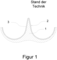
- FIG 1 shows a section through a bucket of a Pelton type turbine in a schematic representation according to the state of the art.
- the bucket comprises a substrate which is designated with 1.
- the substrate is made of steel.
- the main cutting edge which is designated with 2, is arranged centrally in the bucket.
- the main cutting edge splits the water jet directed onto the turbine into two partial jets, which are deflected by the two halves of the bucket.
- the main cutting edge is therefore also often referred to as a "splitter”.
- the Figure 1 The cut shown runs perpendicular to the direction of the main cutting edge.
- the inside of the cup is coated with an erosion-resistant coating, which is marked with 3.
- the substrate already has essentially the same contour as the coated cup.
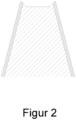
- Figure 2 shows the main cutting edge 2 degraded by erosion from Figure 1 . Since the abrasion is strongest at the tip of the cutting edge, which is hit by the undivided water jet, the coating is removed there first and then the substrate underneath. The coating remaining on the flanks is removed less quickly than the substrate, so that a characteristic groove is formed. It is clear that such a profile of the main cutting edge leads to considerable losses in efficiency, so that an impeller that is degraded in this way must be replaced.
- the described degradation process can be slowed down by providing as much resistant material as possible at the point of the strongest abrasion.
- This is achieved by ensuring that the erosion resistant coating applied to the tip section is at least 2 times thicker than the erosion resistant coating applied to the side sections.
- An undesirable side effect of this is that the tip radius on the main cutting edge is increased, which leads to a reduced initial efficiency of the turbine.
- the inventors therefore looked for a way to arrange as much resistant material as possible at the point of greatest stress without the tip radius increasing accordingly. They realized that this can be achieved by giving the substrate a contour before coating that resembles the contour of a degraded cup (see Figure 2 ) corresponds.
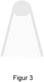
- Figure 3 shows the main cutting edge of a cup according to the invention.
- the substrate has a wedge-shaped form in the area of the main cutting edge, whereby the end of the wedge does not end in a single tip, but rather there is a depression or groove arranged between two tips at this point.
- the wedge-shaped substrate comprises a first and a second tip section and a total of four side sections in the area of the main cutting edge, whereby a depression extends between the tip sections, whereby two side sections are assigned to each tip section, and whereby two of the side sections are arranged on the outside of the wedge-shaped substrate, and the two remaining side sections are oriented towards the depression on the inside.
- the lines formed by the end points of the two tip sections run parallel to the cutting line of the main cutting edge.
- the depression forms a "valley" between the tip sections, so to speak.
- the depression is first filled with erosion-resistant material.
- the coating process is then carried out in This process is continued in this area until the coating material has formed a raised area there in order to form the tip of the main cutting edge.
- the surface of the coating in the area of the deepest point of the depression must protrude at least slightly above the surface of the coating on the two tip sections.
- the outer side sections and the rest of the Pelton cup are then coated. The outer side sections and the rest of the Pelton cup could just as well be coated first, ie before coating the depression as described above.
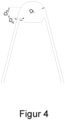
- Figure 4 shows the main cutting edge according to the invention, with certain characteristic dimensions being marked. These dimensions relate to the layer thickness of the coating at certain points on the substrate, with the thickness of the coating being measured in a direction perpendicular to the substrate surface at the relevant point.
- D A indicates the thickness of the coating in the area of an outer side section.
- D I indicates the thickness of the coating in the area of an inner side section.
- Ds indicates the thickness of the coating at a tip section.
- a main cutting edge according to the invention is characterized in that the following relation is fulfilled for the thicknesses of the coating mentioned: D A ⁇ D S ⁇ D I
- Typical layer thicknesses in the area of the outer side sections are in the range of 0.3 mm ⁇ D A ⁇ 0.7 mm.
- Figure 5 shows the main cutting edge according to the invention, with certain further characteristic dimensions being marked.
- W is the distance between the two tip sections of the substrate, this distance being perpendicular to the axis of symmetry of the cutting edge and perpendicular to the cutting line.
- H is the height of the tip sections in relation to the deepest point of the recess. H is removed parallel to the axis of symmetry of the cutting edge.
- D is the thickness of the coating at the point where the axis of symmetry of the main cutting edge intersects the substrate, ie in the middle of the recess, which usually has its deepest point there.
- the exact shape of the recess is not crucial. The easiest way to do this is to mill such a recess into the substrate, e.g. with a cove milling cutter.
- the erosion-resistant coating is applied.
- suitable materials and compositions of the erosion-resistant coating see sections [0027] and [0028] of the EP 3 647 585 B1
- the combination of tungsten carbide particles with a matrix of CoCr is considered to be particularly suitable.
- the coating can be carried out using HVOF or HVAF. HVOF is considered to be particularly suitable. Details of these processes can be found in the EP 3 647 585 B1 be taken.
- step S1 must be carried out before steps S2 and S3.
- the order of steps S2 and S3 can then be arbitrary.
- the coating process described can be carried out on separate buckets when the buckets are attached as a whole to a hub during the manufacture of a Pelton impeller.
- the coating process described is carried out when the entire bucket is on the hub.
Landscapes
- Engineering & Computer Science (AREA)
- Chemical & Material Sciences (AREA)
- Combustion & Propulsion (AREA)
- Mechanical Engineering (AREA)
- General Engineering & Computer Science (AREA)
- Turbine Rotor Nozzle Sealing (AREA)
Claims (6)
- Gobelet d'une turbine du type Pelton comprenant un substrat (1), une arête de coupe principale (2) et un revêtement (3) résistant à l'érosion recouvrant le substrat (1), le substrat (1) présentant dans la zone de l'arête de coupe principale (2) une forme cunéiforme, caractérisé en ce que le substrat (1) comprend dans la zone de l'arête de coupe principale (2) une première et une deuxième partie de pointe et au total quatre parties latérales, un creux s'étendant entre les parties de pointe, et deux sections latérales étant associées à chaque partie de pointe, et deux des parties latérales étant disposées à l'extérieur du substrat en forme de coin, et les deux parties latérales restantes étant orientées vers l'intérieur en direction du creux, et le revêtement (3) formant une surélévation dans la zone du creux afin de former la pointe de l'arête de coupe principale (2).
- Gobelet selon la revendication 1, dans lequel les deux parties de pointe sont disposées de telle sorte qu'elles présentent une distance W de 3 à 7 mm.
- Gobelet selon la revendication 1 ou 2, dans lequel les deux parties de pointe et le creux sont formés de telle sorte que les parties de pointe ont une hauteur H par rapport à un point le plus bas du creux qui est comprise entre 0,1 mm et 0,7 mm.
- Gobelet selon l'une quelconque des revendications précédentes, dans lequel le revêtement (3) présente une épaisseur D d'au moins 1 mm au centre de la cavité.
- Gobelet selon l'une quelconque des revendications précédentes, dans lequel le revêtement (3) est constitué d'une matrice de CoCr dans laquelle sont noyées des particules de carbure de tungstène.
- Procédé de fabrication d'un gobelet de turbine de type Pelton selon l'une quelconque des revendications précédentes, ledit procédé comprenant les étapes suivantes :S1 : fourniture d'un substrat (1) comportant un creux situé entre deux parties de pointe et dans lequel deux parties latérales sont situées à l'extérieur des parties de pointe ;S2 : Application d'un revêtement résistant à l'érosion (3) sur le substrat (1) dans la zone de la cavité, celle-ci étant remplie de matériau résistant à l'érosion et l'opération de revêtement étant ensuite poursuivie dans cette zone jusqu'à ce que le matériau de revêtement y ait formé une surélévation ;S3 : Application d'un revêtement résistant à l'érosion (3) sur le substrat (1) dans la zone des parties latérales extérieures.
Applications Claiming Priority (2)
| Application Number | Priority Date | Filing Date | Title |
|---|---|---|---|
| DE102021122700 | 2021-09-02 | ||
| PCT/EP2022/064163 WO2023030704A1 (fr) | 2021-09-02 | 2022-05-25 | Auget d'une turbine pelton et son procédé de production |
Publications (2)
| Publication Number | Publication Date |
|---|---|
| EP4396456A1 EP4396456A1 (fr) | 2024-07-10 |
| EP4396456B1 true EP4396456B1 (fr) | 2024-12-04 |
Family
ID=82058267
Family Applications (1)
| Application Number | Title | Priority Date | Filing Date |
|---|---|---|---|
| EP22730477.1A Active EP4396456B1 (fr) | 2021-09-02 | 2022-05-25 | Auget d'une turbine pelton et son procédé de production |
Country Status (6)
| Country | Link |
|---|---|
| EP (1) | EP4396456B1 (fr) |
| CN (1) | CN117916460A (fr) |
| CL (1) | CL2024000606A1 (fr) |
| CO (1) | CO2024001990A2 (fr) |
| PE (1) | PE20240870A1 (fr) |
| WO (1) | WO2023030704A1 (fr) |
Family Cites Families (4)
| Publication number | Priority date | Publication date | Assignee | Title |
|---|---|---|---|---|
| JP2001153019A (ja) * | 1999-11-30 | 2001-06-05 | Toshiba Corp | ペルトン水車のバケット、ニードル弁及びペルトン水車 |
| EP2072176A1 (fr) * | 2007-12-21 | 2009-06-24 | Sulzer Markets and Technology AG | Procédé destiné à la fabrication d'une couche de protection à base d'acier contre l'érosion utilisant le laser; Composant comprenant une telle couche de protection à base d'acier contre l'érosion |
| FR2941639B1 (fr) * | 2009-01-30 | 2012-04-20 | Alstom Hydro France | Composant neuf de machine hydraulique, procede de fabrication ou de maintenance d'un tel composant |
| EP3647585B1 (fr) | 2018-11-02 | 2021-04-28 | GE Renewable Technologies | Composant de turbine hydro-électrique ayant une durée de vie accrue et son procédé de fabrication |
-
2022
- 2022-05-25 CN CN202280059254.3A patent/CN117916460A/zh active Pending
- 2022-05-25 PE PE2024000297A patent/PE20240870A1/es unknown
- 2022-05-25 WO PCT/EP2022/064163 patent/WO2023030704A1/fr not_active Ceased
- 2022-05-25 EP EP22730477.1A patent/EP4396456B1/fr active Active
-
2024
- 2024-02-22 CO CONC2024/0001990A patent/CO2024001990A2/es unknown
- 2024-02-28 CL CL2024000606A patent/CL2024000606A1/es unknown
Also Published As
| Publication number | Publication date |
|---|---|
| WO2023030704A1 (fr) | 2023-03-09 |
| PE20240870A1 (es) | 2024-04-24 |
| CN117916460A (zh) | 2024-04-19 |
| CO2024001990A2 (es) | 2024-03-07 |
| EP4396456A1 (fr) | 2024-07-10 |
| CL2024000606A1 (es) | 2024-08-09 |
Similar Documents
| Publication | Publication Date | Title |
|---|---|---|
| DE3045224C2 (fr) | ||
| DE69604154T2 (de) | Abreibbare spaltabdichtung für turbomaschinen | |
| DE4436186A1 (de) | Verfahren und Vorrichtung zum Reduzieren von Spannungen an der Spitze von Turbinen- oder Kompressorschaufeln | |
| EP2372093B1 (fr) | Forme du joint d'étanchéité sur la plateforme d'une aube de turbine | |
| EP2044240B1 (fr) | Procédé d'application d'un matériau de revêtement et revêtement pour une surface métallique | |
| DE69116440T2 (de) | Verfahren zur Reparatur von Turbinen | |
| EP3093372A2 (fr) | Procede de recouvrement destine a produire une combinaison de blindage d'extremite d'aubes et couche de protection contre l'erosion | |
| DE19857653C2 (de) | Laufschaufel einer mehrstufigen Dampfturbine | |
| DE2004724A1 (de) | Turbinenschaufel | |
| DE602004003757T2 (de) | Verfahren zur Aufbereitung und Verfahren zur Herstellung einer Turbinenschaufel | |
| EP4396456B1 (fr) | Auget d'une turbine pelton et son procédé de production | |
| EP3246430A1 (fr) | Procédé de fabrication d'aubes ou de système d'aubes d'une turbomachine comprenant des couches de protection contre l'érosion et composant ainsi fabriqué | |
| DE102010031213A1 (de) | Rotor einer Turbomaschine | |
| DE102007029992A1 (de) | Kolbenring | |
| EP3460187A1 (fr) | Aube pour une turbomachine | |
| DE102016116815A1 (de) | Verfahren zur Beschichtung eines Zylinders einer Verbrennungskraftmaschine und Zylinder für eine Verbrennungskraftmaschine | |
| EP2087149A2 (fr) | Aube pour compresseur ou turbine d'un turboréacteur, turboréacteur présentant une telle aube, et procédé de recouvrement d'une aube de turboréacteur | |
| DE102022132483B3 (de) | Verfahren zur Herstellung einer Laufschaufel | |
| EP4381187B1 (fr) | Élément d'une turbine hydroélectrique et procédé de production | |
| EP2639004B1 (fr) | Segment de couronne d'aubes avec surface de limitation de l'espace annulaire à profil en hauteur ondulé et procédé de fabrication | |
| DE1426780A1 (de) | Turbinenlaeufer | |
| DE102009052883A1 (de) | Kopplungselement zur mechanischen Kopplung von Schaufeln und Rotor | |
| EP2094997B1 (fr) | Piston pour un moteur thermique | |
| DE102024100709B3 (de) | Laufradschaufel für eine hydraulische Maschine einer Wasserkraftanlage | |
| EP3015652A1 (fr) | Aube mobile de turbine |
Legal Events
| Date | Code | Title | Description |
|---|---|---|---|
| STAA | Information on the status of an ep patent application or granted ep patent |
Free format text: STATUS: UNKNOWN |
|
| STAA | Information on the status of an ep patent application or granted ep patent |
Free format text: STATUS: THE INTERNATIONAL PUBLICATION HAS BEEN MADE |
|
| PUAI | Public reference made under article 153(3) epc to a published international application that has entered the european phase |
Free format text: ORIGINAL CODE: 0009012 |
|
| STAA | Information on the status of an ep patent application or granted ep patent |
Free format text: STATUS: REQUEST FOR EXAMINATION WAS MADE |
|
| 17P | Request for examination filed |
Effective date: 20240402 |
|
| AK | Designated contracting states |
Kind code of ref document: A1 Designated state(s): AL AT BE BG CH CY CZ DE DK EE ES FI FR GB GR HR HU IE IS IT LI LT LU LV MC MK MT NL NO PL PT RO RS SE SI SK SM TR |
|
| GRAP | Despatch of communication of intention to grant a patent |
Free format text: ORIGINAL CODE: EPIDOSNIGR1 |
|
| STAA | Information on the status of an ep patent application or granted ep patent |
Free format text: STATUS: GRANT OF PATENT IS INTENDED |
|
| GRAS | Grant fee paid |
Free format text: ORIGINAL CODE: EPIDOSNIGR3 |
|
| GRAA | (expected) grant |
Free format text: ORIGINAL CODE: 0009210 |
|
| STAA | Information on the status of an ep patent application or granted ep patent |
Free format text: STATUS: THE PATENT HAS BEEN GRANTED |
|
| DAV | Request for validation of the european patent (deleted) | ||
| DAX | Request for extension of the european patent (deleted) | ||
| INTG | Intention to grant announced |
Effective date: 20241024 |
|
| AK | Designated contracting states |
Kind code of ref document: B1 Designated state(s): AL AT BE BG CH CY CZ DE DK EE ES FI FR GB GR HR HU IE IS IT LI LT LU LV MC MK MT NL NO PL PT RO RS SE SI SK SM TR |
|
| REG | Reference to a national code |
Ref country code: CH Ref legal event code: EP |
|
| REG | Reference to a national code |
Ref country code: DE Ref legal event code: R096 Ref document number: 502022002321 Country of ref document: DE |
|
| REG | Reference to a national code |
Ref country code: IE Ref legal event code: FG4D Free format text: LANGUAGE OF EP DOCUMENT: GERMAN |
|
| REG | Reference to a national code |
Ref country code: LT Ref legal event code: MG9D |
|
| REG | Reference to a national code |
Ref country code: NL Ref legal event code: MP Effective date: 20241204 |
|
| PG25 | Lapsed in a contracting state [announced via postgrant information from national office to epo] |
Ref country code: HR Free format text: LAPSE BECAUSE OF FAILURE TO SUBMIT A TRANSLATION OF THE DESCRIPTION OR TO PAY THE FEE WITHIN THE PRESCRIBED TIME-LIMIT Effective date: 20241204 |
|
| PG25 | Lapsed in a contracting state [announced via postgrant information from national office to epo] |
Ref country code: FI Free format text: LAPSE BECAUSE OF FAILURE TO SUBMIT A TRANSLATION OF THE DESCRIPTION OR TO PAY THE FEE WITHIN THE PRESCRIBED TIME-LIMIT Effective date: 20241204 |
|
| PG25 | Lapsed in a contracting state [announced via postgrant information from national office to epo] |
Ref country code: BG Free format text: LAPSE BECAUSE OF FAILURE TO SUBMIT A TRANSLATION OF THE DESCRIPTION OR TO PAY THE FEE WITHIN THE PRESCRIBED TIME-LIMIT Effective date: 20241204 |
|
| PG25 | Lapsed in a contracting state [announced via postgrant information from national office to epo] |
Ref country code: ES Free format text: LAPSE BECAUSE OF FAILURE TO SUBMIT A TRANSLATION OF THE DESCRIPTION OR TO PAY THE FEE WITHIN THE PRESCRIBED TIME-LIMIT Effective date: 20241204 |
|
| PG25 | Lapsed in a contracting state [announced via postgrant information from national office to epo] |
Ref country code: NO Free format text: LAPSE BECAUSE OF FAILURE TO SUBMIT A TRANSLATION OF THE DESCRIPTION OR TO PAY THE FEE WITHIN THE PRESCRIBED TIME-LIMIT Effective date: 20250304 |
|
| PG25 | Lapsed in a contracting state [announced via postgrant information from national office to epo] |
Ref country code: LV Free format text: LAPSE BECAUSE OF FAILURE TO SUBMIT A TRANSLATION OF THE DESCRIPTION OR TO PAY THE FEE WITHIN THE PRESCRIBED TIME-LIMIT Effective date: 20241204 Ref country code: GR Free format text: LAPSE BECAUSE OF FAILURE TO SUBMIT A TRANSLATION OF THE DESCRIPTION OR TO PAY THE FEE WITHIN THE PRESCRIBED TIME-LIMIT Effective date: 20250305 |
|
| PG25 | Lapsed in a contracting state [announced via postgrant information from national office to epo] |
Ref country code: RS Free format text: LAPSE BECAUSE OF FAILURE TO SUBMIT A TRANSLATION OF THE DESCRIPTION OR TO PAY THE FEE WITHIN THE PRESCRIBED TIME-LIMIT Effective date: 20250304 |
|
| PG25 | Lapsed in a contracting state [announced via postgrant information from national office to epo] |
Ref country code: NL Free format text: LAPSE BECAUSE OF FAILURE TO SUBMIT A TRANSLATION OF THE DESCRIPTION OR TO PAY THE FEE WITHIN THE PRESCRIBED TIME-LIMIT Effective date: 20241204 |
|
| PG25 | Lapsed in a contracting state [announced via postgrant information from national office to epo] |
Ref country code: SM Free format text: LAPSE BECAUSE OF FAILURE TO SUBMIT A TRANSLATION OF THE DESCRIPTION OR TO PAY THE FEE WITHIN THE PRESCRIBED TIME-LIMIT Effective date: 20241204 |
|
| PG25 | Lapsed in a contracting state [announced via postgrant information from national office to epo] |
Ref country code: PL Free format text: LAPSE BECAUSE OF FAILURE TO SUBMIT A TRANSLATION OF THE DESCRIPTION OR TO PAY THE FEE WITHIN THE PRESCRIBED TIME-LIMIT Effective date: 20241204 |
|
| PGFP | Annual fee paid to national office [announced via postgrant information from national office to epo] |
Ref country code: DE Payment date: 20250521 Year of fee payment: 4 |
|
| PG25 | Lapsed in a contracting state [announced via postgrant information from national office to epo] |
Ref country code: IS Free format text: LAPSE BECAUSE OF FAILURE TO SUBMIT A TRANSLATION OF THE DESCRIPTION OR TO PAY THE FEE WITHIN THE PRESCRIBED TIME-LIMIT Effective date: 20250404 |
|
| PG25 | Lapsed in a contracting state [announced via postgrant information from national office to epo] |
Ref country code: PT Free format text: LAPSE BECAUSE OF FAILURE TO SUBMIT A TRANSLATION OF THE DESCRIPTION OR TO PAY THE FEE WITHIN THE PRESCRIBED TIME-LIMIT Effective date: 20250404 |
|
| PG25 | Lapsed in a contracting state [announced via postgrant information from national office to epo] |
Ref country code: EE Free format text: LAPSE BECAUSE OF FAILURE TO SUBMIT A TRANSLATION OF THE DESCRIPTION OR TO PAY THE FEE WITHIN THE PRESCRIBED TIME-LIMIT Effective date: 20241204 |
|
| PGFP | Annual fee paid to national office [announced via postgrant information from national office to epo] |
Ref country code: FR Payment date: 20250528 Year of fee payment: 4 |
|
| PGFP | Annual fee paid to national office [announced via postgrant information from national office to epo] |
Ref country code: CH Payment date: 20250601 Year of fee payment: 4 |
|
| PG25 | Lapsed in a contracting state [announced via postgrant information from national office to epo] |
Ref country code: RO Free format text: LAPSE BECAUSE OF FAILURE TO SUBMIT A TRANSLATION OF THE DESCRIPTION OR TO PAY THE FEE WITHIN THE PRESCRIBED TIME-LIMIT Effective date: 20241204 |
|
| PGFP | Annual fee paid to national office [announced via postgrant information from national office to epo] |
Ref country code: AT Payment date: 20250721 Year of fee payment: 4 |
|
| PG25 | Lapsed in a contracting state [announced via postgrant information from national office to epo] |
Ref country code: SK Free format text: LAPSE BECAUSE OF FAILURE TO SUBMIT A TRANSLATION OF THE DESCRIPTION OR TO PAY THE FEE WITHIN THE PRESCRIBED TIME-LIMIT Effective date: 20241204 |
|
| PG25 | Lapsed in a contracting state [announced via postgrant information from national office to epo] |
Ref country code: CZ Free format text: LAPSE BECAUSE OF FAILURE TO SUBMIT A TRANSLATION OF THE DESCRIPTION OR TO PAY THE FEE WITHIN THE PRESCRIBED TIME-LIMIT Effective date: 20241204 |
|
| PG25 | Lapsed in a contracting state [announced via postgrant information from national office to epo] |
Ref country code: IT Free format text: LAPSE BECAUSE OF FAILURE TO SUBMIT A TRANSLATION OF THE DESCRIPTION OR TO PAY THE FEE WITHIN THE PRESCRIBED TIME-LIMIT Effective date: 20241204 |
|
| REG | Reference to a national code |
Ref country code: DE Ref legal event code: R097 Ref document number: 502022002321 Country of ref document: DE |
|
| PG25 | Lapsed in a contracting state [announced via postgrant information from national office to epo] |
Ref country code: SE Free format text: LAPSE BECAUSE OF FAILURE TO SUBMIT A TRANSLATION OF THE DESCRIPTION OR TO PAY THE FEE WITHIN THE PRESCRIBED TIME-LIMIT Effective date: 20241204 |
|
| PG25 | Lapsed in a contracting state [announced via postgrant information from national office to epo] |
Ref country code: DK Free format text: LAPSE BECAUSE OF FAILURE TO SUBMIT A TRANSLATION OF THE DESCRIPTION OR TO PAY THE FEE WITHIN THE PRESCRIBED TIME-LIMIT Effective date: 20241204 |
|
| PLBE | No opposition filed within time limit |
Free format text: ORIGINAL CODE: 0009261 |
|
| STAA | Information on the status of an ep patent application or granted ep patent |
Free format text: STATUS: NO OPPOSITION FILED WITHIN TIME LIMIT |
|
| 26N | No opposition filed |
Effective date: 20250905 |
|
| PG25 | Lapsed in a contracting state [announced via postgrant information from national office to epo] |
Ref country code: LU Free format text: LAPSE BECAUSE OF NON-PAYMENT OF DUE FEES Effective date: 20250525 |
|
| PG25 | Lapsed in a contracting state [announced via postgrant information from national office to epo] |
Ref country code: MC Free format text: LAPSE BECAUSE OF FAILURE TO SUBMIT A TRANSLATION OF THE DESCRIPTION OR TO PAY THE FEE WITHIN THE PRESCRIBED TIME-LIMIT Effective date: 20241204 |