EP4396456B1 - Becher einer turbine vom typ pelton und verfahren zur herstellung - Google Patents
Becher einer turbine vom typ pelton und verfahren zur herstellung Download PDFInfo
- Publication number
- EP4396456B1 EP4396456B1 EP22730477.1A EP22730477A EP4396456B1 EP 4396456 B1 EP4396456 B1 EP 4396456B1 EP 22730477 A EP22730477 A EP 22730477A EP 4396456 B1 EP4396456 B1 EP 4396456B1
- Authority
- EP
- European Patent Office
- Prior art keywords
- substrate
- coating
- tip
- depression
- cutting edge
- Prior art date
- Legal status (The legal status is an assumption and is not a legal conclusion. Google has not performed a legal analysis and makes no representation as to the accuracy of the status listed.)
- Active
Links
Images


Classifications
-
- F—MECHANICAL ENGINEERING; LIGHTING; HEATING; WEAPONS; BLASTING
- F03—MACHINES OR ENGINES FOR LIQUIDS; WIND, SPRING, OR WEIGHT MOTORS; PRODUCING MECHANICAL POWER OR A REACTIVE PROPULSIVE THRUST, NOT OTHERWISE PROVIDED FOR
- F03B—MACHINES OR ENGINES FOR LIQUIDS
- F03B1/00—Engines of impulse type, i.e. turbines with jets of high-velocity liquid impinging on blades or like rotors, e.g. Pelton wheels; Parts or details peculiar thereto
- F03B1/02—Buckets; Bucket-carrying rotors
-
- F—MECHANICAL ENGINEERING; LIGHTING; HEATING; WEAPONS; BLASTING
- F03—MACHINES OR ENGINES FOR LIQUIDS; WIND, SPRING, OR WEIGHT MOTORS; PRODUCING MECHANICAL POWER OR A REACTIVE PROPULSIVE THRUST, NOT OTHERWISE PROVIDED FOR
- F03B—MACHINES OR ENGINES FOR LIQUIDS
- F03B3/00—Machines or engines of reaction type; Parts or details peculiar thereto
- F03B3/12—Blades; Blade-carrying rotors
- F03B3/121—Blades, their form or construction
-
- F—MECHANICAL ENGINEERING; LIGHTING; HEATING; WEAPONS; BLASTING
- F05—INDEXING SCHEMES RELATING TO ENGINES OR PUMPS IN VARIOUS SUBCLASSES OF CLASSES F01-F04
- F05B—INDEXING SCHEME RELATING TO WIND, SPRING, WEIGHT, INERTIA OR LIKE MOTORS, TO MACHINES OR ENGINES FOR LIQUIDS COVERED BY SUBCLASSES F03B, F03D AND F03G
- F05B2230/00—Manufacture
- F05B2230/90—Coating; Surface treatment
-
- F—MECHANICAL ENGINEERING; LIGHTING; HEATING; WEAPONS; BLASTING
- F05—INDEXING SCHEMES RELATING TO ENGINES OR PUMPS IN VARIOUS SUBCLASSES OF CLASSES F01-F04
- F05B—INDEXING SCHEME RELATING TO WIND, SPRING, WEIGHT, INERTIA OR LIKE MOTORS, TO MACHINES OR ENGINES FOR LIQUIDS COVERED BY SUBCLASSES F03B, F03D AND F03G
- F05B2280/00—Materials; Properties thereof
- F05B2280/60—Properties or characteristics given to material by treatment or manufacturing
- F05B2280/6011—Coating
Definitions
- the present invention relates to a Pelton turbine with increased durability and a method for manufacturing the turbine.
- the present invention relates to the buckets of the turbine with a coated substrate and a method for providing and coating the substrate.
- Erosion-resistant coatings are often used on hydropower turbine components, especially on Pelton turbine impellers, which are susceptible to erosion by sediments contained in the turbine water.
- the EP 3 647 585 B1 a component of a hydroelectric turbine comprising a wedge-shaped substrate having a tip portion and at least two side portions, wherein an erosion-resistant coating is applied to the wedge-shaped substrate, and wherein the erosion-resistant coating applied to the tip portion is at least 2 times stronger than the erosion-resistant coating applied to the side portions, and wherein the erosion-resistant coating comprises at least 99.5% density.
- the application of the erosion-resistant coating is carried out by the high-velocity air-fuel process (HVAF).
- HVAF high-velocity air-fuel process
- the EP 3 647 585 B1 Buckets of a Pelton turbine runner which are constructed in this way.
- the object of the invention is to provide an impeller of a Pelton type turbine which has an alternative structure and is manufactured by an alternative method, wherein the resistance of the impeller to erosion is comparably high as the resistance of the impellers known from the prior art.
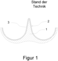
- FIG 1 shows a section through a bucket of a Pelton type turbine in a schematic representation according to the state of the art.
- the bucket comprises a substrate which is designated with 1.
- the substrate is made of steel.
- the main cutting edge which is designated with 2, is arranged centrally in the bucket.
- the main cutting edge splits the water jet directed onto the turbine into two partial jets, which are deflected by the two halves of the bucket.
- the main cutting edge is therefore also often referred to as a "splitter”.
- the Figure 1 The cut shown runs perpendicular to the direction of the main cutting edge.
- the inside of the cup is coated with an erosion-resistant coating, which is marked with 3.
- the substrate already has essentially the same contour as the coated cup.
- Figure 2 shows the main cutting edge 2 degraded by erosion from Figure 1 . Since the abrasion is strongest at the tip of the cutting edge, which is hit by the undivided water jet, the coating is removed there first and then the substrate underneath. The coating remaining on the flanks is removed less quickly than the substrate, so that a characteristic groove is formed. It is clear that such a profile of the main cutting edge leads to considerable losses in efficiency, so that an impeller that is degraded in this way must be replaced.
- the described degradation process can be slowed down by providing as much resistant material as possible at the point of the strongest abrasion.
- This is achieved by ensuring that the erosion resistant coating applied to the tip section is at least 2 times thicker than the erosion resistant coating applied to the side sections.
- An undesirable side effect of this is that the tip radius on the main cutting edge is increased, which leads to a reduced initial efficiency of the turbine.
- the inventors therefore looked for a way to arrange as much resistant material as possible at the point of greatest stress without the tip radius increasing accordingly. They realized that this can be achieved by giving the substrate a contour before coating that resembles the contour of a degraded cup (see Figure 2 ) corresponds.
- Figure 3 shows the main cutting edge of a cup according to the invention.
- the substrate has a wedge-shaped form in the area of the main cutting edge, whereby the end of the wedge does not end in a single tip, but rather there is a depression or groove arranged between two tips at this point.
- the wedge-shaped substrate comprises a first and a second tip section and a total of four side sections in the area of the main cutting edge, whereby a depression extends between the tip sections, whereby two side sections are assigned to each tip section, and whereby two of the side sections are arranged on the outside of the wedge-shaped substrate, and the two remaining side sections are oriented towards the depression on the inside.
- the lines formed by the end points of the two tip sections run parallel to the cutting line of the main cutting edge.
- the depression forms a "valley" between the tip sections, so to speak.
- the depression is first filled with erosion-resistant material.
- the coating process is then carried out in This process is continued in this area until the coating material has formed a raised area there in order to form the tip of the main cutting edge.
- the surface of the coating in the area of the deepest point of the depression must protrude at least slightly above the surface of the coating on the two tip sections.
- the outer side sections and the rest of the Pelton cup are then coated. The outer side sections and the rest of the Pelton cup could just as well be coated first, ie before coating the depression as described above.
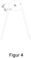
- Figure 4 shows the main cutting edge according to the invention, with certain characteristic dimensions being marked. These dimensions relate to the layer thickness of the coating at certain points on the substrate, with the thickness of the coating being measured in a direction perpendicular to the substrate surface at the relevant point.
- D A indicates the thickness of the coating in the area of an outer side section.
- D I indicates the thickness of the coating in the area of an inner side section.
- Ds indicates the thickness of the coating at a tip section.
- a main cutting edge according to the invention is characterized in that the following relation is fulfilled for the thicknesses of the coating mentioned: D A ⁇ D S ⁇ D I
- Typical layer thicknesses in the area of the outer side sections are in the range of 0.3 mm ⁇ D A ⁇ 0.7 mm.
- Figure 5 shows the main cutting edge according to the invention, with certain further characteristic dimensions being marked.
- W is the distance between the two tip sections of the substrate, this distance being perpendicular to the axis of symmetry of the cutting edge and perpendicular to the cutting line.
- H is the height of the tip sections in relation to the deepest point of the recess. H is removed parallel to the axis of symmetry of the cutting edge.
- D is the thickness of the coating at the point where the axis of symmetry of the main cutting edge intersects the substrate, ie in the middle of the recess, which usually has its deepest point there.
- the exact shape of the recess is not crucial. The easiest way to do this is to mill such a recess into the substrate, e.g. with a cove milling cutter.
- the erosion-resistant coating is applied.
- suitable materials and compositions of the erosion-resistant coating see sections [0027] and [0028] of the EP 3 647 585 B1
- the combination of tungsten carbide particles with a matrix of CoCr is considered to be particularly suitable.
- the coating can be carried out using HVOF or HVAF. HVOF is considered to be particularly suitable. Details of these processes can be found in the EP 3 647 585 B1 be taken.
- step S1 must be carried out before steps S2 and S3.
- the order of steps S2 and S3 can then be arbitrary.
- the coating process described can be carried out on separate buckets when the buckets are attached as a whole to a hub during the manufacture of a Pelton impeller.
- the coating process described is carried out when the entire bucket is on the hub.
Landscapes
- Engineering & Computer Science (AREA)
- Chemical & Material Sciences (AREA)
- Combustion & Propulsion (AREA)
- Mechanical Engineering (AREA)
- General Engineering & Computer Science (AREA)
- Turbine Rotor Nozzle Sealing (AREA)
Description
- Die vorliegende Erfindung betrifft eine Pelton-Turbine mit erhöhter Lebensdauer und ein Verfahren zur Herstellung der Turbine. Insbesondere betrifft die vorliegende Erfindung die Becher der Turbine mit einem beschichteten Substrat und ein Verfahren zur Bereitstellung und Beschichtung des Substrats.
- Erosionsbeständige Beschichtungen werden häufig auf Komponenten von Wasserkraftturbinen verwendet, insbesondere auch bei Laufrädern von Pelton-Turbinen, die anfällig für Erosion durch im Triebwasser enthaltene Sedimente sind.
- So offenbart z.B. die
EP 3 647 585 B1 ein Bauteil einer hydroelektrischen Turbine, das ein keilförmiges Substrat mit einem Spitzenabschnitt und mindestens zwei Seitenabschnitten umfasst, wobei eine erosionsbeständige Beschichtung auf dem keilförmigen Substrat aufgebracht ist, und wobei die erosionsbeständige Beschichtung, die auf dem Spitzenabschnitt aufgebracht ist, mindestens 2 Mal stärker ist als die erosionsbeständige Beschichtung, die auf den Seitenabschnitten aufgebracht ist, und wobei die erosionsbeständige Beschichtung mindestens 99,5% Dichte umfasst. Dabei erfolgt die Applikation der erosionsbeständigen Beschichtung durch den Hochgeschwindigkeits-Air-Fuel-Prozess (HVAF). Insbesondere offenbart dieEP 3 647 585 B1 Becher eines Pelton-Turbinenlaufrades, welche so aufgebaut sind. - Die Aufgabe der Erfindung ist es, ein Laufrad einer Turbine vom Typ Pelton anzugeben, das einen alternativen Aufbau aufweist, und durch ein alternatives Verfahren hergestellt wird, wobei die Beständigkeit des Laufrades gegen Erosion vergleichbar hoch ist, wie die Beständigkeit der aus dem Stand der Technik bekannten Laufräder.
- Die Aufgabe wird erfindungsgemäß durch eine Ausführung entsprechend dem unabhängigen Anspruch gelöst. Weitere vorteilhafte Ausführungsformen der vorliegenden Erfindung finden sich in den Unteransprüchen.
- Im Folgenden wird die Erfindung anhand von Figuren erläutert. Die Figuren zeigen im Einzelnen:
- Fig.1
- Becher einer Pelton-Turbine gemäß dem Stand der Technik
- Fig.2
- Degradierte Hauptschneide
- Fig.3
- Hauptschneide eines erfindungsgemäßen Bechers
- Fig.4
- Hauptschneide eines erfindungsgemäßen Bechers
- Fig.5
- Hauptschneide eines erfindungsgemäßen Bechers
-
Figur 1 zeigt einen Schnitt durch einen Becher einer Turbine vom Typ Pelton in schematischer Darstellung gemäß dem Stand der Technik. Der Becher umfasst ein Substrat, welches mit 1 bezeichnet ist. Das Substrat besteht aus Stahl. Zentral im Becher ist die Hauptschneide angeordnet, welche mit 2 bezeichnet ist. Durch die Hauptschneide wird der auf die Turbine gelenkte Wasserstrahl in zwei Teilstrahlen aufgeteilt, welche durch die zwei Becherhälften umgelenkt werden. Die Hauptschneide wird daher auch gern als "Splitter" bezeichnet. Der inFigur 1 gezeigte Schnitt verläuft senkrecht zur Richtung der Hauptschneide. Zum Schutz des Bechers gegen Erosion ist der Becher auf der Innenseite mit einer erosionsbeständigen Beschichtung überzogen, welche mit 3 bezeichnet ist. Wie ausFigur 1 ersichtlich ist, weist dabei das Substrat bereits im Wesentlichen dieselbe Kontur auf, welche der beschichtete Becher aufweist. -
Figur 2 zeigt die durch Erosion degradierte Hauptschneide 2 ausFigur 1 . Da die Abrasion an der Spitze der Schneide, auf die der ungeteilte Wasserstrahl auftrifft, am stärksten ist, wird dort zuerst die Beschichtung und nach Abtragung derselben das darunter liegende Substrat abgetragen. Die noch an den Flanken verbleibende Beschichtung wird dabei weniger schnell abgetragen als das Substrat, so dass sich eine charakteristische Rinne ausbildet. Es ist klar, dass ein solches Profil der Hauptschneide zu erheblichen Wirkungsgradverlusten führt, so dass ein so degradiertes Laufrad ausgetauscht werden muss. - Der beschriebene Degradationsprozess kann dadurch verlangsamt werden, dass an der Stelle der stärksten Abrasion möglichst viel widerstandsfähiges Material vorgesehen wird. In der Lösung gemäß der
EP 3 647 585 B1 wird das dadurch erreicht, dass die erosionsbeständige Beschichtung, die auf dem Spitzenabschnitt aufgebracht ist, mindestens 2 Mal stärker ist als die erosionsbeständige Beschichtung, die auf den Seitenabschnitten aufgebracht ist. Ein unerwünschter Nebeneffekt ist dabei, dass so der Spitzenradius an der Hauptschneide vergrößert wird, was zu einem reduzierten Anfangswirkungsgrad der Turbine führt. - Die Erfinder haben daher nach einer Möglichkeit gesucht, um möglichst viel widerstandsfähiges Material an der am stärksten beanspruchten Stelle anordnen zu können, ohne dass der Spitzenradius entsprechend stark anwächst. Sie haben erkannt, dass sich das dadurch erreichen lässt, dass das Substrat vor der Beschichtung eine Kontur aufweist, welche der Kontur eines degradierten Bechers (siehe
Figur 2 ) entspricht. -
Figur 3 zeigt die Hauptschneide eines erfindungsgemäßen Bechers. Das Substrat hat im Bereich der Hauptschneide eine keilförmige Gestalt, wobei das Ende des Keils nicht in einer einzelnen Spitze ausläuft, sondern sich an dieser Stelle eine zwischen zwei Spitzen angeordnete Vertiefung bzw. Rinne befindet. Mit anderen Worten: Das keilförmige Substrat umfasst im Bereich der Hauptschneide einen ersten und einen zweiten Spitzenabschnitt und insgesamt vier Seitenabschnitte, wobei sich zwischen den Spitzenabschnitten eine Vertiefung erstreckt, und wobei je einem Spitzenabschnitt zwei Seitenabschnitte zugeordnet sind, und wobei zwei der Seitenabschnitte außen am keilförmigen Substrat angeordnet sind, und die beiden übrigen Seitenabschnitte innen zur Vertiefung hin orientiert sind. Es ist dabei klar, dass die Linien, welche durch die Endpunkte der beiden Spitzenabschnitte gebildet werden, parallel zur Schneidenlinie der Hauptschneide verlaufen. Die Vertiefung bildet sozusagen ein "Tal" zwischen den Spitzenabschnitten. - Bei der Beschichtung eines solchen Substrats wird zunächst die Vertiefung mit erosionsbeständigen Material aufgefüllt. Danach wird der Beschichtungsvorgang in diesem Bereich so lange fortgesetzt bis das Beschichtungsmaterial dort eine Überhöhung gebildet hat, um die Spitze der Hauptschneide zu formen. Dazu muss die Oberfläche der Beschichtung im Bereich des tiefsten Punktes der Vertiefung wenigstens etwas über die Oberfläche der Beschichtung an den beiden Spitzenabschnitten hinausragen. Es ist jedoch von Vorteil, wenn die Überhöhung möglichst stark ausgebildet wird. Anschließend werden die äußeren Seitenabschnitte und der Rest des Pelton-Bechers beschichtet. Genauso gut könnten die äußeren Seitenabschnitte und der Rest des Pelton-Bechers zuerst beschichtet werden, d.h. vor der Beschichtung der Vertiefung wie zuvor beschrieben. Aus
Figur 3 ist ersichtlich, dass der Spitzenradius einer so erzeugten Hauptschneide in Relation zur Menge an erosionsbeständigem Material an dieser Stelle vergleichsweise klein ist. Außerdem ist die Verbindung zwischen Beschichtung und Substrat in diesem hochbelasteten Bereich sehr fest, da die Vertiefung einen Formschluss ermöglicht. -
Figur 4 zeigt die erfindungsgemäße Hauptschneide, wobei bestimmte charakteristische Maße eingezeichnet sind. Diese Maße betreffen die Schichtdicke der Beschichtung an bestimmten Stellen des Substrates, wobei die Dicke der Beschichtung jeweils in senkrechter Richtung zur Substratoberfläche an der betreffenden Stelle gemessen wird. DA gibt die Dicke der Beschichtung im Bereich eines außen gelegenen Seitenabschnittes an. DI gibt die Dicke der Beschichtung im Bereich eines innen gelegenen Seitenabschnittes an. Ds gibt die Dicke der Beschichtung an einem Spitzenabschnitt an. Eine erfindungsgemäße Hauptschneide zeichnet sich dadurch aus, dass für die genannten Dicken der Beschichtung folgende Relation erfüllt ist:
- Typische Schichtdicken im Bereich der äußeren Seitenabschnitte liegen in einem Bereich von 0,3 mm ≤ DA ≤ 0,7 mm.
-
Figur 5 zeigt die erfindungsgemäße Hauptschneide, wobei bestimmte weitere charakteristische Maße eingezeichnet sind. W ist der Abstand zwischen den beiden Spitzenabschnitten des Substrats, wobei dieser Abstand senkrecht zur Symmetrieachse der Schneide und senkrecht zur Schneidenlinie gemessen wird. H ist die Höhe der Spitzenabschnitte in Bezug auf den tiefsten Punkt der Vertiefung. H wird parallel zu Symmetrieachse der Schneide abgetragen. D ist die Dicke der Beschichtung an der Stelle, an der die Symmetrieachse der Hauptschneide das Substrat schneidet, d.h. in der Mitte der Vertiefung, welche dort in der Regel ihren tiefsten Punkt aufweist. - Für viele gängige Geometrien von Pelton-Bechern liegen die genannten Maße erfindungsgemäß in den folgenden vorteilhaften Wertebereichen:


- Die genaue Form der Vertiefung ist nicht ausschlaggebend. Am einfachsten kann eine solche Vertiefung in das Substrat eingefräst werden, z.B. mit einem Hohlkehlfräser. Nachdem das Substrat mit der Vertiefung bereitgestellt worden ist, wird die erosionsbeständige Beschichtung aufgebracht. Zu den geeigneten Materialien und Zusammensetzungen der erosionsbeständigen Beschichtung wird auf die Abschnitte [0027] und [0028] der
EP 3 647 585 B1 verwiesen. Als besonders geeignet wird die Kombination von Wolframkarbid-Partikeln mit einer Matrix aus CoCr angesehen. Erfindungsgemäß kann die Beschichtung mittels HVOF oder HVAF erfolgen. Als bevorzugt geeignet wird HVOF betrachtet. Details zu diesen Verfahren können derEP 3 647 585 B1 entnommen werden. - Das erfindungsgemäße Herstellungsverfahren umfasst folgende Schritte:
- S1: Bereitstellung eines Substrates 1 mit einer Vertiefung, welche zwischen zwei Spitzenabschnitten angeordnet ist, und wobei zwei Seitenabschnitte außen an den Spitzenabschnitten angeordnet sind;
- S2: Aufbringung einer erosionsbeständigen Beschichtung 3 auf das Substrat 1 im Bereich der Vertiefung, wobei dieselbe mit erosionsbeständigen Material aufgefüllt und danach der Beschichtungsvorgang in diesem Bereich so lange fortgesetzt wird bis das Beschichtungsmaterial dort eine Überhöhung gebildet hat;
- S3: Aufbringung einer erosionsbeständigen Beschichtung 3 auf das Substrat im Bereich der äußeren Seitenabschnitte.
- Es ist klar, dass Schritt S1 vor den Schritten S2 und S3 ausgeführt werden muss. Die Reihenfolge der Schritte S2 und S3 kann dann beliebig sein.
- Abschließend ist anzumerken, dass der beschriebene Beschichtungsvorgang an separaten Bechern ausgeführt werden kann, wenn die Becher bei der Herstellung eines Pelton-Laufrades im Ganzen an eine Nabe angebracht werden. Wenn jedoch die Becher integral mit der Nabe gefertigt werden, oder nur Teile der Becher an die Nabe angebracht werden, wobei der übrige Teil der Becher integral mit der Nabe gefertigt wird, dann wird der beschriebene Beschichtungsvorgang dann ausgeführt, wenn sich der gesamte Becher an der Nabe befindet.
-
- 1
- Substrat
- 2
- Hauptschneide bzw. Splitter
- 3
- Beschichtung
Claims (6)
- Becher einer Turbine vom Typ Pelton umfassend ein Substrat (1), eine Hauptschneide (2) und eine das Substrat (1) überziehende erosionsbeständige Beschichtung (3), wobei das Substrat (1) im Bereich der Hauptschneide (2) eine keilförmige Gestalt aufweist, dadurch gekennzeichnet, dass das Substrat (1) im Bereich der Hauptschneide (2) einen ersten und einen zweiten Spitzenabschnitt und insgesamt vier Seitenabschnitte umfasst, wobei sich zwischen den Spitzenabschnitten eine Vertiefung erstreckt, und wobei je einem Spitzenabschnitt zwei Seitenabschnitte zugeordnet sind, und wobei zwei der Seitenabschnitte außen am keilförmigen Substrat angeordnet sind, und die beiden übrigen Seitenabschnitte innen zur Vertiefung hin orientiert sind, und wobei die Beschichtung (3) im Bereich der Vertiefung eine Überhöhung bildet, um die Spitze der Hauptschneide (2) zu formen.
- Becher nach Anspruch 1, wobei die beiden Spitzenabschnitte so angeordnet sind, dass dieselben einen Abstand W von 3 bis 7 mm haben.
- Becher nach Anspruch 1 oder 2, wobei die beiden Spitzenabschnitte und die Vertiefung so ausgebildet sind, dass die Spitzenabschnitte eine Höhe H in Bezug auf einen tiefsten Punkt der Vertiefung aufweisen, welche zwischen 0,1 mm und 0,7 mm liegt.
- Becher nach einem der vorherigen Ansprüche, wobei die Beschichtung (3) in der Mitte der Vertiefung eine Dicke D von wenigstens 1 mm aufweist.
- Becher nach einem der vorherigen Ansprüche, wobei die Beschichtung (3) aus einer Matrix aus CoCr mit eingebetteten Wolframkarbid-Partikeln besteht.
- Verfahren zur Herstellung eines Bechers einer Turbine vom Typ Pelton gemäß einem der vorangehenden Ansprüche, wobei das Verfahren die folgenden Schritte umfasst:S1: Bereitstellung eines Substrates (1) mit einer Vertiefung, welche zwischen zwei Spitzenabschnitten angeordnet ist, und wobei zwei Seitenabschnitte außen an den Spitzenabschnitten angeordnet sind;S2: Aufbringung einer erosionsbeständigen Beschichtung (3) auf das Substrat (1) im Bereich der Vertiefung, wobei dieselbe mit erosionsbeständigen Material aufgefüllt und danach der Beschichtungsvorgang in diesem Bereich so lange fortgesetzt wird bis das Beschichtungsmaterial dort eine Überhöhung gebildet hat;S3: Aufbringung einer erosionsbeständigen Beschichtung (3) auf das Substrat (1) im Bereich der äußeren Seitenabschnitte.
Applications Claiming Priority (2)
| Application Number | Priority Date | Filing Date | Title |
|---|---|---|---|
| DE102021122700 | 2021-09-02 | ||
| PCT/EP2022/064163 WO2023030704A1 (de) | 2021-09-02 | 2022-05-25 | Becher einer turbine vom typ pelton und verfahren zur herstellung |
Publications (2)
| Publication Number | Publication Date |
|---|---|
| EP4396456A1 EP4396456A1 (de) | 2024-07-10 |
| EP4396456B1 true EP4396456B1 (de) | 2024-12-04 |
Family
ID=82058267
Family Applications (1)
| Application Number | Title | Priority Date | Filing Date |
|---|---|---|---|
| EP22730477.1A Active EP4396456B1 (de) | 2021-09-02 | 2022-05-25 | Becher einer turbine vom typ pelton und verfahren zur herstellung |
Country Status (6)
| Country | Link |
|---|---|
| EP (1) | EP4396456B1 (de) |
| CN (1) | CN117916460A (de) |
| CL (1) | CL2024000606A1 (de) |
| CO (1) | CO2024001990A2 (de) |
| PE (1) | PE20240870A1 (de) |
| WO (1) | WO2023030704A1 (de) |
Family Cites Families (4)
| Publication number | Priority date | Publication date | Assignee | Title |
|---|---|---|---|---|
| JP2001153019A (ja) * | 1999-11-30 | 2001-06-05 | Toshiba Corp | ペルトン水車のバケット、ニードル弁及びペルトン水車 |
| EP2072176A1 (de) * | 2007-12-21 | 2009-06-24 | Sulzer Markets and Technology AG | Verfahren zur Herstellung einer Erosionsschutzschicht aus Stahl durch Laserauftragschweissen; Bauteil mit einer solchen Erosionsschutzschicht |
| FR2941639B1 (fr) * | 2009-01-30 | 2012-04-20 | Alstom Hydro France | Composant neuf de machine hydraulique, procede de fabrication ou de maintenance d'un tel composant |
| EP3647585B1 (de) | 2018-11-02 | 2021-04-28 | GE Renewable Technologies | Hydroelektrische turbinenkomponente mit erhöhter lebensdauer und verfahren zu ihrer herstellung |
-
2022
- 2022-05-25 CN CN202280059254.3A patent/CN117916460A/zh active Pending
- 2022-05-25 PE PE2024000297A patent/PE20240870A1/es unknown
- 2022-05-25 WO PCT/EP2022/064163 patent/WO2023030704A1/de not_active Ceased
- 2022-05-25 EP EP22730477.1A patent/EP4396456B1/de active Active
-
2024
- 2024-02-22 CO CONC2024/0001990A patent/CO2024001990A2/es unknown
- 2024-02-28 CL CL2024000606A patent/CL2024000606A1/es unknown
Also Published As
| Publication number | Publication date |
|---|---|
| WO2023030704A1 (de) | 2023-03-09 |
| PE20240870A1 (es) | 2024-04-24 |
| CN117916460A (zh) | 2024-04-19 |
| CO2024001990A2 (es) | 2024-03-07 |
| EP4396456A1 (de) | 2024-07-10 |
| CL2024000606A1 (es) | 2024-08-09 |
Similar Documents
| Publication | Publication Date | Title |
|---|---|---|
| DE3045224C2 (de) | ||
| DE69604154T2 (de) | Abreibbare spaltabdichtung für turbomaschinen | |
| DE4436186A1 (de) | Verfahren und Vorrichtung zum Reduzieren von Spannungen an der Spitze von Turbinen- oder Kompressorschaufeln | |
| EP2372093B1 (de) | Dichtstruktur an einem Deckband einer Turbinenlaufschaufel | |
| EP2044240B1 (de) | Verfahren zum aufbringen eines beschichtungsmaterials sowie beschichtung für eine metallische oberfläche | |
| DE69116440T2 (de) | Verfahren zur Reparatur von Turbinen | |
| EP3093372A2 (de) | Abdeckverfahren zur herstellung einer kombination von schaufelspitzenpanzerung und erosionsschutzschicht | |
| DE19857653C2 (de) | Laufschaufel einer mehrstufigen Dampfturbine | |
| DE2004724A1 (de) | Turbinenschaufel | |
| DE602004003757T2 (de) | Verfahren zur Aufbereitung und Verfahren zur Herstellung einer Turbinenschaufel | |
| EP4396456B1 (de) | Becher einer turbine vom typ pelton und verfahren zur herstellung | |
| EP3246430A1 (de) | Verfahren zur herstellung von schaufeln oder schaufelanordnungen einer strömungsmaschine mit erosionschutzschichten und entsprechend hergestelltes bauteil | |
| DE102010031213A1 (de) | Rotor einer Turbomaschine | |
| DE102007029992A1 (de) | Kolbenring | |
| EP3460187A1 (de) | Schaufel für eine strömungsmaschine | |
| DE102016116815A1 (de) | Verfahren zur Beschichtung eines Zylinders einer Verbrennungskraftmaschine und Zylinder für eine Verbrennungskraftmaschine | |
| EP2087149A2 (de) | Schaufel für einen verdichter oder eine turbine eines flugtriebwerks, flugtriebwerk mit einer solchen schaufel sowie verfahren zum beschichten einer schaufel eines flugtriebwerks | |
| DE102022132483B3 (de) | Verfahren zur Herstellung einer Laufschaufel | |
| EP4381187B1 (de) | Bauteil einer hydroelektrischen turbine und verfahren zur herstellung | |
| EP2639004B1 (de) | Schaufelkranzsegment mit Ringraumbegrenzungsfläche mit einem welligen Höhenprofil sowie Verfahren zur Herstellung desselben | |
| DE1426780A1 (de) | Turbinenlaeufer | |
| DE102009052883A1 (de) | Kopplungselement zur mechanischen Kopplung von Schaufeln und Rotor | |
| EP2094997B1 (de) | Kolben für einen verbrennungsmotor | |
| DE102024100709B3 (de) | Laufradschaufel für eine hydraulische Maschine einer Wasserkraftanlage | |
| EP3015652A1 (de) | Laufschaufel für eine Turbine |
Legal Events
| Date | Code | Title | Description |
|---|---|---|---|
| STAA | Information on the status of an ep patent application or granted ep patent |
Free format text: STATUS: UNKNOWN |
|
| STAA | Information on the status of an ep patent application or granted ep patent |
Free format text: STATUS: THE INTERNATIONAL PUBLICATION HAS BEEN MADE |
|
| PUAI | Public reference made under article 153(3) epc to a published international application that has entered the european phase |
Free format text: ORIGINAL CODE: 0009012 |
|
| STAA | Information on the status of an ep patent application or granted ep patent |
Free format text: STATUS: REQUEST FOR EXAMINATION WAS MADE |
|
| 17P | Request for examination filed |
Effective date: 20240402 |
|
| AK | Designated contracting states |
Kind code of ref document: A1 Designated state(s): AL AT BE BG CH CY CZ DE DK EE ES FI FR GB GR HR HU IE IS IT LI LT LU LV MC MK MT NL NO PL PT RO RS SE SI SK SM TR |
|
| GRAP | Despatch of communication of intention to grant a patent |
Free format text: ORIGINAL CODE: EPIDOSNIGR1 |
|
| STAA | Information on the status of an ep patent application or granted ep patent |
Free format text: STATUS: GRANT OF PATENT IS INTENDED |
|
| GRAS | Grant fee paid |
Free format text: ORIGINAL CODE: EPIDOSNIGR3 |
|
| GRAA | (expected) grant |
Free format text: ORIGINAL CODE: 0009210 |
|
| STAA | Information on the status of an ep patent application or granted ep patent |
Free format text: STATUS: THE PATENT HAS BEEN GRANTED |
|
| DAV | Request for validation of the european patent (deleted) | ||
| DAX | Request for extension of the european patent (deleted) | ||
| INTG | Intention to grant announced |
Effective date: 20241024 |
|
| AK | Designated contracting states |
Kind code of ref document: B1 Designated state(s): AL AT BE BG CH CY CZ DE DK EE ES FI FR GB GR HR HU IE IS IT LI LT LU LV MC MK MT NL NO PL PT RO RS SE SI SK SM TR |
|
| REG | Reference to a national code |
Ref country code: CH Ref legal event code: EP |
|
| REG | Reference to a national code |
Ref country code: DE Ref legal event code: R096 Ref document number: 502022002321 Country of ref document: DE |
|
| REG | Reference to a national code |
Ref country code: IE Ref legal event code: FG4D Free format text: LANGUAGE OF EP DOCUMENT: GERMAN |
|
| REG | Reference to a national code |
Ref country code: LT Ref legal event code: MG9D |
|
| REG | Reference to a national code |
Ref country code: NL Ref legal event code: MP Effective date: 20241204 |
|
| PG25 | Lapsed in a contracting state [announced via postgrant information from national office to epo] |
Ref country code: HR Free format text: LAPSE BECAUSE OF FAILURE TO SUBMIT A TRANSLATION OF THE DESCRIPTION OR TO PAY THE FEE WITHIN THE PRESCRIBED TIME-LIMIT Effective date: 20241204 |
|
| PG25 | Lapsed in a contracting state [announced via postgrant information from national office to epo] |
Ref country code: FI Free format text: LAPSE BECAUSE OF FAILURE TO SUBMIT A TRANSLATION OF THE DESCRIPTION OR TO PAY THE FEE WITHIN THE PRESCRIBED TIME-LIMIT Effective date: 20241204 |
|
| PG25 | Lapsed in a contracting state [announced via postgrant information from national office to epo] |
Ref country code: BG Free format text: LAPSE BECAUSE OF FAILURE TO SUBMIT A TRANSLATION OF THE DESCRIPTION OR TO PAY THE FEE WITHIN THE PRESCRIBED TIME-LIMIT Effective date: 20241204 |
|
| PG25 | Lapsed in a contracting state [announced via postgrant information from national office to epo] |
Ref country code: ES Free format text: LAPSE BECAUSE OF FAILURE TO SUBMIT A TRANSLATION OF THE DESCRIPTION OR TO PAY THE FEE WITHIN THE PRESCRIBED TIME-LIMIT Effective date: 20241204 |
|
| PG25 | Lapsed in a contracting state [announced via postgrant information from national office to epo] |
Ref country code: NO Free format text: LAPSE BECAUSE OF FAILURE TO SUBMIT A TRANSLATION OF THE DESCRIPTION OR TO PAY THE FEE WITHIN THE PRESCRIBED TIME-LIMIT Effective date: 20250304 |
|
| PG25 | Lapsed in a contracting state [announced via postgrant information from national office to epo] |
Ref country code: LV Free format text: LAPSE BECAUSE OF FAILURE TO SUBMIT A TRANSLATION OF THE DESCRIPTION OR TO PAY THE FEE WITHIN THE PRESCRIBED TIME-LIMIT Effective date: 20241204 Ref country code: GR Free format text: LAPSE BECAUSE OF FAILURE TO SUBMIT A TRANSLATION OF THE DESCRIPTION OR TO PAY THE FEE WITHIN THE PRESCRIBED TIME-LIMIT Effective date: 20250305 |
|
| PG25 | Lapsed in a contracting state [announced via postgrant information from national office to epo] |
Ref country code: RS Free format text: LAPSE BECAUSE OF FAILURE TO SUBMIT A TRANSLATION OF THE DESCRIPTION OR TO PAY THE FEE WITHIN THE PRESCRIBED TIME-LIMIT Effective date: 20250304 |
|
| PG25 | Lapsed in a contracting state [announced via postgrant information from national office to epo] |
Ref country code: NL Free format text: LAPSE BECAUSE OF FAILURE TO SUBMIT A TRANSLATION OF THE DESCRIPTION OR TO PAY THE FEE WITHIN THE PRESCRIBED TIME-LIMIT Effective date: 20241204 |
|
| PG25 | Lapsed in a contracting state [announced via postgrant information from national office to epo] |
Ref country code: SM Free format text: LAPSE BECAUSE OF FAILURE TO SUBMIT A TRANSLATION OF THE DESCRIPTION OR TO PAY THE FEE WITHIN THE PRESCRIBED TIME-LIMIT Effective date: 20241204 |
|
| PG25 | Lapsed in a contracting state [announced via postgrant information from national office to epo] |
Ref country code: PL Free format text: LAPSE BECAUSE OF FAILURE TO SUBMIT A TRANSLATION OF THE DESCRIPTION OR TO PAY THE FEE WITHIN THE PRESCRIBED TIME-LIMIT Effective date: 20241204 |
|
| PGFP | Annual fee paid to national office [announced via postgrant information from national office to epo] |
Ref country code: DE Payment date: 20250521 Year of fee payment: 4 |
|
| PG25 | Lapsed in a contracting state [announced via postgrant information from national office to epo] |
Ref country code: IS Free format text: LAPSE BECAUSE OF FAILURE TO SUBMIT A TRANSLATION OF THE DESCRIPTION OR TO PAY THE FEE WITHIN THE PRESCRIBED TIME-LIMIT Effective date: 20250404 |
|
| PG25 | Lapsed in a contracting state [announced via postgrant information from national office to epo] |
Ref country code: PT Free format text: LAPSE BECAUSE OF FAILURE TO SUBMIT A TRANSLATION OF THE DESCRIPTION OR TO PAY THE FEE WITHIN THE PRESCRIBED TIME-LIMIT Effective date: 20250404 |
|
| PG25 | Lapsed in a contracting state [announced via postgrant information from national office to epo] |
Ref country code: EE Free format text: LAPSE BECAUSE OF FAILURE TO SUBMIT A TRANSLATION OF THE DESCRIPTION OR TO PAY THE FEE WITHIN THE PRESCRIBED TIME-LIMIT Effective date: 20241204 |
|
| PGFP | Annual fee paid to national office [announced via postgrant information from national office to epo] |
Ref country code: FR Payment date: 20250528 Year of fee payment: 4 |
|
| PGFP | Annual fee paid to national office [announced via postgrant information from national office to epo] |
Ref country code: CH Payment date: 20250601 Year of fee payment: 4 |
|
| PG25 | Lapsed in a contracting state [announced via postgrant information from national office to epo] |
Ref country code: RO Free format text: LAPSE BECAUSE OF FAILURE TO SUBMIT A TRANSLATION OF THE DESCRIPTION OR TO PAY THE FEE WITHIN THE PRESCRIBED TIME-LIMIT Effective date: 20241204 |
|
| PGFP | Annual fee paid to national office [announced via postgrant information from national office to epo] |
Ref country code: AT Payment date: 20250721 Year of fee payment: 4 |
|
| PG25 | Lapsed in a contracting state [announced via postgrant information from national office to epo] |
Ref country code: SK Free format text: LAPSE BECAUSE OF FAILURE TO SUBMIT A TRANSLATION OF THE DESCRIPTION OR TO PAY THE FEE WITHIN THE PRESCRIBED TIME-LIMIT Effective date: 20241204 |
|
| PG25 | Lapsed in a contracting state [announced via postgrant information from national office to epo] |
Ref country code: CZ Free format text: LAPSE BECAUSE OF FAILURE TO SUBMIT A TRANSLATION OF THE DESCRIPTION OR TO PAY THE FEE WITHIN THE PRESCRIBED TIME-LIMIT Effective date: 20241204 |
|
| PG25 | Lapsed in a contracting state [announced via postgrant information from national office to epo] |
Ref country code: IT Free format text: LAPSE BECAUSE OF FAILURE TO SUBMIT A TRANSLATION OF THE DESCRIPTION OR TO PAY THE FEE WITHIN THE PRESCRIBED TIME-LIMIT Effective date: 20241204 |
|
| REG | Reference to a national code |
Ref country code: DE Ref legal event code: R097 Ref document number: 502022002321 Country of ref document: DE |
|
| PG25 | Lapsed in a contracting state [announced via postgrant information from national office to epo] |
Ref country code: SE Free format text: LAPSE BECAUSE OF FAILURE TO SUBMIT A TRANSLATION OF THE DESCRIPTION OR TO PAY THE FEE WITHIN THE PRESCRIBED TIME-LIMIT Effective date: 20241204 |
|
| PG25 | Lapsed in a contracting state [announced via postgrant information from national office to epo] |
Ref country code: DK Free format text: LAPSE BECAUSE OF FAILURE TO SUBMIT A TRANSLATION OF THE DESCRIPTION OR TO PAY THE FEE WITHIN THE PRESCRIBED TIME-LIMIT Effective date: 20241204 |
|
| PLBE | No opposition filed within time limit |
Free format text: ORIGINAL CODE: 0009261 |
|
| STAA | Information on the status of an ep patent application or granted ep patent |
Free format text: STATUS: NO OPPOSITION FILED WITHIN TIME LIMIT |
|
| 26N | No opposition filed |
Effective date: 20250905 |
|
| PG25 | Lapsed in a contracting state [announced via postgrant information from national office to epo] |
Ref country code: LU Free format text: LAPSE BECAUSE OF NON-PAYMENT OF DUE FEES Effective date: 20250525 |
|
| PG25 | Lapsed in a contracting state [announced via postgrant information from national office to epo] |
Ref country code: MC Free format text: LAPSE BECAUSE OF FAILURE TO SUBMIT A TRANSLATION OF THE DESCRIPTION OR TO PAY THE FEE WITHIN THE PRESCRIBED TIME-LIMIT Effective date: 20241204 |