EP3093372A2 - Procede de recouvrement destine a produire une combinaison de blindage d'extremite d'aubes et couche de protection contre l'erosion - Google Patents
Procede de recouvrement destine a produire une combinaison de blindage d'extremite d'aubes et couche de protection contre l'erosion Download PDFInfo
- Publication number
- EP3093372A2 EP3093372A2 EP16167274.6A EP16167274A EP3093372A2 EP 3093372 A2 EP3093372 A2 EP 3093372A2 EP 16167274 A EP16167274 A EP 16167274A EP 3093372 A2 EP3093372 A2 EP 3093372A2
- Authority
- EP
- European Patent Office
- Prior art keywords
- blade
- blade tip
- armor
- mask
- erosion
- Prior art date
- Legal status (The legal status is an assumption and is not a legal conclusion. Google has not performed a legal analysis and makes no representation as to the accuracy of the status listed.)
- Granted
Links
Images


Classifications
-
- F—MECHANICAL ENGINEERING; LIGHTING; HEATING; WEAPONS; BLASTING
- F01—MACHINES OR ENGINES IN GENERAL; ENGINE PLANTS IN GENERAL; STEAM ENGINES
- F01D—NON-POSITIVE DISPLACEMENT MACHINES OR ENGINES, e.g. STEAM TURBINES
- F01D5/00—Blades; Blade-carrying members; Heating, heat-insulating, cooling or antivibration means on the blades or the members
- F01D5/12—Blades
- F01D5/28—Selecting particular materials; Particular measures relating thereto; Measures against erosion or corrosion
- F01D5/288—Protective coatings for blades
-
- B—PERFORMING OPERATIONS; TRANSPORTING
- B23—MACHINE TOOLS; METAL-WORKING NOT OTHERWISE PROVIDED FOR
- B23K—SOLDERING OR UNSOLDERING; WELDING; CLADDING OR PLATING BY SOLDERING OR WELDING; CUTTING BY APPLYING HEAT LOCALLY, e.g. FLAME CUTTING; WORKING BY LASER BEAM
- B23K1/00—Soldering, e.g. brazing, or unsoldering
- B23K1/0008—Soldering, e.g. brazing, or unsoldering specially adapted for particular articles or work
- B23K1/0018—Brazing of turbine parts
-
- B—PERFORMING OPERATIONS; TRANSPORTING
- B23—MACHINE TOOLS; METAL-WORKING NOT OTHERWISE PROVIDED FOR
- B23K—SOLDERING OR UNSOLDERING; WELDING; CLADDING OR PLATING BY SOLDERING OR WELDING; CUTTING BY APPLYING HEAT LOCALLY, e.g. FLAME CUTTING; WORKING BY LASER BEAM
- B23K1/00—Soldering, e.g. brazing, or unsoldering
- B23K1/19—Soldering, e.g. brazing, or unsoldering taking account of the properties of the materials to be soldered
-
- C—CHEMISTRY; METALLURGY
- C23—COATING METALLIC MATERIAL; COATING MATERIAL WITH METALLIC MATERIAL; CHEMICAL SURFACE TREATMENT; DIFFUSION TREATMENT OF METALLIC MATERIAL; COATING BY VACUUM EVAPORATION, BY SPUTTERING, BY ION IMPLANTATION OR BY CHEMICAL VAPOUR DEPOSITION, IN GENERAL; INHIBITING CORROSION OF METALLIC MATERIAL OR INCRUSTATION IN GENERAL
- C23C—COATING METALLIC MATERIAL; COATING MATERIAL WITH METALLIC MATERIAL; SURFACE TREATMENT OF METALLIC MATERIAL BY DIFFUSION INTO THE SURFACE, BY CHEMICAL CONVERSION OR SUBSTITUTION; COATING BY VACUUM EVAPORATION, BY SPUTTERING, BY ION IMPLANTATION OR BY CHEMICAL VAPOUR DEPOSITION, IN GENERAL
- C23C14/00—Coating by vacuum evaporation, by sputtering or by ion implantation of the coating forming material
- C23C14/04—Coating on selected surface areas, e.g. using masks
- C23C14/042—Coating on selected surface areas, e.g. using masks using masks
- C23C14/044—Coating on selected surface areas, e.g. using masks using masks using masks to redistribute rather than totally prevent coating, e.g. producing thickness gradient
-
- C—CHEMISTRY; METALLURGY
- C23—COATING METALLIC MATERIAL; COATING MATERIAL WITH METALLIC MATERIAL; CHEMICAL SURFACE TREATMENT; DIFFUSION TREATMENT OF METALLIC MATERIAL; COATING BY VACUUM EVAPORATION, BY SPUTTERING, BY ION IMPLANTATION OR BY CHEMICAL VAPOUR DEPOSITION, IN GENERAL; INHIBITING CORROSION OF METALLIC MATERIAL OR INCRUSTATION IN GENERAL
- C23C—COATING METALLIC MATERIAL; COATING MATERIAL WITH METALLIC MATERIAL; SURFACE TREATMENT OF METALLIC MATERIAL BY DIFFUSION INTO THE SURFACE, BY CHEMICAL CONVERSION OR SUBSTITUTION; COATING BY VACUUM EVAPORATION, BY SPUTTERING, BY ION IMPLANTATION OR BY CHEMICAL VAPOUR DEPOSITION, IN GENERAL
- C23C14/00—Coating by vacuum evaporation, by sputtering or by ion implantation of the coating forming material
- C23C14/06—Coating by vacuum evaporation, by sputtering or by ion implantation of the coating forming material characterised by the coating material
- C23C14/0641—Nitrides
- C23C14/0647—Boron nitride
-
- C—CHEMISTRY; METALLURGY
- C23—COATING METALLIC MATERIAL; COATING MATERIAL WITH METALLIC MATERIAL; CHEMICAL SURFACE TREATMENT; DIFFUSION TREATMENT OF METALLIC MATERIAL; COATING BY VACUUM EVAPORATION, BY SPUTTERING, BY ION IMPLANTATION OR BY CHEMICAL VAPOUR DEPOSITION, IN GENERAL; INHIBITING CORROSION OF METALLIC MATERIAL OR INCRUSTATION IN GENERAL
- C23C—COATING METALLIC MATERIAL; COATING MATERIAL WITH METALLIC MATERIAL; SURFACE TREATMENT OF METALLIC MATERIAL BY DIFFUSION INTO THE SURFACE, BY CHEMICAL CONVERSION OR SUBSTITUTION; COATING BY VACUUM EVAPORATION, BY SPUTTERING, BY ION IMPLANTATION OR BY CHEMICAL VAPOUR DEPOSITION, IN GENERAL
- C23C14/00—Coating by vacuum evaporation, by sputtering or by ion implantation of the coating forming material
- C23C14/06—Coating by vacuum evaporation, by sputtering or by ion implantation of the coating forming material characterised by the coating material
- C23C14/14—Metallic material, boron or silicon
-
- C—CHEMISTRY; METALLURGY
- C23—COATING METALLIC MATERIAL; COATING MATERIAL WITH METALLIC MATERIAL; CHEMICAL SURFACE TREATMENT; DIFFUSION TREATMENT OF METALLIC MATERIAL; COATING BY VACUUM EVAPORATION, BY SPUTTERING, BY ION IMPLANTATION OR BY CHEMICAL VAPOUR DEPOSITION, IN GENERAL; INHIBITING CORROSION OF METALLIC MATERIAL OR INCRUSTATION IN GENERAL
- C23C—COATING METALLIC MATERIAL; COATING MATERIAL WITH METALLIC MATERIAL; SURFACE TREATMENT OF METALLIC MATERIAL BY DIFFUSION INTO THE SURFACE, BY CHEMICAL CONVERSION OR SUBSTITUTION; COATING BY VACUUM EVAPORATION, BY SPUTTERING, BY ION IMPLANTATION OR BY CHEMICAL VAPOUR DEPOSITION, IN GENERAL
- C23C14/00—Coating by vacuum evaporation, by sputtering or by ion implantation of the coating forming material
- C23C14/22—Coating by vacuum evaporation, by sputtering or by ion implantation of the coating forming material characterised by the process of coating
- C23C14/34—Sputtering
- C23C14/35—Sputtering by application of a magnetic field, e.g. magnetron sputtering
-
- C—CHEMISTRY; METALLURGY
- C23—COATING METALLIC MATERIAL; COATING MATERIAL WITH METALLIC MATERIAL; CHEMICAL SURFACE TREATMENT; DIFFUSION TREATMENT OF METALLIC MATERIAL; COATING BY VACUUM EVAPORATION, BY SPUTTERING, BY ION IMPLANTATION OR BY CHEMICAL VAPOUR DEPOSITION, IN GENERAL; INHIBITING CORROSION OF METALLIC MATERIAL OR INCRUSTATION IN GENERAL
- C23C—COATING METALLIC MATERIAL; COATING MATERIAL WITH METALLIC MATERIAL; SURFACE TREATMENT OF METALLIC MATERIAL BY DIFFUSION INTO THE SURFACE, BY CHEMICAL CONVERSION OR SUBSTITUTION; COATING BY VACUUM EVAPORATION, BY SPUTTERING, BY ION IMPLANTATION OR BY CHEMICAL VAPOUR DEPOSITION, IN GENERAL
- C23C28/00—Coating for obtaining at least two superposed coatings either by methods not provided for in a single one of groups C23C2/00 - C23C26/00 or by combinations of methods provided for in subclasses C23C and C25C or C25D
- C23C28/30—Coatings combining at least one metallic layer and at least one inorganic non-metallic layer
- C23C28/32—Coatings combining at least one metallic layer and at least one inorganic non-metallic layer including at least one pure metallic layer
- C23C28/324—Coatings combining at least one metallic layer and at least one inorganic non-metallic layer including at least one pure metallic layer with at least one metal matrix material layer comprising a mixture of at least two metals or metal phases or a metal-matrix material with hard embedded particles, e.g. WC-Me
-
- C—CHEMISTRY; METALLURGY
- C23—COATING METALLIC MATERIAL; COATING MATERIAL WITH METALLIC MATERIAL; CHEMICAL SURFACE TREATMENT; DIFFUSION TREATMENT OF METALLIC MATERIAL; COATING BY VACUUM EVAPORATION, BY SPUTTERING, BY ION IMPLANTATION OR BY CHEMICAL VAPOUR DEPOSITION, IN GENERAL; INHIBITING CORROSION OF METALLIC MATERIAL OR INCRUSTATION IN GENERAL
- C23C—COATING METALLIC MATERIAL; COATING MATERIAL WITH METALLIC MATERIAL; SURFACE TREATMENT OF METALLIC MATERIAL BY DIFFUSION INTO THE SURFACE, BY CHEMICAL CONVERSION OR SUBSTITUTION; COATING BY VACUUM EVAPORATION, BY SPUTTERING, BY ION IMPLANTATION OR BY CHEMICAL VAPOUR DEPOSITION, IN GENERAL
- C23C28/00—Coating for obtaining at least two superposed coatings either by methods not provided for in a single one of groups C23C2/00 - C23C26/00 or by combinations of methods provided for in subclasses C23C and C25C or C25D
- C23C28/30—Coatings combining at least one metallic layer and at least one inorganic non-metallic layer
- C23C28/34—Coatings combining at least one metallic layer and at least one inorganic non-metallic layer including at least one inorganic non-metallic material layer, e.g. metal carbide, nitride, boride, silicide layer and their mixtures, enamels, phosphates and sulphates
- C23C28/345—Coatings combining at least one metallic layer and at least one inorganic non-metallic layer including at least one inorganic non-metallic material layer, e.g. metal carbide, nitride, boride, silicide layer and their mixtures, enamels, phosphates and sulphates with at least one oxide layer
-
- C—CHEMISTRY; METALLURGY
- C25—ELECTROLYTIC OR ELECTROPHORETIC PROCESSES; APPARATUS THEREFOR
- C25D—PROCESSES FOR THE ELECTROLYTIC OR ELECTROPHORETIC PRODUCTION OF COATINGS; ELECTROFORMING; APPARATUS THEREFOR
- C25D3/00—Electroplating: Baths therefor
- C25D3/02—Electroplating: Baths therefor from solutions
- C25D3/12—Electroplating: Baths therefor from solutions of nickel or cobalt
-
- C—CHEMISTRY; METALLURGY
- C25—ELECTROLYTIC OR ELECTROPHORETIC PROCESSES; APPARATUS THEREFOR
- C25D—PROCESSES FOR THE ELECTROLYTIC OR ELECTROPHORETIC PRODUCTION OF COATINGS; ELECTROFORMING; APPARATUS THEREFOR
- C25D7/00—Electroplating characterised by the article coated
-
- C—CHEMISTRY; METALLURGY
- C25—ELECTROLYTIC OR ELECTROPHORETIC PROCESSES; APPARATUS THEREFOR
- C25D—PROCESSES FOR THE ELECTROLYTIC OR ELECTROPHORETIC PRODUCTION OF COATINGS; ELECTROFORMING; APPARATUS THEREFOR
- C25D9/00—Electrolytic coating other than with metals
- C25D9/04—Electrolytic coating other than with metals with inorganic materials
-
- F—MECHANICAL ENGINEERING; LIGHTING; HEATING; WEAPONS; BLASTING
- F01—MACHINES OR ENGINES IN GENERAL; ENGINE PLANTS IN GENERAL; STEAM ENGINES
- F01D—NON-POSITIVE DISPLACEMENT MACHINES OR ENGINES, e.g. STEAM TURBINES
- F01D11/00—Preventing or minimising internal leakage of working-fluid, e.g. between stages
- F01D11/08—Preventing or minimising internal leakage of working-fluid, e.g. between stages for sealing space between rotor blade tips and stator
- F01D11/12—Preventing or minimising internal leakage of working-fluid, e.g. between stages for sealing space between rotor blade tips and stator using a rubstrip, e.g. erodible. deformable or resiliently-biased part
- F01D11/122—Preventing or minimising internal leakage of working-fluid, e.g. between stages for sealing space between rotor blade tips and stator using a rubstrip, e.g. erodible. deformable or resiliently-biased part with erodable or abradable material
-
- F—MECHANICAL ENGINEERING; LIGHTING; HEATING; WEAPONS; BLASTING
- F01—MACHINES OR ENGINES IN GENERAL; ENGINE PLANTS IN GENERAL; STEAM ENGINES
- F01D—NON-POSITIVE DISPLACEMENT MACHINES OR ENGINES, e.g. STEAM TURBINES
- F01D5/00—Blades; Blade-carrying members; Heating, heat-insulating, cooling or antivibration means on the blades or the members
- F01D5/12—Blades
- F01D5/14—Form or construction
- F01D5/147—Construction, i.e. structural features, e.g. of weight-saving hollow blades
-
- F—MECHANICAL ENGINEERING; LIGHTING; HEATING; WEAPONS; BLASTING
- F01—MACHINES OR ENGINES IN GENERAL; ENGINE PLANTS IN GENERAL; STEAM ENGINES
- F01D—NON-POSITIVE DISPLACEMENT MACHINES OR ENGINES, e.g. STEAM TURBINES
- F01D5/00—Blades; Blade-carrying members; Heating, heat-insulating, cooling or antivibration means on the blades or the members
- F01D5/12—Blades
- F01D5/28—Selecting particular materials; Particular measures relating thereto; Measures against erosion or corrosion
- F01D5/286—Particular treatment of blades, e.g. to increase durability or resistance against corrosion or erosion
-
- B—PERFORMING OPERATIONS; TRANSPORTING
- B23—MACHINE TOOLS; METAL-WORKING NOT OTHERWISE PROVIDED FOR
- B23K—SOLDERING OR UNSOLDERING; WELDING; CLADDING OR PLATING BY SOLDERING OR WELDING; CUTTING BY APPLYING HEAT LOCALLY, e.g. FLAME CUTTING; WORKING BY LASER BEAM
- B23K2101/00—Articles made by soldering, welding or cutting
- B23K2101/34—Coated articles, e.g. plated or painted; Surface treated articles
-
- B—PERFORMING OPERATIONS; TRANSPORTING
- B23—MACHINE TOOLS; METAL-WORKING NOT OTHERWISE PROVIDED FOR
- B23K—SOLDERING OR UNSOLDERING; WELDING; CLADDING OR PLATING BY SOLDERING OR WELDING; CUTTING BY APPLYING HEAT LOCALLY, e.g. FLAME CUTTING; WORKING BY LASER BEAM
- B23K2103/00—Materials to be soldered, welded or cut
- B23K2103/16—Composite materials, e.g. fibre reinforced
-
- F—MECHANICAL ENGINEERING; LIGHTING; HEATING; WEAPONS; BLASTING
- F05—INDEXING SCHEMES RELATING TO ENGINES OR PUMPS IN VARIOUS SUBCLASSES OF CLASSES F01-F04
- F05D—INDEXING SCHEME FOR ASPECTS RELATING TO NON-POSITIVE-DISPLACEMENT MACHINES OR ENGINES, GAS-TURBINES OR JET-PROPULSION PLANTS
- F05D2220/00—Application
- F05D2220/30—Application in turbines
- F05D2220/32—Application in turbines in gas turbines
- F05D2220/323—Application in turbines in gas turbines for aircraft propulsion, e.g. jet engines
-
- F—MECHANICAL ENGINEERING; LIGHTING; HEATING; WEAPONS; BLASTING
- F05—INDEXING SCHEMES RELATING TO ENGINES OR PUMPS IN VARIOUS SUBCLASSES OF CLASSES F01-F04
- F05D—INDEXING SCHEME FOR ASPECTS RELATING TO NON-POSITIVE-DISPLACEMENT MACHINES OR ENGINES, GAS-TURBINES OR JET-PROPULSION PLANTS
- F05D2230/00—Manufacture
- F05D2230/30—Manufacture with deposition of material
- F05D2230/31—Layer deposition
- F05D2230/313—Layer deposition by physical vapour deposition
-
- F—MECHANICAL ENGINEERING; LIGHTING; HEATING; WEAPONS; BLASTING
- F05—INDEXING SCHEMES RELATING TO ENGINES OR PUMPS IN VARIOUS SUBCLASSES OF CLASSES F01-F04
- F05D—INDEXING SCHEME FOR ASPECTS RELATING TO NON-POSITIVE-DISPLACEMENT MACHINES OR ENGINES, GAS-TURBINES OR JET-PROPULSION PLANTS
- F05D2240/00—Components
- F05D2240/20—Rotors
- F05D2240/30—Characteristics of rotor blades, i.e. of any element transforming dynamic fluid energy to or from rotational energy and being attached to a rotor
- F05D2240/307—Characteristics of rotor blades, i.e. of any element transforming dynamic fluid energy to or from rotational energy and being attached to a rotor related to the tip of a rotor blade
-
- F—MECHANICAL ENGINEERING; LIGHTING; HEATING; WEAPONS; BLASTING
- F05—INDEXING SCHEMES RELATING TO ENGINES OR PUMPS IN VARIOUS SUBCLASSES OF CLASSES F01-F04
- F05D—INDEXING SCHEME FOR ASPECTS RELATING TO NON-POSITIVE-DISPLACEMENT MACHINES OR ENGINES, GAS-TURBINES OR JET-PROPULSION PLANTS
- F05D2300/00—Materials; Properties thereof
- F05D2300/10—Metals, alloys or intermetallic compounds
- F05D2300/16—Other metals not provided for in groups F05D2300/11 - F05D2300/15
-
- F—MECHANICAL ENGINEERING; LIGHTING; HEATING; WEAPONS; BLASTING
- F05—INDEXING SCHEMES RELATING TO ENGINES OR PUMPS IN VARIOUS SUBCLASSES OF CLASSES F01-F04
- F05D—INDEXING SCHEME FOR ASPECTS RELATING TO NON-POSITIVE-DISPLACEMENT MACHINES OR ENGINES, GAS-TURBINES OR JET-PROPULSION PLANTS
- F05D2300/00—Materials; Properties thereof
- F05D2300/20—Oxide or non-oxide ceramics
- F05D2300/22—Non-oxide ceramics
- F05D2300/228—Nitrides
-
- F—MECHANICAL ENGINEERING; LIGHTING; HEATING; WEAPONS; BLASTING
- F05—INDEXING SCHEMES RELATING TO ENGINES OR PUMPS IN VARIOUS SUBCLASSES OF CLASSES F01-F04
- F05D—INDEXING SCHEME FOR ASPECTS RELATING TO NON-POSITIVE-DISPLACEMENT MACHINES OR ENGINES, GAS-TURBINES OR JET-PROPULSION PLANTS
- F05D2300/00—Materials; Properties thereof
- F05D2300/50—Intrinsic material properties or characteristics
- F05D2300/506—Hardness
-
- F—MECHANICAL ENGINEERING; LIGHTING; HEATING; WEAPONS; BLASTING
- F05—INDEXING SCHEMES RELATING TO ENGINES OR PUMPS IN VARIOUS SUBCLASSES OF CLASSES F01-F04
- F05D—INDEXING SCHEME FOR ASPECTS RELATING TO NON-POSITIVE-DISPLACEMENT MACHINES OR ENGINES, GAS-TURBINES OR JET-PROPULSION PLANTS
- F05D2300/00—Materials; Properties thereof
- F05D2300/60—Properties or characteristics given to material by treatment or manufacturing
- F05D2300/611—Coating
Definitions
- the present invention relates to a method for producing a blade for a turbomachine, wherein the blade has a blade tip armor on its blade tip and an erosion protection layer at least on its blade leaf. Moreover, the present invention relates to a corresponding blade for a turbomachine, such as a stationary gas turbine or an aircraft engine.
- Turbomachines such as stationary gas turbines or aircraft engines, include, but are not limited to, a plurality of vanes rotatably mounted on a rotor to either compress the fluid flowing through the turbomachine or to rotate it through the fluid.
- the gap between the blade tips at the radial end of the blades and the flow channel boundary must be as small as possible so that as little fluid as possible can flow through the gap between flow channel boundary and blades.
- so-called labyrinth seals are provided in known flow machines for sealing between the blade tips and the flow channel boundary, in which the blade tips move in a groove which forms during operation of the turbomachine in a sealing material at the flow channel boundary by corresponding grinding of the blade tips.
- blade tip armor on the blade tips which have hard material particles embedded in a metal matrix in order to cut the groove for the labyrinth seal in the opposing sealing material of the flow channel boundary by means of the hard material particles and to protect the blade tip from wear.
- blades of turbomachines additionally comprise protective coatings on the airfoil, such as erosion protection layers, in order to protect the blade material in the region of the airfoil from wear, for example by erosion.
- the individual layers must be applied in a suitable manner one after the other without undesirable overlapping of the layers.
- a wear and oxidation resistant turbine blade which comprises an oxidation resistant, metallic layer, in particular a MCrAlY layer, wherein M is a metal, in particular nickel, cobalt or a combination thereof, and which may additionally comprise a ceramic thermal barrier coating.
- a protective layer of abrasive material and binding material applied by means of laser deposition welding is provided on the blade tip.
- the oxidation-resistant protective layer in the form of the MCrAlY layer is applied to the entire surface of the blade.
- the MCrAlY layer is mechanically removed again in the region of the blade tip, and then the wear-resistant protective layer is applied to the blade tip in the region of the blade tip by means of laser deposition welding.
- the object is to apply for a blade of a turbomachine a blade tip armor in addition to an erosion protective layer in an efficient manner, the erosion protective layer in particular should cause no overlap of the blade tip armor and thus affect the functioning of the blade tip armor.
- a corresponding blade for a turbomachine such as a stationary gas turbine or an aircraft engine.
- the invention initially proposes applying a blade tip armor to the blade tip and then arranging a mask in the area of the blade tip armor which covers the blade tip armor in the subsequent deposition of an erosion protective layer, so that at least the thickness in the region of Shovel tip armor deposited erosion control layer is reduced so much that it has no adverse effects on the operation of the blade tip armor.
- the mask is arranged at a distance from the blade tip armor, so that no deposition of the erosion control layer results from the erosion control layer adjacent to the blade to the erosion control layer formed on the mask. In this way it can be avoided that the erosion protection layer is damaged during later removal of the mask and, in particular, for detachment of the erosion protective layer outside of the areas of the mask, so that unprotected regions would thereby be formed on the blade.
- the arrangement of the mask at a distance from the blade tip armor and thus to the blade as a whole rather results in a continuous transition of the erosion protection view from the blade to the blade tip armor, wherein the blade tip armor may be at least partially covered by the erosion control layer.
- the thickness of the erosion control layer in the area of the blade tip armor or in the area of the blade tip armor is significantly reduced, so that the effect of the blade tip armor at least after a short period of use, in which the thin erosion protective layer in the area of the blade tip armor is eliminated, can come to full advantage.
- the continuous transition from a thick erosion protection layer in the area of the blade to a thin erosion protection layer in the area of the blade tip armor wherein the thickness of the erosion protection view in the area of the blade tip armor can also go to zero, thus ensuring that there are no unprotected areas on the blade.
- the continuous transition with the decrease in the thickness of the erosion control layer to the blade tip armor also ensures that the adhesion of the erosion guard is ensured while at the same time maintaining the function of the blade tip armor.
- the relative terms used with regard to the anti-erosion layer refer in each case to a comparison with the corresponding regions of the erosion protection layer in the region of the blade and in the region of the blade tip or blade tip armor, so that the term "thick erosion protection layer" in FIG Area of the blade only indicates that the layer thickness is greater there than in the area of the blade tip armor and vice versa.
- the shape of the mask with which the blade tip armor is covered can be chosen such that it corresponds to or corresponds to the shape of the blade tip or the surface or top side of the blade tip or the blade tip armor.
- the replica can be both two-dimensional and three-dimensional, wherein a two-dimensional replica can be realized by a projection of the surface shape of the blade tip or blade tip armor on a plane.
- the shape and / or dimensioning of the mask may be selected such that the mask partly or completely overhangs the area of the blade tip armor or the blade tip, or the mask may also be chosen correspondingly smaller in order to achieve a larger overlap area of blade tip armor and erosion protection layer.
- the distance with which the mask is arranged opposite the blade tip armor or the blade tip can also be varied by the thickness of the deposited ones Erosion protection layer in the blade tip armor and / or to influence the transition of erosion control layer of the blade to the blade tip.
- the mask may be mounted in the region of the leading edge and / or the trailing edge of the blade in suitable holders, such as supports.
- suitable holders such as supports.
- the mask and / or mounts are formed layer by layer from powder material, such as by selective laser melting, selective electron beam melting, or the like, the mask can be fabricated to allow easy fabrication of a filigree structure.
- the mask and in particular its thickness can be dimensioned so that the mask has sufficient stability, in particular with regard to the influences during the subsequent deposition of the erosion protection layer, and in particular is not deformed by temperature influences and resulting temperature fluctuations and the like.
- the mask can be dimensioned and / or arranged such that the erosion protection layer in the area of the blade tip armor has a maximum or average thickness which is less than half, preferably less than or equal to one third, in particular less than or equal to 10% of the average thickness of the remaining erosion protection layer , in particular the erosion protection layer in the region of the blade, is.
- the blade tip armor can be applied by any suitable method, for example by galvanic deposition of, for example, a nickel matrix with embedded therein hard material particles, such as particles of boron nitride, or by soldering or by applying a slurry layer.
- the erosion protection layer can be deposited by physical vapor deposition (PVD), wherein in particular vapor deposition, arc evaporation, electron beam evaporation, sputtering and / or magnetron sputtering can be used.
- PVD physical vapor deposition
- FIG. 1 shows in a purely schematic way a perspective view of a blade, as it can be used in a turbomachine, such as a stationary gas turbine or an aircraft engine.
- the blade 1 has a blade root 2, which can be inserted into a disc which rotates with a shaft of the turbomachine.
- the blade 1 further comprises an airfoil 3, which is arranged in the flow channel of the turbomachine and either the fluid flowing through the turbomachine is compressed or driven by the fluid flowing past.
- the so-called blade tip 4 At the radially outer end of the blade 1 is the so-called blade tip 4, which abuts as closely as possible to avoid flow losses on a surrounding flow channel housing or even einschleift in this.
- a blade tip armor is provided on the blade tip 4 (see Fig.
- the blade tip armor can be formed by a coating with a nickel matrix 6 with embedded cubic boron nitride particles 7.
- the blade 3 also has to protect the blade 1 on a coating, namely an erosion protection coating that is to protect the material of the blade 1 from erosion wear.
- an erosion protection coating may consist of a so-called multi-layer layer or multilayer layer, which may consist of a plurality of alternately deposited hard and soft layers, in particular ceramic layers and metal layers.
- FIG. 1 It is further shown that, for the application of an erosion protection layer, which is to be deposited essentially on the blade blades as well as on the leading edge 8 and the outlet edge 9 of the blade, the area of the blade tip 4 passes through a mask 10 is covered, which by two supports 11,12, which are angordnet in the report of the leading edge 8 and the trailing edge 9, is held.
- the mask 10 is arranged at a distance from the blade tip 4, wherein the distance can be chosen very small.
- the mask 10 is formed according to the shape of the blade tip 4 and accordingly has according to the embodiment shown FIG. 1 also a curved shape.
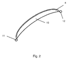
- FIG. 2 shows with a plan view of the blade of the FIG. 1 , wherein only the blade is shown in dashed lines, the arrangement of the mask 10 from above.
- the mask 10 in its dimensions and the shape in a plane transverse to the radial direction of the blade 1 corresponds to the design of the blade tip 4 and in particular of the blade tip surface.
- the mask 10 has the same banana-shaped design as the blade tip surface of the blade tip 4.
- the dimensions of the mask 10 may also be selected to be somewhat smaller than the surface of the blade tip rather than an oversize 4, depending on how much coverage of the blade tip armor 5 with the erosion protection layer 13,14 is desired.
- the distance with which the mask 10 is arranged on the blade tip 4 can be varied, and in extreme cases also in direct contact of the mask 10 on the blade tip 4 is possible.
- FIG. 3 shows in the panels a) to e), the various stages in the manufacture of a blade with a blade tip armor on the blade tip 4 and an erosion protection coating on the blade 3.
- FIG. 2 a part of a blade 1 with the blade 3 and the blade tip 4 is shown.
- a blade tip armor 5 is applied, which consists of a nickel matrix 6 and stored therein particles 7 of cubic boron nitride.
- the blade tip armor 5 is applied, for example, by electrodeposition of the nickel matrix 6 into which the cubic boron nitride particles are embedded.
- the blade tip armor can also be done in other suitable ways.
- the mask 10 is arranged in order to be able to apply the erosion protection layer 13, 14 (see Fig. 3c) ).
- the erosion protection layer 13, 14 can be deposited by physical vapor deposition (PVD), in particular by various methods of vapor deposition or deposition of the corresponding partial layers of the multi-layer erosion protection layer by sputtering. In this case, a full-surface coating of the blade 1 takes place both on the blade 3 and on the blade tip 4 above the blade tip armor 5. However, the deposition of erosion control layer in the blade tip 4 is reduced by the mask 10, so that a thinner erosion protection layer 14 in comparison to the thicker erosion protection layer 13 in the area of the airfoil 3 results (see FIG. 3 d) ).
- PVD physical vapor deposition
- the thickness of the erosion protection layer 14 in the area of the blade tip 4 is so small that the hard material particles embedded in the peak armor protrude from the erosion protection layer 14 in the form of the boron nitride particles 7.
- the thin erosion protection layer 14 in the area of the blade tip 4 or of the blade tip armor 5 is so thin that it does not impair the cutting action of the urea particles or BN particles 7.
- the mask 10 with the supports 11, 12 holding it is removed, so that there is a blade 1 with a thicker erosion protection layer 13 in the area of the blade and a thinner erosion protection layer 14 in the area of the blade tip or the blade tip armor 5 , wherein the relative indications are thicker or thinner respectively on the other part of the erosion control layer 13,14.
- the blade tip armor 5 is embedded in and surrounded by the adjacent erosion control layer 10 without overly covering the abrasive surface of the blade tip armor 5 which comes into contact with an opposing sealing material.
Applications Claiming Priority (1)
| Application Number | Priority Date | Filing Date | Title |
|---|---|---|---|
| DE102015208783.2A DE102015208783A1 (de) | 2015-05-12 | 2015-05-12 | Abdeckverfahren zur Herstellung einer Kombination von Schaufelspitzenpanzerung und Erosionsschutzschicht |
Publications (3)
| Publication Number | Publication Date |
|---|---|
| EP3093372A2 true EP3093372A2 (fr) | 2016-11-16 |
| EP3093372A3 EP3093372A3 (fr) | 2017-01-11 |
| EP3093372B1 EP3093372B1 (fr) | 2020-04-29 |
Family
ID=55854682
Family Applications (1)
| Application Number | Title | Priority Date | Filing Date |
|---|---|---|---|
| EP16167274.6A Active EP3093372B1 (fr) | 2015-05-12 | 2016-04-27 | Procede de recouvrement destine a produire une combinaison de blindage d'extremite d'aubes et couche de protection contre l'erosion |
Country Status (3)
| Country | Link |
|---|---|
| US (1) | US10415400B2 (fr) |
| EP (1) | EP3093372B1 (fr) |
| DE (1) | DE102015208783A1 (fr) |
Families Citing this family (6)
| Publication number | Priority date | Publication date | Assignee | Title |
|---|---|---|---|---|
| US11795295B2 (en) * | 2017-11-06 | 2023-10-24 | Rtx Corporation | Wear resistant coating, method of manufacture thereof and articles comprising the same |
| US20190194799A1 (en) | 2017-12-22 | 2019-06-27 | United Technologies Corporation | Line-of-sight coating fixture and apparatus |
| RU2718877C2 (ru) * | 2018-02-26 | 2020-04-15 | Федеральное государственное бюджетное образовательное учреждение высшего образования "Ухтинский государственный технический университет" | Способ нанесения функционально-ориентированного износостойкого покрытия на лопатку газотурбинного двигателя |
| US11299993B2 (en) * | 2019-10-28 | 2022-04-12 | Honeywell International Inc. | Rotor assembly for in-machine grinding of shroud member and methods of using the same |
| US11286794B2 (en) * | 2019-12-17 | 2022-03-29 | Rolls-Royce North American Technologies, Inc. | Erosion-resistant coating with patterned leading edge |
| DE102020206202A1 (de) | 2020-05-18 | 2021-11-18 | MTU Aero Engines AG | Schaufel für eine Strömungsmaschine mit Schaufelspitzenpanzerung und Erosionsschutzschicht und Verfahren zur Herstellung Derselben |
Citations (1)
| Publication number | Priority date | Publication date | Assignee | Title |
|---|---|---|---|---|
| DE102010049398A1 (de) | 2009-11-02 | 2011-05-05 | Alstom Technology Ltd. | Verschleiss- und oxidationsbeständige Turbinenschaufel |
Family Cites Families (22)
| Publication number | Priority date | Publication date | Assignee | Title |
|---|---|---|---|---|
| US4610698A (en) * | 1984-06-25 | 1986-09-09 | United Technologies Corporation | Abrasive surface coating process for superalloys |
| US4863538A (en) * | 1986-10-17 | 1989-09-05 | Board Of Regents, The University Of Texas System | Method and apparatus for producing parts by selective sintering |
| US5603603A (en) * | 1993-12-08 | 1997-02-18 | United Technologies Corporation | Abrasive blade tip |
| US5565035A (en) * | 1996-03-14 | 1996-10-15 | United Technologies Corporation | Fixture for masking a portion of an airfoil during application of a coating |
| US5704759A (en) * | 1996-10-21 | 1998-01-06 | Alliedsignal Inc. | Abrasive tip/abradable shroud system and method for gas turbine compressor clearance control |
| US5952110A (en) * | 1996-12-24 | 1999-09-14 | General Electric Company | Abrasive ceramic matrix turbine blade tip and method for forming |
| US5803971A (en) * | 1997-01-13 | 1998-09-08 | United Technologies Corporation | Modular coating fixture |
| US6224337B1 (en) * | 1999-09-17 | 2001-05-01 | General Electric Company | Thermal barrier coated squealer tip cavity |
| US6434876B1 (en) * | 2000-09-26 | 2002-08-20 | General Electric Company | Method of applying a particle-embedded coating to a substrate |
| JP2003148103A (ja) * | 2001-11-09 | 2003-05-21 | Mitsubishi Heavy Ind Ltd | タービンおよびその製造方法 |
| EP1352988A1 (fr) * | 2002-04-10 | 2003-10-15 | Siemens Aktiengesellschaft | Procédé de revêtement d'un objet |
| US7473072B2 (en) * | 2005-02-01 | 2009-01-06 | Honeywell International Inc. | Turbine blade tip and shroud clearance control coating system |
| US7510370B2 (en) * | 2005-02-01 | 2009-03-31 | Honeywell International Inc. | Turbine blade tip and shroud clearance control coating system |
| DE102005060712A1 (de) * | 2005-12-20 | 2007-06-21 | Mtu Aero Engines Gmbh | Verfahren zum Herstellen einer Schaufelspitzenpanzerung |
| US7980820B2 (en) * | 2007-08-27 | 2011-07-19 | United Technologies Corporation | Turbine engine blade cooling |
| EP2317078B2 (fr) * | 2009-11-02 | 2021-09-01 | Ansaldo Energia IP UK Limited | Aube de turbine abrasive monocristalline |
| US20110116912A1 (en) * | 2009-11-13 | 2011-05-19 | Mccall Thomas | Zoned discontinuous coating for high pressure turbine component |
| US9145775B2 (en) * | 2012-03-02 | 2015-09-29 | United Technologies Corporation | Tapered thermal coating for airfoil |
| US20150368786A1 (en) * | 2013-02-12 | 2015-12-24 | United Technologies Corporation | Metallic coating fixed stator tip treatment |
| US10151245B2 (en) * | 2013-03-06 | 2018-12-11 | United Technologies Corporation | Fixturing for thermal spray coating of gas turbine components |
| DE102013224568A1 (de) * | 2013-11-29 | 2015-06-03 | Siemens Aktiengesellschaft | Verfahren zur Erzeugung einer Fase, Bauteil mit Fase und Vorrichtung |
| DE102013224566A1 (de) * | 2013-11-29 | 2015-06-03 | Siemens Aktiengesellschaft | Vorrichtung zur Maskierung auf Wolframlegierungsbasis und eine Wolframlegierung |
-
2015
- 2015-05-12 DE DE102015208783.2A patent/DE102015208783A1/de not_active Ceased
-
2016
- 2016-04-27 EP EP16167274.6A patent/EP3093372B1/fr active Active
- 2016-05-12 US US15/152,671 patent/US10415400B2/en active Active
Patent Citations (1)
| Publication number | Priority date | Publication date | Assignee | Title |
|---|---|---|---|---|
| DE102010049398A1 (de) | 2009-11-02 | 2011-05-05 | Alstom Technology Ltd. | Verschleiss- und oxidationsbeständige Turbinenschaufel |
Also Published As
| Publication number | Publication date |
|---|---|
| DE102015208783A1 (de) | 2016-11-17 |
| EP3093372A3 (fr) | 2017-01-11 |
| US20160333706A1 (en) | 2016-11-17 |
| US20190301291A9 (en) | 2019-10-03 |
| EP3093372B1 (fr) | 2020-04-29 |
| US10415400B2 (en) | 2019-09-17 |
Similar Documents
| Publication | Publication Date | Title |
|---|---|---|
| EP3093372B1 (fr) | Procede de recouvrement destine a produire une combinaison de blindage d'extremite d'aubes et couche de protection contre l'erosion | |
| EP1741876B1 (fr) | Aube de turbomachine comprenant une extrémité blindée | |
| DE102010049398A1 (de) | Verschleiss- und oxidationsbeständige Turbinenschaufel | |
| EP3191244A1 (fr) | Procédé de fabrication d'une aube mobile et aube ainsi obtenue | |
| EP1819905A1 (fr) | Système de couches, utilisation et procédé pour la fabrication d'un système multicouche | |
| EP3467261B1 (fr) | Procédé de fabrication d'un élément d'aube en tandem | |
| DE102015201782A1 (de) | Leitschaufelring für eine Strömungsmaschine | |
| EP3093371B1 (fr) | Combinaison de blindage d'extremite d'aubes et de couche de protection contre l'erosion et son procede de fabrication | |
| DE102009033618A1 (de) | Verfahren zur Frequenzverstimmung eines Rotorkörpers einer Gasturbine und ein Rotor einer Gasturbine | |
| WO2007033650A1 (fr) | Procede de production d'une couche de protection, couche de protection et composant pourvu d'une couche de protection | |
| EP2984294B1 (fr) | Aube de turbine avec arête de plate-forme étagée et biseauté | |
| EP3246430B1 (fr) | Procédé de fabrication d'aubes ou de système d'aubes d'une turbomachine comprenant des couches de protection contre l'érosion et composant ainsi fabriqué | |
| EP3153269B1 (fr) | Réparation de surfaces d'objets usées | |
| EP3628030B1 (fr) | Méthode de maintenance d'une turbomachine | |
| EP2004361B1 (fr) | Procédé de réparation d'un segment d'aubes directrices | |
| EP3156588B1 (fr) | Procede de reparation d'elements d'etancheite | |
| DE102017204243A1 (de) | Dichtfin mit zumindest einer gewölbten Seitenflanke | |
| EP3312388B1 (fr) | Pièce de rotor, compresseur, turbine et procédé de fabrication associés | |
| DE102016211337A1 (de) | Verdickter radial äußerer Ringbereich eines Dichtfins | |
| WO2021233496A1 (fr) | Aube pour une turbomachine, ayant un blindage de pointe d'aube et une couche anti-érosion, et procédé de production de ladite aube | |
| EP2454451B1 (fr) | Rotor avec éléments d'accouplement pour accoupler mécaniquement des aubes | |
| EP1508399B1 (fr) | Aube de turbomachine et procédé pour empêcher la propagation des fissures dans une aube de turbomachine | |
| DE102018200964A1 (de) | Rotorschaufeldeckband für eine Strömungsmaschine, Rotorschaufel, Verfahren zum Herstellen eines Rotorschaufeldeckbands und einer Rotorschaufel | |
| WO2018024759A1 (fr) | Procédé de fabrication d'une structure de conduit et constituants | |
| EP2518268A1 (fr) | Composant de turbine avec masse d'équilibrage revêtue pour l'utilisation à des températures élevées |
Legal Events
| Date | Code | Title | Description |
|---|---|---|---|
| PUAI | Public reference made under article 153(3) epc to a published international application that has entered the european phase |
Free format text: ORIGINAL CODE: 0009012 |
|
| AK | Designated contracting states |
Kind code of ref document: A2 Designated state(s): AL AT BE BG CH CY CZ DE DK EE ES FI FR GB GR HR HU IE IS IT LI LT LU LV MC MK MT NL NO PL PT RO RS SE SI SK SM TR |
|
| AX | Request for extension of the european patent |
Extension state: BA ME |
|
| PUAL | Search report despatched |
Free format text: ORIGINAL CODE: 0009013 |
|
| AK | Designated contracting states |
Kind code of ref document: A3 Designated state(s): AL AT BE BG CH CY CZ DE DK EE ES FI FR GB GR HR HU IE IS IT LI LT LU LV MC MK MT NL NO PL PT RO RS SE SI SK SM TR |
|
| AX | Request for extension of the european patent |
Extension state: BA ME |
|
| RIC1 | Information provided on ipc code assigned before grant |
Ipc: C23C 28/00 20060101AFI20161207BHEP Ipc: F01D 5/28 20060101ALI20161207BHEP Ipc: C23C 14/04 20060101ALI20161207BHEP |
|
| STAA | Information on the status of an ep patent application or granted ep patent |
Free format text: STATUS: REQUEST FOR EXAMINATION WAS MADE |
|
| 17P | Request for examination filed |
Effective date: 20170711 |
|
| RBV | Designated contracting states (corrected) |
Designated state(s): AL AT BE BG CH CY CZ DE DK EE ES FI FR GB GR HR HU IE IS IT LI LT LU LV MC MK MT NL NO PL PT RO RS SE SI SK SM TR |
|
| STAA | Information on the status of an ep patent application or granted ep patent |
Free format text: STATUS: EXAMINATION IS IN PROGRESS |
|
| 17Q | First examination report despatched |
Effective date: 20180411 |
|
| GRAP | Despatch of communication of intention to grant a patent |
Free format text: ORIGINAL CODE: EPIDOSNIGR1 |
|
| STAA | Information on the status of an ep patent application or granted ep patent |
Free format text: STATUS: GRANT OF PATENT IS INTENDED |
|
| RIC1 | Information provided on ipc code assigned before grant |
Ipc: C23C 14/04 20060101ALI20191118BHEP Ipc: F01D 5/28 20060101ALI20191118BHEP Ipc: C23C 28/00 20060101AFI20191118BHEP Ipc: F01D 11/12 20060101ALI20191118BHEP |
|
| INTG | Intention to grant announced |
Effective date: 20191209 |
|
| GRAS | Grant fee paid |
Free format text: ORIGINAL CODE: EPIDOSNIGR3 |
|
| GRAA | (expected) grant |
Free format text: ORIGINAL CODE: 0009210 |
|
| STAA | Information on the status of an ep patent application or granted ep patent |
Free format text: STATUS: THE PATENT HAS BEEN GRANTED |
|
| AK | Designated contracting states |
Kind code of ref document: B1 Designated state(s): AL AT BE BG CH CY CZ DE DK EE ES FI FR GB GR HR HU IE IS IT LI LT LU LV MC MK MT NL NO PL PT RO RS SE SI SK SM TR |
|
| REG | Reference to a national code |
Ref country code: GB Ref legal event code: FG4D Free format text: NOT ENGLISH |
|
| REG | Reference to a national code |
Ref country code: CH Ref legal event code: EP |
|
| REG | Reference to a national code |
Ref country code: AT Ref legal event code: REF Ref document number: 1263407 Country of ref document: AT Kind code of ref document: T Effective date: 20200515 |
|
| REG | Reference to a national code |
Ref country code: DE Ref legal event code: R096 Ref document number: 502016009721 Country of ref document: DE |
|
| REG | Reference to a national code |
Ref country code: IE Ref legal event code: FG4D Free format text: LANGUAGE OF EP DOCUMENT: GERMAN |
|
| REG | Reference to a national code |
Ref country code: NL Ref legal event code: MP Effective date: 20200429 |
|
| REG | Reference to a national code |
Ref country code: LT Ref legal event code: MG4D |
|
| PG25 | Lapsed in a contracting state [announced via postgrant information from national office to epo] |
Ref country code: NO Free format text: LAPSE BECAUSE OF FAILURE TO SUBMIT A TRANSLATION OF THE DESCRIPTION OR TO PAY THE FEE WITHIN THE PRESCRIBED TIME-LIMIT Effective date: 20200729 Ref country code: IS Free format text: LAPSE BECAUSE OF FAILURE TO SUBMIT A TRANSLATION OF THE DESCRIPTION OR TO PAY THE FEE WITHIN THE PRESCRIBED TIME-LIMIT Effective date: 20200829 Ref country code: PT Free format text: LAPSE BECAUSE OF FAILURE TO SUBMIT A TRANSLATION OF THE DESCRIPTION OR TO PAY THE FEE WITHIN THE PRESCRIBED TIME-LIMIT Effective date: 20200831 Ref country code: FI Free format text: LAPSE BECAUSE OF FAILURE TO SUBMIT A TRANSLATION OF THE DESCRIPTION OR TO PAY THE FEE WITHIN THE PRESCRIBED TIME-LIMIT Effective date: 20200429 Ref country code: SE Free format text: LAPSE BECAUSE OF FAILURE TO SUBMIT A TRANSLATION OF THE DESCRIPTION OR TO PAY THE FEE WITHIN THE PRESCRIBED TIME-LIMIT Effective date: 20200429 Ref country code: GR Free format text: LAPSE BECAUSE OF FAILURE TO SUBMIT A TRANSLATION OF THE DESCRIPTION OR TO PAY THE FEE WITHIN THE PRESCRIBED TIME-LIMIT Effective date: 20200730 Ref country code: LT Free format text: LAPSE BECAUSE OF FAILURE TO SUBMIT A TRANSLATION OF THE DESCRIPTION OR TO PAY THE FEE WITHIN THE PRESCRIBED TIME-LIMIT Effective date: 20200429 |
|
| PG25 | Lapsed in a contracting state [announced via postgrant information from national office to epo] |
Ref country code: HR Free format text: LAPSE BECAUSE OF FAILURE TO SUBMIT A TRANSLATION OF THE DESCRIPTION OR TO PAY THE FEE WITHIN THE PRESCRIBED TIME-LIMIT Effective date: 20200429 Ref country code: BG Free format text: LAPSE BECAUSE OF FAILURE TO SUBMIT A TRANSLATION OF THE DESCRIPTION OR TO PAY THE FEE WITHIN THE PRESCRIBED TIME-LIMIT Effective date: 20200729 Ref country code: RS Free format text: LAPSE BECAUSE OF FAILURE TO SUBMIT A TRANSLATION OF THE DESCRIPTION OR TO PAY THE FEE WITHIN THE PRESCRIBED TIME-LIMIT Effective date: 20200429 Ref country code: LV Free format text: LAPSE BECAUSE OF FAILURE TO SUBMIT A TRANSLATION OF THE DESCRIPTION OR TO PAY THE FEE WITHIN THE PRESCRIBED TIME-LIMIT Effective date: 20200429 |
|
| PG25 | Lapsed in a contracting state [announced via postgrant information from national office to epo] |
Ref country code: NL Free format text: LAPSE BECAUSE OF FAILURE TO SUBMIT A TRANSLATION OF THE DESCRIPTION OR TO PAY THE FEE WITHIN THE PRESCRIBED TIME-LIMIT Effective date: 20200429 Ref country code: AL Free format text: LAPSE BECAUSE OF FAILURE TO SUBMIT A TRANSLATION OF THE DESCRIPTION OR TO PAY THE FEE WITHIN THE PRESCRIBED TIME-LIMIT Effective date: 20200429 |
|
| PG25 | Lapsed in a contracting state [announced via postgrant information from national office to epo] |
Ref country code: ES Free format text: LAPSE BECAUSE OF FAILURE TO SUBMIT A TRANSLATION OF THE DESCRIPTION OR TO PAY THE FEE WITHIN THE PRESCRIBED TIME-LIMIT Effective date: 20200429 Ref country code: SM Free format text: LAPSE BECAUSE OF FAILURE TO SUBMIT A TRANSLATION OF THE DESCRIPTION OR TO PAY THE FEE WITHIN THE PRESCRIBED TIME-LIMIT Effective date: 20200429 Ref country code: EE Free format text: LAPSE BECAUSE OF FAILURE TO SUBMIT A TRANSLATION OF THE DESCRIPTION OR TO PAY THE FEE WITHIN THE PRESCRIBED TIME-LIMIT Effective date: 20200429 Ref country code: IT Free format text: LAPSE BECAUSE OF FAILURE TO SUBMIT A TRANSLATION OF THE DESCRIPTION OR TO PAY THE FEE WITHIN THE PRESCRIBED TIME-LIMIT Effective date: 20200429 Ref country code: DK Free format text: LAPSE BECAUSE OF FAILURE TO SUBMIT A TRANSLATION OF THE DESCRIPTION OR TO PAY THE FEE WITHIN THE PRESCRIBED TIME-LIMIT Effective date: 20200429 Ref country code: RO Free format text: LAPSE BECAUSE OF FAILURE TO SUBMIT A TRANSLATION OF THE DESCRIPTION OR TO PAY THE FEE WITHIN THE PRESCRIBED TIME-LIMIT Effective date: 20200429 Ref country code: CZ Free format text: LAPSE BECAUSE OF FAILURE TO SUBMIT A TRANSLATION OF THE DESCRIPTION OR TO PAY THE FEE WITHIN THE PRESCRIBED TIME-LIMIT Effective date: 20200429 |
|
| REG | Reference to a national code |
Ref country code: DE Ref legal event code: R097 Ref document number: 502016009721 Country of ref document: DE |
|
| PG25 | Lapsed in a contracting state [announced via postgrant information from national office to epo] |
Ref country code: PL Free format text: LAPSE BECAUSE OF FAILURE TO SUBMIT A TRANSLATION OF THE DESCRIPTION OR TO PAY THE FEE WITHIN THE PRESCRIBED TIME-LIMIT Effective date: 20200429 Ref country code: SK Free format text: LAPSE BECAUSE OF FAILURE TO SUBMIT A TRANSLATION OF THE DESCRIPTION OR TO PAY THE FEE WITHIN THE PRESCRIBED TIME-LIMIT Effective date: 20200429 |
|
| PLBE | No opposition filed within time limit |
Free format text: ORIGINAL CODE: 0009261 |
|
| STAA | Information on the status of an ep patent application or granted ep patent |
Free format text: STATUS: NO OPPOSITION FILED WITHIN TIME LIMIT |
|
| 26N | No opposition filed |
Effective date: 20210201 |
|
| PG25 | Lapsed in a contracting state [announced via postgrant information from national office to epo] |
Ref country code: SI Free format text: LAPSE BECAUSE OF FAILURE TO SUBMIT A TRANSLATION OF THE DESCRIPTION OR TO PAY THE FEE WITHIN THE PRESCRIBED TIME-LIMIT Effective date: 20200429 |
|
| PG25 | Lapsed in a contracting state [announced via postgrant information from national office to epo] |
Ref country code: MC Free format text: LAPSE BECAUSE OF FAILURE TO SUBMIT A TRANSLATION OF THE DESCRIPTION OR TO PAY THE FEE WITHIN THE PRESCRIBED TIME-LIMIT Effective date: 20200429 |
|
| PG25 | Lapsed in a contracting state [announced via postgrant information from national office to epo] |
Ref country code: LU Free format text: LAPSE BECAUSE OF NON-PAYMENT OF DUE FEES Effective date: 20210427 |
|
| REG | Reference to a national code |
Ref country code: BE Ref legal event code: MM Effective date: 20210430 |
|
| PG25 | Lapsed in a contracting state [announced via postgrant information from national office to epo] |
Ref country code: LI Free format text: LAPSE BECAUSE OF NON-PAYMENT OF DUE FEES Effective date: 20210430 Ref country code: CH Free format text: LAPSE BECAUSE OF NON-PAYMENT OF DUE FEES Effective date: 20210430 |
|
| PG25 | Lapsed in a contracting state [announced via postgrant information from national office to epo] |
Ref country code: IE Free format text: LAPSE BECAUSE OF NON-PAYMENT OF DUE FEES Effective date: 20210427 |
|
| REG | Reference to a national code |
Ref country code: AT Ref legal event code: MM01 Ref document number: 1263407 Country of ref document: AT Kind code of ref document: T Effective date: 20210427 |
|
| PG25 | Lapsed in a contracting state [announced via postgrant information from national office to epo] |
Ref country code: BE Free format text: LAPSE BECAUSE OF NON-PAYMENT OF DUE FEES Effective date: 20210430 |
|
| PG25 | Lapsed in a contracting state [announced via postgrant information from national office to epo] |
Ref country code: AT Free format text: LAPSE BECAUSE OF NON-PAYMENT OF DUE FEES Effective date: 20210427 |
|
| PG25 | Lapsed in a contracting state [announced via postgrant information from national office to epo] |
Ref country code: HU Free format text: LAPSE BECAUSE OF FAILURE TO SUBMIT A TRANSLATION OF THE DESCRIPTION OR TO PAY THE FEE WITHIN THE PRESCRIBED TIME-LIMIT; INVALID AB INITIO Effective date: 20160427 |
|
| PG25 | Lapsed in a contracting state [announced via postgrant information from national office to epo] |
Ref country code: CY Free format text: LAPSE BECAUSE OF FAILURE TO SUBMIT A TRANSLATION OF THE DESCRIPTION OR TO PAY THE FEE WITHIN THE PRESCRIBED TIME-LIMIT Effective date: 20200429 |
|
| PGFP | Annual fee paid to national office [announced via postgrant information from national office to epo] |
Ref country code: FR Payment date: 20230417 Year of fee payment: 8 Ref country code: DE Payment date: 20230418 Year of fee payment: 8 |
|
| PGFP | Annual fee paid to national office [announced via postgrant information from national office to epo] |
Ref country code: GB Payment date: 20230420 Year of fee payment: 8 |