US10151245B2 - Fixturing for thermal spray coating of gas turbine components - Google Patents
Fixturing for thermal spray coating of gas turbine components Download PDFInfo
- Publication number
- US10151245B2 US10151245B2 US14/772,180 US201414772180A US10151245B2 US 10151245 B2 US10151245 B2 US 10151245B2 US 201414772180 A US201414772180 A US 201414772180A US 10151245 B2 US10151245 B2 US 10151245B2
- Authority
- US
- United States
- Prior art keywords
- workpiece
- support
- backplate
- recited
- standoff
- Prior art date
- Legal status (The legal status is an assumption and is not a legal conclusion. Google has not performed a legal analysis and makes no representation as to the accuracy of the status listed.)
- Active, expires
Links
Images


Classifications
-
- F—MECHANICAL ENGINEERING; LIGHTING; HEATING; WEAPONS; BLASTING
- F02—COMBUSTION ENGINES; HOT-GAS OR COMBUSTION-PRODUCT ENGINE PLANTS
- F02C—GAS-TURBINE PLANTS; AIR INTAKES FOR JET-PROPULSION PLANTS; CONTROLLING FUEL SUPPLY IN AIR-BREATHING JET-PROPULSION PLANTS
- F02C7/00—Features, components parts, details or accessories, not provided for in, or of interest apart form groups F02C1/00 - F02C6/00; Air intakes for jet-propulsion plants
- F02C7/20—Mounting or supporting of plant; Accommodating heat expansion or creep
-
- B—PERFORMING OPERATIONS; TRANSPORTING
- B05—SPRAYING OR ATOMISING IN GENERAL; APPLYING FLUENT MATERIALS TO SURFACES, IN GENERAL
- B05B—SPRAYING APPARATUS; ATOMISING APPARATUS; NOZZLES
- B05B12/00—Arrangements for controlling delivery; Arrangements for controlling the spray area
- B05B12/16—Arrangements for controlling delivery; Arrangements for controlling the spray area for controlling the spray area
- B05B12/20—Masking elements, i.e. elements defining uncoated areas on an object to be coated
-
- B—PERFORMING OPERATIONS; TRANSPORTING
- B05—SPRAYING OR ATOMISING IN GENERAL; APPLYING FLUENT MATERIALS TO SURFACES, IN GENERAL
- B05C—APPARATUS FOR APPLYING FLUENT MATERIALS TO SURFACES, IN GENERAL
- B05C21/00—Accessories or implements for use in connection with applying liquids or other fluent materials to surfaces, not provided for in groups B05C1/00 - B05C19/00
- B05C21/005—Masking devices
-
- C—CHEMISTRY; METALLURGY
- C23—COATING METALLIC MATERIAL; COATING MATERIAL WITH METALLIC MATERIAL; CHEMICAL SURFACE TREATMENT; DIFFUSION TREATMENT OF METALLIC MATERIAL; COATING BY VACUUM EVAPORATION, BY SPUTTERING, BY ION IMPLANTATION OR BY CHEMICAL VAPOUR DEPOSITION, IN GENERAL; INHIBITING CORROSION OF METALLIC MATERIAL OR INCRUSTATION IN GENERAL
- C23C—COATING METALLIC MATERIAL; COATING MATERIAL WITH METALLIC MATERIAL; SURFACE TREATMENT OF METALLIC MATERIAL BY DIFFUSION INTO THE SURFACE, BY CHEMICAL CONVERSION OR SUBSTITUTION; COATING BY VACUUM EVAPORATION, BY SPUTTERING, BY ION IMPLANTATION OR BY CHEMICAL VAPOUR DEPOSITION, IN GENERAL
- C23C14/00—Coating by vacuum evaporation, by sputtering or by ion implantation of the coating forming material
- C23C14/04—Coating on selected surface areas, e.g. using masks
- C23C14/042—Coating on selected surface areas, e.g. using masks using masks
-
- C—CHEMISTRY; METALLURGY
- C23—COATING METALLIC MATERIAL; COATING MATERIAL WITH METALLIC MATERIAL; CHEMICAL SURFACE TREATMENT; DIFFUSION TREATMENT OF METALLIC MATERIAL; COATING BY VACUUM EVAPORATION, BY SPUTTERING, BY ION IMPLANTATION OR BY CHEMICAL VAPOUR DEPOSITION, IN GENERAL; INHIBITING CORROSION OF METALLIC MATERIAL OR INCRUSTATION IN GENERAL
- C23C—COATING METALLIC MATERIAL; COATING MATERIAL WITH METALLIC MATERIAL; SURFACE TREATMENT OF METALLIC MATERIAL BY DIFFUSION INTO THE SURFACE, BY CHEMICAL CONVERSION OR SUBSTITUTION; COATING BY VACUUM EVAPORATION, BY SPUTTERING, BY ION IMPLANTATION OR BY CHEMICAL VAPOUR DEPOSITION, IN GENERAL
- C23C28/00—Coating for obtaining at least two superposed coatings either by methods not provided for in a single one of groups C23C2/00 - C23C26/00 or by combinations of methods provided for in subclasses C23C and C25C or C25D
- C23C28/30—Coatings combining at least one metallic layer and at least one inorganic non-metallic layer
- C23C28/32—Coatings combining at least one metallic layer and at least one inorganic non-metallic layer including at least one pure metallic layer
- C23C28/321—Coatings combining at least one metallic layer and at least one inorganic non-metallic layer including at least one pure metallic layer with at least one metal alloy layer
- C23C28/3215—Coatings combining at least one metallic layer and at least one inorganic non-metallic layer including at least one pure metallic layer with at least one metal alloy layer at least one MCrAlX layer
-
- C—CHEMISTRY; METALLURGY
- C23—COATING METALLIC MATERIAL; COATING MATERIAL WITH METALLIC MATERIAL; CHEMICAL SURFACE TREATMENT; DIFFUSION TREATMENT OF METALLIC MATERIAL; COATING BY VACUUM EVAPORATION, BY SPUTTERING, BY ION IMPLANTATION OR BY CHEMICAL VAPOUR DEPOSITION, IN GENERAL; INHIBITING CORROSION OF METALLIC MATERIAL OR INCRUSTATION IN GENERAL
- C23C—COATING METALLIC MATERIAL; COATING MATERIAL WITH METALLIC MATERIAL; SURFACE TREATMENT OF METALLIC MATERIAL BY DIFFUSION INTO THE SURFACE, BY CHEMICAL CONVERSION OR SUBSTITUTION; COATING BY VACUUM EVAPORATION, BY SPUTTERING, BY ION IMPLANTATION OR BY CHEMICAL VAPOUR DEPOSITION, IN GENERAL
- C23C28/00—Coating for obtaining at least two superposed coatings either by methods not provided for in a single one of groups C23C2/00 - C23C26/00 or by combinations of methods provided for in subclasses C23C and C25C or C25D
- C23C28/30—Coatings combining at least one metallic layer and at least one inorganic non-metallic layer
- C23C28/34—Coatings combining at least one metallic layer and at least one inorganic non-metallic layer including at least one inorganic non-metallic material layer, e.g. metal carbide, nitride, boride, silicide layer and their mixtures, enamels, phosphates and sulphates
- C23C28/345—Coatings combining at least one metallic layer and at least one inorganic non-metallic layer including at least one inorganic non-metallic material layer, e.g. metal carbide, nitride, boride, silicide layer and their mixtures, enamels, phosphates and sulphates with at least one oxide layer
- C23C28/3455—Coatings combining at least one metallic layer and at least one inorganic non-metallic layer including at least one inorganic non-metallic material layer, e.g. metal carbide, nitride, boride, silicide layer and their mixtures, enamels, phosphates and sulphates with at least one oxide layer with a refractory ceramic layer, e.g. refractory metal oxide, ZrO2, rare earth oxides or a thermal barrier system comprising at least one refractory oxide layer
-
- C—CHEMISTRY; METALLURGY
- C23—COATING METALLIC MATERIAL; COATING MATERIAL WITH METALLIC MATERIAL; CHEMICAL SURFACE TREATMENT; DIFFUSION TREATMENT OF METALLIC MATERIAL; COATING BY VACUUM EVAPORATION, BY SPUTTERING, BY ION IMPLANTATION OR BY CHEMICAL VAPOUR DEPOSITION, IN GENERAL; INHIBITING CORROSION OF METALLIC MATERIAL OR INCRUSTATION IN GENERAL
- C23C—COATING METALLIC MATERIAL; COATING MATERIAL WITH METALLIC MATERIAL; SURFACE TREATMENT OF METALLIC MATERIAL BY DIFFUSION INTO THE SURFACE, BY CHEMICAL CONVERSION OR SUBSTITUTION; COATING BY VACUUM EVAPORATION, BY SPUTTERING, BY ION IMPLANTATION OR BY CHEMICAL VAPOUR DEPOSITION, IN GENERAL
- C23C4/00—Coating by spraying the coating material in the molten state, e.g. by flame, plasma or electric discharge
- C23C4/01—Selective coating, e.g. pattern coating, without pre-treatment of the material to be coated
-
- C—CHEMISTRY; METALLURGY
- C23—COATING METALLIC MATERIAL; COATING MATERIAL WITH METALLIC MATERIAL; CHEMICAL SURFACE TREATMENT; DIFFUSION TREATMENT OF METALLIC MATERIAL; COATING BY VACUUM EVAPORATION, BY SPUTTERING, BY ION IMPLANTATION OR BY CHEMICAL VAPOUR DEPOSITION, IN GENERAL; INHIBITING CORROSION OF METALLIC MATERIAL OR INCRUSTATION IN GENERAL
- C23C—COATING METALLIC MATERIAL; COATING MATERIAL WITH METALLIC MATERIAL; SURFACE TREATMENT OF METALLIC MATERIAL BY DIFFUSION INTO THE SURFACE, BY CHEMICAL CONVERSION OR SUBSTITUTION; COATING BY VACUUM EVAPORATION, BY SPUTTERING, BY ION IMPLANTATION OR BY CHEMICAL VAPOUR DEPOSITION, IN GENERAL
- C23C4/00—Coating by spraying the coating material in the molten state, e.g. by flame, plasma or electric discharge
- C23C4/02—Pretreatment of the material to be coated, e.g. for coating on selected surface areas
-
- C—CHEMISTRY; METALLURGY
- C23—COATING METALLIC MATERIAL; COATING MATERIAL WITH METALLIC MATERIAL; CHEMICAL SURFACE TREATMENT; DIFFUSION TREATMENT OF METALLIC MATERIAL; COATING BY VACUUM EVAPORATION, BY SPUTTERING, BY ION IMPLANTATION OR BY CHEMICAL VAPOUR DEPOSITION, IN GENERAL; INHIBITING CORROSION OF METALLIC MATERIAL OR INCRUSTATION IN GENERAL
- C23C—COATING METALLIC MATERIAL; COATING MATERIAL WITH METALLIC MATERIAL; SURFACE TREATMENT OF METALLIC MATERIAL BY DIFFUSION INTO THE SURFACE, BY CHEMICAL CONVERSION OR SUBSTITUTION; COATING BY VACUUM EVAPORATION, BY SPUTTERING, BY ION IMPLANTATION OR BY CHEMICAL VAPOUR DEPOSITION, IN GENERAL
- C23C4/00—Coating by spraying the coating material in the molten state, e.g. by flame, plasma or electric discharge
- C23C4/04—Coating by spraying the coating material in the molten state, e.g. by flame, plasma or electric discharge characterised by the coating material
- C23C4/10—Oxides, borides, carbides, nitrides or silicides; Mixtures thereof
- C23C4/11—Oxides
-
- F—MECHANICAL ENGINEERING; LIGHTING; HEATING; WEAPONS; BLASTING
- F01—MACHINES OR ENGINES IN GENERAL; ENGINE PLANTS IN GENERAL; STEAM ENGINES
- F01D—NON-POSITIVE DISPLACEMENT MACHINES OR ENGINES, e.g. STEAM TURBINES
- F01D25/00—Component parts, details, or accessories, not provided for in, or of interest apart from, other groups
- F01D25/28—Supporting or mounting arrangements, e.g. for turbine casing
- F01D25/285—Temporary support structures, e.g. for testing, assembling, installing, repairing; Assembly methods using such structures
-
- B—PERFORMING OPERATIONS; TRANSPORTING
- B05—SPRAYING OR ATOMISING IN GENERAL; APPLYING FLUENT MATERIALS TO SURFACES, IN GENERAL
- B05B—SPRAYING APPARATUS; ATOMISING APPARATUS; NOZZLES
- B05B13/00—Machines or plants for applying liquids or other fluent materials to surfaces of objects or other work by spraying, not covered by groups B05B1/00 - B05B11/00
- B05B13/02—Means for supporting work; Arrangement or mounting of spray heads; Adaptation or arrangement of means for feeding work
- B05B13/0285—Stands for supporting individual articles to be sprayed, e.g. doors, vehicle body parts
-
- B—PERFORMING OPERATIONS; TRANSPORTING
- B05—SPRAYING OR ATOMISING IN GENERAL; APPLYING FLUENT MATERIALS TO SURFACES, IN GENERAL
- B05C—APPARATUS FOR APPLYING FLUENT MATERIALS TO SURFACES, IN GENERAL
- B05C13/00—Means for manipulating or holding work, e.g. for separate articles
- B05C13/02—Means for manipulating or holding work, e.g. for separate articles for particular articles
-
- F—MECHANICAL ENGINEERING; LIGHTING; HEATING; WEAPONS; BLASTING
- F05—INDEXING SCHEMES RELATING TO ENGINES OR PUMPS IN VARIOUS SUBCLASSES OF CLASSES F01-F04
- F05D—INDEXING SCHEME FOR ASPECTS RELATING TO NON-POSITIVE-DISPLACEMENT MACHINES OR ENGINES, GAS-TURBINES OR JET-PROPULSION PLANTS
- F05D2230/00—Manufacture
- F05D2230/30—Manufacture with deposition of material
- F05D2230/31—Layer deposition
- F05D2230/311—Layer deposition by torch or flame spraying
-
- F—MECHANICAL ENGINEERING; LIGHTING; HEATING; WEAPONS; BLASTING
- F05—INDEXING SCHEMES RELATING TO ENGINES OR PUMPS IN VARIOUS SUBCLASSES OF CLASSES F01-F04
- F05D—INDEXING SCHEME FOR ASPECTS RELATING TO NON-POSITIVE-DISPLACEMENT MACHINES OR ENGINES, GAS-TURBINES OR JET-PROPULSION PLANTS
- F05D2230/00—Manufacture
- F05D2230/30—Manufacture with deposition of material
- F05D2230/31—Layer deposition
- F05D2230/312—Layer deposition by plasma spraying
-
- F—MECHANICAL ENGINEERING; LIGHTING; HEATING; WEAPONS; BLASTING
- F05—INDEXING SCHEMES RELATING TO ENGINES OR PUMPS IN VARIOUS SUBCLASSES OF CLASSES F01-F04
- F05D—INDEXING SCHEME FOR ASPECTS RELATING TO NON-POSITIVE-DISPLACEMENT MACHINES OR ENGINES, GAS-TURBINES OR JET-PROPULSION PLANTS
- F05D2230/00—Manufacture
- F05D2230/90—Coating; Surface treatment
-
- F—MECHANICAL ENGINEERING; LIGHTING; HEATING; WEAPONS; BLASTING
- F05—INDEXING SCHEMES RELATING TO ENGINES OR PUMPS IN VARIOUS SUBCLASSES OF CLASSES F01-F04
- F05D—INDEXING SCHEME FOR ASPECTS RELATING TO NON-POSITIVE-DISPLACEMENT MACHINES OR ENGINES, GAS-TURBINES OR JET-PROPULSION PLANTS
- F05D2240/00—Components
- F05D2240/35—Combustors or associated equipment
-
- F—MECHANICAL ENGINEERING; LIGHTING; HEATING; WEAPONS; BLASTING
- F05—INDEXING SCHEMES RELATING TO ENGINES OR PUMPS IN VARIOUS SUBCLASSES OF CLASSES F01-F04
- F05D—INDEXING SCHEME FOR ASPECTS RELATING TO NON-POSITIVE-DISPLACEMENT MACHINES OR ENGINES, GAS-TURBINES OR JET-PROPULSION PLANTS
- F05D2240/00—Components
- F05D2240/90—Mounting on supporting structures or systems
-
- Y—GENERAL TAGGING OF NEW TECHNOLOGICAL DEVELOPMENTS; GENERAL TAGGING OF CROSS-SECTIONAL TECHNOLOGIES SPANNING OVER SEVERAL SECTIONS OF THE IPC; TECHNICAL SUBJECTS COVERED BY FORMER USPC CROSS-REFERENCE ART COLLECTIONS [XRACs] AND DIGESTS
- Y02—TECHNOLOGIES OR APPLICATIONS FOR MITIGATION OR ADAPTATION AGAINST CLIMATE CHANGE
- Y02T—CLIMATE CHANGE MITIGATION TECHNOLOGIES RELATED TO TRANSPORTATION
- Y02T50/00—Aeronautics or air transport
- Y02T50/60—Efficient propulsion technologies, e.g. for aircraft
Definitions
- the present disclosure relates to a gas turbine engine and, more particularly, to fixturing of workpieces such as combustor liner panels therefor.
- Gas turbine engines such as those that power modern commercial and military aircraft, generally include a compressor section to pressurize an airflow, a combustor section to burn a hydrocarbon fuel in the presence of the pressurized air, and a turbine section to extract energy from the resultant combustion gases.
- the combustor section includes a combustor assembly that typically includes a dome assembly that establishes a bluff body to stabilize the flame and a combustor liner assembly attached downstream of the dome assembly.
- the combustor liner assembly is typically fabricated from individual liner panels welded or bolted together.
- the combustor liner panels form a substantially closed duct, typically annular, that channels the hot gases of combustion to the turbine section.
- a twin wall configuration includes a shell lined with the liner panels attached thereto with studs and nuts.
- relatively smaller air impingement holes direct cooling air between the outer shell and the liner panels to cool the backside of the liner panels. This cooling air then exits effusion holes in the liner panels to form a cooling film on the hot side inner surface of the liner panels.
- the combustor liner panels are manufactured of high temperature alloys and the hot side inner surface thereof are coated with a thermal barrier coating system.
- the thermal barrier coating system typically includes a metallic bond coat and a ceramic top coat to insulate the hot side inner surface from hot combustion gases and the associated radiated heat.
- the thermal barrier coatings are applied to the liner panels via a spray operation with the liner panels fixtured as mounted in the engine.
- ten (10) liner panels are arranged in a circular pattern with about a twenty-five (25) inch diameter with about a two (2) inch axial length.
- the fixture and parts rotate about a central axis on a turntable while a spray torch traverses back and fourth axially to apply the coating.
- the spray torch over travels the liner panel edge.
- ten (10) parts are coated at a time and about 50% of the spray time is spent in over travel beyond the liner panel edge which wastes significant time and spray coating material.
- a holder assembly includes a backplate and spray coating shield positioned relative to a standoff.
- a further embodiment of the present disclosure includes, wherein the backplate includes a multiple of apertures.
- a further embodiment of any of the foregoing embodiments of the present disclosure includes wherein the backplate includes a multiple of apertures that correspond with apertures through a workpiece.
- a further embodiment of any of the foregoing embodiments of the present disclosure includes, wherein the backplate includes a multiple of apertures that correspond with studs that extend from a workpiece.
- a further embodiment of any of the foregoing embodiments of the present disclosure includes, wherein the spray coating shield is generally parallel to the backplate.
- a further embodiment of any of the foregoing embodiments of the present disclosure includes, wherein the spray coating shield is spaced a predetermined distance from a workpiece to mask an shadowed surface area of the workpiece with a shadow therefrom.
- a further embodiment of any of the foregoing embodiments of the present disclosure includes, wherein the spray coating shield is wedge shaped.
- a further embodiment of any of the foregoing embodiments of the present disclosure includes, wherein the spray coating shield is spaced a predetermined distance from a workpiece to mask an shadowed surface area of the workpiece with a shadow therefrom.
- a further embodiment of any of the foregoing embodiments of the present disclosure includes, wherein the spray coating shield is arranged radially and axially relative to the base plate.
- a further embodiment of any of the foregoing embodiments of the present disclosure includes, wherein the spray coating shield is arranged radially and axially relative to the backplate.
- a further embodiment of any of the foregoing embodiments of the present disclosure includes, wherein the spray coating shield is removable.
- a further embodiment of any of the foregoing embodiments of the present disclosure includes a support, the standoff supported by the support.
- a further embodiment of any of the foregoing embodiments of the present disclosure includes, wherein the standoff is a fixed ring mounted to a baseplate.
- a method of spraying a multiple of liner panels of a gas turbine engine includes mounting a multiple of holder assemblies to respectively support a multiple of liner panels not oriented as in the gas turbine engine.
- a further embodiment of any of the foregoing embodiments of the present disclosure includes rotating the multiple of holder assemblies about an axis while spraying the multiple of liner panels with a thermal barrier coating.
- a further embodiment of any of the foregoing embodiments of the present disclosure includes shadow masking the multiple of liner panels with a spray coating shield that extends from each of the multiple of holder assemblies.
- a further embodiment of any of the foregoing embodiments of the present disclosure includes spraying the multiple of liner panels with a bond coat of a thermal barrier coating at an angle with respect to the liner panel to coat each liner panel.
- a further embodiment of any of the foregoing embodiments of the present disclosure includes spraying the bond coat of the multiple of liner panels with a top coat of the thermal barrier coating at an angle with respect to the liner panel to shadow mask an shadowed surface area of each liner panel with a spray coating shield.
- a further embodiment of any of the foregoing embodiments of the present disclosure includes spraying the multiple of liner panels with a bond coat of a thermal barrier coating to coat each liner panel.
- a further embodiment of any of the foregoing embodiments of the present disclosure includes installing a spray coating shield with respect to each of the multiple of liner panels; and spraying the bond coat of the multiple of liner panels with a top coat of the thermal barrier coating at an angle with respect to the liner panel to shadow mask an shadowed surface area of each liner panel with a spray coating shield.
- FIG. 1 is a schematic cross-section of an example gas turbine engine
- FIG. 2 is a schematic cross-section of another example gas turbine engine
- FIG. 3 is a schematic sectional view of a combustor
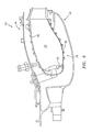
- FIG. 4 is a schematic perspective view of a combustor
- FIG. 5 is a schematic view of a fixture assembly according to one disclosed non-limiting embodiment
- FIG. 6 is a side view of a liner panel
- FIG. 7 is a rear view of the liner panel
- FIG. 8 is a front view of the liner panel
- FIG. 9 is a perspective view of a holder according to one disclosed non-limiting embodiment for the liner panel.
- FIG. 10 is a perspective view of the holder according to one disclosed non-limiting embodiment for the liner panel
- FIG. 11 is a rear view of the holder according to one disclosed non-limiting embodiment for the liner panel
- FIG. 12 is a front view of a holder according to one disclosed non-limiting embodiment for the liner panel
- FIG. 13 is a front view of a holder according to one disclosed non-limiting embodiment for the liner panel illustrating a shadow mask
- FIG. 14 is an expanded perspective view of an uncoated shadowed surface area of the liner panel
- FIG. 15 is a schematic view of a bond coat spray angle with respect to the liner panel
- FIG. 16 is a schematic view of a bond coat spray angle with respect to the liner panel.
- FIG. 17 is a perspective view of a holder for the liner panel illustrating a shadow mask according to another disclosed non-limiting embodiment.
- FIG. 1 schematically illustrates a gas turbine engine 20 .
- the gas turbine engine 20 is disclosed herein as a two-spool turbo fan that generally incorporates a fan section 22 , a compressor section 24 , a combustor section 26 and a turbine section 28 .
- Alternative engine architectures 200 might include an augmentor section 202 and exhaust duct section 204 ( FIG. 2 ) among other systems or features.
- the fan section 22 drives air along a bypass flowpath while the compressor section 24 drives air along a core flowpath for compression and communication into the combustor section 26 then expansion through the turbine section 28 .
- an intermediate spool includes an intermediate pressure compressor (“IPC”) between a Low Pressure Compressor (“LPC”) and a High Pressure Compressor (“HPC”), and an intermediate pressure turbine (“IPT”) between the high pressure turbine (“HPT”) and the Low pressure Turbine (“LPT”).
- IPC intermediate pressure compressor
- LPC Low Pressure Compressor
- HPC High Pressure Compressor
- IPT intermediate pressure turbine
- the combustor section 26 includes a combustion chamber 30 that includes an inner diffuser case 32 and an outer diffuser case 34 .
- a liner assembly 38 includes a dome assembly 36 and a plurality of liner panels 40 that are staggered or otherwise arranged downstream of bulkhead liner panels 42 arranged transverse to the liner panels 40 (also shown in FIG. 4 ).
- a fixture assembly 100 generally includes a base plate 102 and a multiple of holder assemblies 104 which extend therefrom.
- the multiple of holder assemblies 104 extend around and generally parallel to a central axis F of the base plate 102 .
- Each of the multiple of holder assemblies 104 support a workpiece such as the liner panel 40 ( FIGS. 6, 7 and 8 ) in the fixture axial direction as compared to an orientation as configured in the engine.
- each of the multiple of holder assemblies 104 generally includes a support 106 , a backplate 108 and a spray coating shield 110 . It should be understood that various other architectures to receive various other workpieces will also benefit herefrom.
- the support 106 supports the backplate 108 and the spray coating shield 110 on the base plate 102 .
- each support 106 may be received in a slot or other receipt member on the base plate 102 .
- the backplate 108 may be attached to the base plate 102 through one or more fixed rings W ( FIG. 5 ) that are attached and supported on the base plate 102 . That is, the mounts 108 are threaded or otherwise attached directly to the fixed rings W which themselves are supported on the base plate 102 and operate to support the mounts 108 . It should be appreciated that numerous mounts may be supported on each fixed ring W.
- the backplate 108 generally includes one or more standoffs 109 and a backplate 108 ( FIG. 11 ).
- the one or more standoffs 109 are mounted to the support 106 to support the backplate 108 and the spray coating shield 110 .
- the support 106 , the one or more standoffs 109 , the backplate 108 and the spray coating shield 110 may include assembly slots that facilitate tab and slot assembly with tack weld type or other retention.
- the backplate 108 includes a multiple of apertures 112 that correspond with the threaded studs 114 ( FIGS. 7 and 8 ) which extend from a backside of the liner panel 40 .
- Fasteners such as nuts may be threaded to the threaded studs 114 on the backside of the backplate 108 to retain the panel 40 thereto.
- the backplate 108 also includes a multiple of apertures 113 that correspond with a multiple of liner panel apertures 115 in the liner panel 40 ( FIGS. 7 and 8 ).
- the multiple apertures 113 are aligned with the respective liner panel apertures 115 such that spray from the spray operation passes through both the liner panel 40 and the backplate 108 to prevent buildup and reflected spray onto the backside of the liner panel 40 .
- the multiple of apertures 113 may be larger than the liner panel apertures 115 .
- the spray coating shield 110 is mounted to the one or more standoffs 109 and is thereby spaced away from, and extends generally parallel to, the backplate 108 so as to shadow mask ( FIG. 13 ) a shadowed surface area 116 ( FIG. 14 ) on a hot side 117 of the liner panel 40 . That is, the spray coating shield 110 is spaced a predetermined distance from the workpiece relative to the shadowed surface area 116 thereof to mask the shadowed surface area 116 with a “shadow” therefrom.
- the standoffs 109 may be removeable, and/or grouped into clusters that are afixed to the base plate 102 to, for example, prevent the standoffs 109 from being coated with bond coat, or may allow the liner panel 40 to be spaced close together.
- the base plate 102 is rotated about the axis of rotation F (illustrated schematically by arrow R) so the liner panel 40 or workpiece are sprayed with, for example, a thermal barrier coating such as an MCrAlY base coat and a 7YSZ and/or GdZrOx composition topcoats at a predefined angle with respect to the axis of rotation F.
- a thermal barrier coating such as an MCrAlY base coat and a 7YSZ and/or GdZrOx composition topcoats at a predefined angle with respect to the axis of rotation F.
- a base coat is sprayed at ninety (90) degrees with respect to the liner panel 40 to coat the entirety of the liner panel 40 with the base coat.
- a top coat is sprayed at an angle ⁇ ( FIG. 16 ) with respect to the liner panel 40 to mask the shadowed surface area 116 with a “shadow” therefrom. Shadow masking minimizes the potential for the top coat to
- the spray coating shield 110 ′ is of an extended wedge shape to mask the shadowed surface area 116 with respect to the angle ⁇ . It should be understood that various holder assemblies 104 may be mounted to the same base plate 102 .
- This extended shadowed surface area shape 120 or knife shadowed surface area feature is self-maintaining due to the fact that coating does not adhere well with low angle impingement.
- the exposed shadowed surface area of standoffs 109 between the liner panel 40 and standoff 109 that retain the spray coating shield 110 may also be a shadowed surface area or knife shadowed surface area shaped to be self-maintaining as well.
- the spray coating shield 110 ′′ is arranged generally radially and axially relative to the backplate 108 . That is, the spray coating shield may be an L-shaped member attached to the backplate 108 .
- the spray coating shield 110 ′′ may be a thin sheet metal component arranged generally perpendicular to the coated surface of the liner panel 40 to extend toward a direction to the spray so as to as to provide a shadow in the spray coating. More specifically, an example is 16-gage sheet metal spaced 1 ⁇ 8 inch (3.2 mm) from the shadowed surface area of the liner panel 40 to be shadow masked and perpendicular from the coated surface of the liner panel by 1 inch (25 mm).
- the spray coating shield 110 , 110 ′ and 110 ′′ may be removable to further facilitate modularity.
- the spray coating shield 110 , 110 ′ and 110 ′′ may be selectively removed or installed for particular coating operations such as removal for bond coat applications.
- the workpieces are not oriented and configured as in the engine but are rotated so that the short part dimension, is oriented in the circumferential direction and the long dimension is in the fixture axial direction. About four times the number of liner panels 40 can thereby be fixtured to an example 25 inch (635 mm) diameter fixture yet the mask is maintained.
- Powder to part deposition efficiency is increased and cycle time per part is reduced with this fixture configuration. Flexibility is also achieved to combine various workpieces in one spray event. Manual part cleaning operations are also reduced or eliminated.
Abstract
Description
Claims (16)
Priority Applications (1)
| Application Number | Priority Date | Filing Date | Title |
|---|---|---|---|
| US14/772,180 US10151245B2 (en) | 2013-03-06 | 2014-03-06 | Fixturing for thermal spray coating of gas turbine components |
Applications Claiming Priority (3)
| Application Number | Priority Date | Filing Date | Title |
|---|---|---|---|
| US201361773517P | 2013-03-06 | 2013-03-06 | |
| US14/772,180 US10151245B2 (en) | 2013-03-06 | 2014-03-06 | Fixturing for thermal spray coating of gas turbine components |
| PCT/US2014/021250 WO2014138416A1 (en) | 2013-03-06 | 2014-03-06 | Fixturing for thermal spray coating of gas turbine components |
Publications (2)
| Publication Number | Publication Date |
|---|---|
| US20160010197A1 US20160010197A1 (en) | 2016-01-14 |
| US10151245B2 true US10151245B2 (en) | 2018-12-11 |
Family
ID=51491960
Family Applications (1)
| Application Number | Title | Priority Date | Filing Date |
|---|---|---|---|
| US14/772,180 Active 2034-05-12 US10151245B2 (en) | 2013-03-06 | 2014-03-06 | Fixturing for thermal spray coating of gas turbine components |
Country Status (2)
| Country | Link |
|---|---|
| US (1) | US10151245B2 (en) |
| WO (1) | WO2014138416A1 (en) |
Cited By (1)
| Publication number | Priority date | Publication date | Assignee | Title |
|---|---|---|---|---|
| US20190060939A1 (en) * | 2017-08-23 | 2019-02-28 | United Technologies Corporation | Fixture assembly for coating combustor panels |
Families Citing this family (5)
| Publication number | Priority date | Publication date | Assignee | Title |
|---|---|---|---|---|
| CN104375709B (en) * | 2014-12-03 | 2018-01-09 | 京东方科技集团股份有限公司 | Touch control electrode and preparation method thereof, touch-screen, display device |
| DE102015208783A1 (en) * | 2015-05-12 | 2016-11-17 | MTU Aero Engines AG | Covering method for producing a combination of blade tip armor and erosion protection layer |
| US10913091B2 (en) * | 2018-05-14 | 2021-02-09 | The Boeing Company | Templates and methods for controlling application of materials around protuberances |
| CN113981355B (en) * | 2021-09-22 | 2023-10-20 | 中国航发南方工业有限公司 | Split outer ring assembly spraying clamp and method |
| CN114289275A (en) * | 2021-12-26 | 2022-04-08 | 徐州市威固特种玻璃有限公司 | Auxiliary device convenient to smear antifouling compound on ceramic tile surface |
Citations (28)
| Publication number | Priority date | Publication date | Assignee | Title |
|---|---|---|---|---|
| US4284658A (en) | 1979-11-23 | 1981-08-18 | General Motors Corporation | Regenerator seal |
| US4530861A (en) * | 1983-12-19 | 1985-07-23 | General Electric Company | Method and apparatus for masking a surface of a blade member |
| US5323601A (en) | 1992-12-21 | 1994-06-28 | United Technologies Corporation | Individually removable combustor liner panel for a gas turbine engine |
| US5460206A (en) | 1994-02-22 | 1995-10-24 | Db Riley, Inc. | Modular duct liner panel |
| US5565035A (en) * | 1996-03-14 | 1996-10-15 | United Technologies Corporation | Fixture for masking a portion of an airfoil during application of a coating |
| US5697213A (en) | 1995-12-05 | 1997-12-16 | Brewer; Keith S. | Serviceable liner for gas turbine engine |
| US5792267A (en) | 1997-05-16 | 1998-08-11 | United Technologies Corporation | Coating fixture for a turbine engine blade |
| US5879753A (en) | 1997-12-19 | 1999-03-09 | United Technologies Corporation | Thermal spray coating process for rotor blade tips using a rotatable holding fixture |
| US5916638A (en) | 1997-12-19 | 1999-06-29 | United Technologies Corporation | Method for applying a coating to the tip of a flow directing assembly |
| US6224673B1 (en) | 1999-08-11 | 2001-05-01 | General Electric Company | Apparatus for masking turbine components during vapor phase diffusion coating |
| US6252406B1 (en) | 2000-01-12 | 2001-06-26 | Honeywell International Inc. | Programmable event limit detector for computer system power control |
| US6296705B1 (en) | 1999-12-15 | 2001-10-02 | United Technologies Corporation | Masking fixture and method |
| US6401447B1 (en) | 2000-11-08 | 2002-06-11 | Allison Advanced Development Company | Combustor apparatus for a gas turbine engine |
| US20030014888A1 (en) * | 2001-07-23 | 2003-01-23 | Hertz Allen D. | Object, vehicle, structure, or logo styled business card holder |
| US6887529B2 (en) * | 2003-04-02 | 2005-05-03 | General Electric Company | Method of applying environmental and bond coatings to turbine flowpath parts |
| US6974503B2 (en) | 2003-07-30 | 2005-12-13 | General Electric Company | Methods and apparatus for constructing gas turbine engines |
| US7093439B2 (en) | 2002-05-16 | 2006-08-22 | United Technologies Corporation | Heat shield panels for use in a combustor for a gas turbine engine |
| US7546684B2 (en) | 2004-07-27 | 2009-06-16 | General Electric Company | Method for repair and replacement of combustor liner panel |
| US20090324852A1 (en) * | 2008-05-08 | 2009-12-31 | United Technologies Corp. | Systems and methods for forming components with thermal barrier coatings |
| US20100263386A1 (en) | 2009-04-16 | 2010-10-21 | General Electric Company | Turbine engine having a liner |
| US7837843B2 (en) | 2005-07-12 | 2010-11-23 | Praxair S.T. Technology, Inc. | Fixture for use in a coating operation |
| US7914251B2 (en) | 2006-05-16 | 2011-03-29 | Rolls-Royce, Plc | Liner panel |
| US20120132138A1 (en) * | 2010-11-30 | 2012-05-31 | United Technologies Corporation | Dimensionally stable durable thermal spray masking system |
| US8216687B2 (en) | 2004-10-18 | 2012-07-10 | United Technologies Corporation | Thermal barrier coating |
| US8256223B2 (en) | 2007-10-16 | 2012-09-04 | United Technologies Corporation | Ceramic combustor liner panel for a gas turbine engine |
| US8349086B2 (en) | 2004-07-30 | 2013-01-08 | United Technologies Corporation | Non-stick masking fixtures and methods of preparing same |
| US8353259B2 (en) | 2007-08-24 | 2013-01-15 | United Technologies Corporation | Masking fixture for a coating process |
| US20140173896A1 (en) * | 2012-12-21 | 2014-06-26 | United Technologies Corporation | Method and system for holding a combustor panel during coating process |
-
2014
- 2014-03-06 WO PCT/US2014/021250 patent/WO2014138416A1/en active Application Filing
- 2014-03-06 US US14/772,180 patent/US10151245B2/en active Active
Patent Citations (32)
| Publication number | Priority date | Publication date | Assignee | Title |
|---|---|---|---|---|
| US4284658A (en) | 1979-11-23 | 1981-08-18 | General Motors Corporation | Regenerator seal |
| US4530861A (en) * | 1983-12-19 | 1985-07-23 | General Electric Company | Method and apparatus for masking a surface of a blade member |
| US5323601A (en) | 1992-12-21 | 1994-06-28 | United Technologies Corporation | Individually removable combustor liner panel for a gas turbine engine |
| US5460206A (en) | 1994-02-22 | 1995-10-24 | Db Riley, Inc. | Modular duct liner panel |
| US5697213A (en) | 1995-12-05 | 1997-12-16 | Brewer; Keith S. | Serviceable liner for gas turbine engine |
| US5565035A (en) * | 1996-03-14 | 1996-10-15 | United Technologies Corporation | Fixture for masking a portion of an airfoil during application of a coating |
| US5792267A (en) | 1997-05-16 | 1998-08-11 | United Technologies Corporation | Coating fixture for a turbine engine blade |
| US5879753A (en) | 1997-12-19 | 1999-03-09 | United Technologies Corporation | Thermal spray coating process for rotor blade tips using a rotatable holding fixture |
| US5916638A (en) | 1997-12-19 | 1999-06-29 | United Technologies Corporation | Method for applying a coating to the tip of a flow directing assembly |
| US6821564B2 (en) | 1999-08-11 | 2004-11-23 | General Electric Company | Process for masking turbine components during vapor phase diffusion coating |
| US6579567B1 (en) | 1999-08-11 | 2003-06-17 | Nripendra N. Das | Process for selectively masking turbine components during vapor phase diffusion coating |
| US6224673B1 (en) | 1999-08-11 | 2001-05-01 | General Electric Company | Apparatus for masking turbine components during vapor phase diffusion coating |
| US6296705B1 (en) | 1999-12-15 | 2001-10-02 | United Technologies Corporation | Masking fixture and method |
| US6403157B2 (en) | 1999-12-15 | 2002-06-11 | United Technologies Corporation | Masking fixture and method |
| US6252406B1 (en) | 2000-01-12 | 2001-06-26 | Honeywell International Inc. | Programmable event limit detector for computer system power control |
| US6401447B1 (en) | 2000-11-08 | 2002-06-11 | Allison Advanced Development Company | Combustor apparatus for a gas turbine engine |
| US20030014888A1 (en) * | 2001-07-23 | 2003-01-23 | Hertz Allen D. | Object, vehicle, structure, or logo styled business card holder |
| US7093439B2 (en) | 2002-05-16 | 2006-08-22 | United Technologies Corporation | Heat shield panels for use in a combustor for a gas turbine engine |
| US6887529B2 (en) * | 2003-04-02 | 2005-05-03 | General Electric Company | Method of applying environmental and bond coatings to turbine flowpath parts |
| US6974503B2 (en) | 2003-07-30 | 2005-12-13 | General Electric Company | Methods and apparatus for constructing gas turbine engines |
| US7546684B2 (en) | 2004-07-27 | 2009-06-16 | General Electric Company | Method for repair and replacement of combustor liner panel |
| US8349086B2 (en) | 2004-07-30 | 2013-01-08 | United Technologies Corporation | Non-stick masking fixtures and methods of preparing same |
| US8216687B2 (en) | 2004-10-18 | 2012-07-10 | United Technologies Corporation | Thermal barrier coating |
| US7837843B2 (en) | 2005-07-12 | 2010-11-23 | Praxair S.T. Technology, Inc. | Fixture for use in a coating operation |
| US8308916B2 (en) | 2005-07-12 | 2012-11-13 | Praxair S. T. Technology, Inc. | Method for simultaneously coating a plurality of workpieces |
| US7914251B2 (en) | 2006-05-16 | 2011-03-29 | Rolls-Royce, Plc | Liner panel |
| US8353259B2 (en) | 2007-08-24 | 2013-01-15 | United Technologies Corporation | Masking fixture for a coating process |
| US8256223B2 (en) | 2007-10-16 | 2012-09-04 | United Technologies Corporation | Ceramic combustor liner panel for a gas turbine engine |
| US20090324852A1 (en) * | 2008-05-08 | 2009-12-31 | United Technologies Corp. | Systems and methods for forming components with thermal barrier coatings |
| US20100263386A1 (en) | 2009-04-16 | 2010-10-21 | General Electric Company | Turbine engine having a liner |
| US20120132138A1 (en) * | 2010-11-30 | 2012-05-31 | United Technologies Corporation | Dimensionally stable durable thermal spray masking system |
| US20140173896A1 (en) * | 2012-12-21 | 2014-06-26 | United Technologies Corporation | Method and system for holding a combustor panel during coating process |
Cited By (2)
| Publication number | Priority date | Publication date | Assignee | Title |
|---|---|---|---|---|
| US20190060939A1 (en) * | 2017-08-23 | 2019-02-28 | United Technologies Corporation | Fixture assembly for coating combustor panels |
| US11117151B2 (en) * | 2017-08-23 | 2021-09-14 | Raytheon Technologies Corporation | Fixture assembly for coating combustor panels |
Also Published As
| Publication number | Publication date |
|---|---|
| WO2014138416A1 (en) | 2014-09-12 |
| US20160010197A1 (en) | 2016-01-14 |
Similar Documents
| Publication | Publication Date | Title |
|---|---|---|
| US10151245B2 (en) | Fixturing for thermal spray coating of gas turbine components | |
| US20090142548A1 (en) | Air cooled gas turbine components and methods of manufacturing and repairing the same | |
| EP2995864B1 (en) | Film cooling circuit for a combustor liner and method of manufacturing the film cooling circuit | |
| US10317080B2 (en) | Co-swirl orientation of combustor effusion passages for gas turbine engine combustor | |
| US10788210B2 (en) | Single-walled combustor for a gas turbine engine and method of manufacture | |
| EP3032175B1 (en) | A cooled wall assembly for a combustor and method of design | |
| US10247419B2 (en) | Combustor liner panel with a multiple of heat transfer ribs for a gas turbine engine combustor | |
| EP3008387A2 (en) | Conductive panel surface cooling augmentation for gas turbine engine combustor | |
| EP3066322B1 (en) | Coated cooling passage | |
| US20140174091A1 (en) | Repair procedure for a gas turbine engine via variable polarity welding | |
| EP3321586B1 (en) | Gas turbine engine combustor having a coated combustor panel shell and method for manufacturing the combustor | |
| US10669939B2 (en) | Combustor seal for a gas turbine engine combustor | |
| US20200149420A1 (en) | Apparatus and method for masking under platform areas of airfoil components | |
| US10443846B2 (en) | Combustor thermal shield fabrication method | |
| US20200041125A1 (en) | Systems and methods for combustor panel | |
| US20160237950A1 (en) | Backside coating cooling passage | |
| US10823410B2 (en) | Cast combustor liner panel radius for gas turbine engine combustor | |
| EP3318803B1 (en) | Stud arrangement for gas turbine engine combustor | |
| US10670269B2 (en) | Cast combustor liner panel gating feature for a gas turbine engine combustor | |
| US10655853B2 (en) | Combustor liner panel with non-linear circumferential edge for a gas turbine engine combustor |
Legal Events
| Date | Code | Title | Description |
|---|---|---|---|
| AS | Assignment |
Owner name: UNITED TECHNOLOGIES CORPORATION, CONNECTICUT Free format text: ASSIGNMENT OF ASSIGNORS INTEREST;ASSIGNOR:STROCK, CHRISTOPHER W.;REEL/FRAME:036478/0530 Effective date: 20130305 |
|
| STCF | Information on status: patent grant |
Free format text: PATENTED CASE |
|
| AS | Assignment |
Owner name: RAYTHEON TECHNOLOGIES CORPORATION, MASSACHUSETTS Free format text: CHANGE OF NAME;ASSIGNOR:UNITED TECHNOLOGIES CORPORATION;REEL/FRAME:054062/0001 Effective date: 20200403 |
|
| AS | Assignment |
Owner name: RAYTHEON TECHNOLOGIES CORPORATION, CONNECTICUT Free format text: CORRECTIVE ASSIGNMENT TO CORRECT THE AND REMOVE PATENT APPLICATION NUMBER 11886281 AND ADD PATENT APPLICATION NUMBER 14846874. TO CORRECT THE RECEIVING PARTY ADDRESS PREVIOUSLY RECORDED AT REEL: 054062 FRAME: 0001. ASSIGNOR(S) HEREBY CONFIRMS THE CHANGE OF ADDRESS;ASSIGNOR:UNITED TECHNOLOGIES CORPORATION;REEL/FRAME:055659/0001 Effective date: 20200403 |
|
| MAFP | Maintenance fee payment |
Free format text: PAYMENT OF MAINTENANCE FEE, 4TH YEAR, LARGE ENTITY (ORIGINAL EVENT CODE: M1551); ENTITY STATUS OF PATENT OWNER: LARGE ENTITY Year of fee payment: 4 |
|
| AS | Assignment |
Owner name: RTX CORPORATION, CONNECTICUT Free format text: CHANGE OF NAME;ASSIGNOR:RAYTHEON TECHNOLOGIES CORPORATION;REEL/FRAME:064714/0001 Effective date: 20230714 |