EP4394401A1 - Impedanzmessvorrichtung - Google Patents
Impedanzmessvorrichtung Download PDFInfo
- Publication number
- EP4394401A1 EP4394401A1 EP22861129.9A EP22861129A EP4394401A1 EP 4394401 A1 EP4394401 A1 EP 4394401A1 EP 22861129 A EP22861129 A EP 22861129A EP 4394401 A1 EP4394401 A1 EP 4394401A1
- Authority
- EP
- European Patent Office
- Prior art keywords
- voltage
- current
- disconnection detection
- coupling capacitor
- terminals
- Prior art date
- Legal status (The legal status is an assumption and is not a legal conclusion. Google has not performed a legal analysis and makes no representation as to the accuracy of the status listed.)
- Pending
Links
Images


Classifications
-
- G—PHYSICS
- G01—MEASURING; TESTING
- G01R—MEASURING ELECTRIC VARIABLES; MEASURING MAGNETIC VARIABLES
- G01R27/00—Arrangements for measuring resistance, reactance, impedance, or electric characteristics derived therefrom
- G01R27/02—Measuring real or complex resistance, reactance, impedance, or other two-pole characteristics derived therefrom, e.g. time constant
-
- G—PHYSICS
- G01—MEASURING; TESTING
- G01R—MEASURING ELECTRIC VARIABLES; MEASURING MAGNETIC VARIABLES
- G01R31/00—Arrangements for testing electric properties; Arrangements for locating electric faults; Arrangements for electrical testing characterised by what is being tested not provided for elsewhere
- G01R31/36—Arrangements for testing, measuring or monitoring the electrical condition of accumulators or electric batteries, e.g. capacity or state of charge [SoC]
- G01R31/389—Measuring internal impedance, internal conductance or related variables
-
- G—PHYSICS
- G01—MEASURING; TESTING
- G01R—MEASURING ELECTRIC VARIABLES; MEASURING MAGNETIC VARIABLES
- G01R31/00—Arrangements for testing electric properties; Arrangements for locating electric faults; Arrangements for electrical testing characterised by what is being tested not provided for elsewhere
- G01R31/36—Arrangements for testing, measuring or monitoring the electrical condition of accumulators or electric batteries, e.g. capacity or state of charge [SoC]
- G01R31/382—Arrangements for monitoring battery or accumulator variables, e.g. SoC
- G01R31/3835—Arrangements for monitoring battery or accumulator variables, e.g. SoC involving only voltage measurements
-
- G—PHYSICS
- G01—MEASURING; TESTING
- G01R—MEASURING ELECTRIC VARIABLES; MEASURING MAGNETIC VARIABLES
- G01R31/00—Arrangements for testing electric properties; Arrangements for locating electric faults; Arrangements for electrical testing characterised by what is being tested not provided for elsewhere
- G01R31/50—Testing of electric apparatus, lines, cables or components for short-circuits, continuity, leakage current or incorrect line connections
- G01R31/54—Testing for continuity
Definitions
- the present invention relates to impedance measuring devices, and to a four-terminal impedance measuring device having a disconnection detection function.
- Patent Literature 1 Japanese Patent No. 4695920
- the present invention has been made in view of the above-stated problem, and an object of the present invention is to allow charging of a coupling capacitor and detection of disconnection in a short time.
- an impedance measuring device including: a measurement unit that measures a voltage, generated between contact terminals that respectively contact both terminals of a measurement target object by an alternating current supplied to the measurement target object, and determines an internal impedance of the measurement target object; a current source for disconnection detection that supplies an alternating current for disconnection detection to a current path between the measurement unit and the measurement target object via a coupling capacitor; and a charging acceleration unit connected between the coupling capacitor and the current source for disconnection detection to charge the coupling capacitor when the voltage between both the terminals of the current source for disconnection detection exceeds a prescribed voltage range.
- the impedance measuring device According to the impedance measuring device according to the present invention, it becomes possible to charge the coupling capacitor and to detect disconnection in a short time.
- the battery tester 200 is a device that supplies an alternating current Im for measurement to the battery 230 from a current source for measurement 210, measures in a measurement unit 220 a voltage Vm generated between contact terminals Hp and Lp that respectively contact both terminals of the battery 230 by the alternating current Im, and measures an internal impedance Z of the battery 230 based on the current Im supplied to the battery 230 and the measured voltage Vm.
- the battery tester 200 supplies an alternating current Id for disconnection detection to the current path 201 between the measurement unit 220 and the battery 230 from a current supply unit for disconnection detection 240 via a coupling capacitor C3, and measures in the measurement unit 220 a voltage Vd, generated between the contact terminals Hp and Lp that respectively contact both terminals of the battery 230 by the alternating current Id for disconnection detection, to detect disconnection of the current path 201.
- the high voltage-side source terminal Hc is connected to one end of the current source for measurement 210 via a coupling capacitor C1. Another end of the current source for measurement 210 and the low voltage-side source terminal Lc are connected to a ground GND1 that is a source-side reference potential.
- the high voltage-side sense terminal Hp is connected to the measurement unit 220 via a coupling capacitor C2 and to the current supply unit for disconnection detection 240 via the coupling capacitor C3.
- the low voltage-side sense terminal Lp is connected to a ground GND2 that is a sense-side reference potential.
- the reference potential of component members disposed on the sense side, such as the measurement unit 220 and the current supply unit for disconnection detection 240, is also the ground GND2.
- the ground GND1 that is the reference potential on the source side and the ground GND2 that is the reference potential on the sense side are electrically separated.
- a signal input into the measurement unit 220 via the coupling capacitor C2 is amplified by a non-inverting amplifier circuit in an operational amplifier OP1 and input into an arithmetic unit 221.
- a non-inverting input terminal of the operational amplifier OP1 is connected to an input of the measurement unit 220, an inverting terminal of the operational amplifier OP1 is connected to one end of a resistor R1 and one end of a resistor R2, and an output terminal of the operational amplifier OP1 is connected to another end of the resistor R1 and the arithmetic unit 221. Another end of the resistor R2 is connected to the ground GND2.
- the arithmetic unit 221 includes two lock-in amplifiers, and, by performing synchronization detection at the frequencies of the respective alternating currents supplied from the current source for measurement 210 and the current supply unit for disconnection detection 240, measures the voltage Vm generated between the contact terminals Hp and Lp that respectively contact both the terminals of the battery 230 by the alternating current Im for measurement, and the voltage Vd generated between the contact terminals Hp and Lp that respectively contact both the terminals of the battery 230 by the alternating current Id for disconnection detection. Also, based on the alternating current Im for measurement and the voltage Vm, the internal impedance Z of the battery 230 is calculated. By comparing the voltage Vd with a reference value, disconnection of the current path 201 between the measurement unit 220 and the battery 230 is detected.
- an absolute value of the voltage between both the terminals of the battery 230 is generally larger than the absolute value of the compliance voltage. It is necessary, therefore, to charge the coupling capacitor C3 so that the voltage between both the terminals of the current source for disconnection detection 241 is within the compliance voltage range before supplying the current Id for disconnection detection.
- the charging acceleration unit 242 monitors the voltage between both the terminals of the current source for disconnection detection 241, that is, the voltage Va at a point a, and when the voltage Va exceeds a prescribed voltage range, direct current is supplied from the charging acceleration unit 242 to accelerate the charging of the coupling capacitor C3, so as to shorten the time until disconnection detection becomes possible.
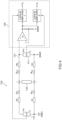
- FIG. 2 shows an exemplary configuration of the charging acceleration unit 242.
- the charging acceleration unit 242 has a hysteresis comparator 245 for a positive power source and a hysteresis comparator 246 for a negative power source.
- the hysteresis comparator 245 for a positive power source operates when the battery 230 for positive voltage (the battery connected as shown in FIG. 1 ) is connected and charges the coupling capacitor C3.
- the hysteresis comparator 246 for a negative power source operates when the battery 230 for negative voltage (the battery connected reversely to the case shown in FIG. 1 ) is connected and charges the coupling capacitor C3.
- the hysteresis comparator 245 for a positive power source includes an operational amplifier OP2, a diode D1, and three resistors R11, R12, and R13.
- An inverting terminal of the operational amplifier OP2 is connected to an output of the charging acceleration unit 242 and an anode of the diode D1.
- a non-inverting terminal of the operational amplifier OP2 is connected to one end of each of the three resistors R11, R12, and R13.
- An output terminal of the operational amplifier OP2 is connected to a cathode of the diode D1 and another end of the resistor R13.
- Another end of the resistor R11 is connected to the ground GND2, and another end of the resistor R12 is connected to a positive power source +V.
- Hysteresis characteristics of the hysteresis comparator 245 (low voltage-side threshold voltage and high voltage-side threshold voltage) are set depending on the magnitude of the three resistors R11, R12,
- the hysteresis comparator 246 for a negative power source has a configuration symmetrical to the hysteresis comparator 245 for a positive power source.
- the hysteresis comparator 246 for a negative power source includes an operational amplifier OP3, a diode D2, and three resistors R21, R22, and R23.
- An inverting terminal of the operational amplifier OP3 is connected to the output of the charging acceleration unit 242 and a cathode of the diode D2.
- a non-inverting terminal of the operational amplifier OP3 is connected to one end of each of the three resistors R21, R22, and R23.
Landscapes
- Physics & Mathematics (AREA)
- General Physics & Mathematics (AREA)
- Testing Of Short-Circuits, Discontinuities, Leakage, Or Incorrect Line Connections (AREA)
- Measurement Of Resistance Or Impedance (AREA)
Applications Claiming Priority (2)
| Application Number | Priority Date | Filing Date | Title |
|---|---|---|---|
| JP2021138307A JP7569763B2 (ja) | 2021-08-26 | 2021-08-26 | インピーダンス測定装置 |
| PCT/JP2022/030277 WO2023026839A1 (ja) | 2021-08-26 | 2022-08-08 | インピーダンス測定装置 |
Publications (2)
| Publication Number | Publication Date |
|---|---|
| EP4394401A1 true EP4394401A1 (de) | 2024-07-03 |
| EP4394401A4 EP4394401A4 (de) | 2025-09-17 |
Family
ID=85323103
Family Applications (1)
| Application Number | Title | Priority Date | Filing Date |
|---|---|---|---|
| EP22861129.9A Pending EP4394401A4 (de) | 2021-08-26 | 2022-08-08 | Impedanzmessvorrichtung |
Country Status (5)
| Country | Link |
|---|---|
| US (1) | US20250334640A1 (de) |
| EP (1) | EP4394401A4 (de) |
| JP (1) | JP7569763B2 (de) |
| CN (1) | CN117897624A (de) |
| WO (1) | WO2023026839A1 (de) |
Families Citing this family (1)
| Publication number | Priority date | Publication date | Assignee | Title |
|---|---|---|---|---|
| JP2025110119A (ja) * | 2024-01-15 | 2025-07-28 | 日置電機株式会社 | インピーダンス測定装置およびインピーダンス測定方法 |
Family Cites Families (12)
| Publication number | Priority date | Publication date | Assignee | Title |
|---|---|---|---|---|
| JPH0442784Y2 (de) * | 1984-12-24 | 1992-10-09 | ||
| JPS6454423U (de) * | 1987-09-29 | 1989-04-04 | ||
| JPH06104660A (ja) * | 1992-09-17 | 1994-04-15 | Fujitsu Ltd | 交流増幅回路 |
| JPH06130120A (ja) * | 1992-10-14 | 1994-05-13 | Matsushita Electron Corp | 半導体集積回路の試験方法 |
| JPH08153157A (ja) * | 1994-11-28 | 1996-06-11 | Nippondenso Co Ltd | 光学的情報読み取り装置 |
| JP3562623B2 (ja) | 1998-10-07 | 2004-09-08 | 横河電機株式会社 | 計測装置 |
| IT1305651B1 (it) * | 1998-12-16 | 2001-05-15 | St Microelectronics Srl | Circuito anti-pop per amplificatori ac |
| JP4695920B2 (ja) | 2005-05-19 | 2011-06-08 | 日置電機株式会社 | インピーダンス測定装置 |
| JP4735250B2 (ja) | 2005-12-28 | 2011-07-27 | 横河電機株式会社 | 計測装置 |
| JP4913458B2 (ja) | 2006-03-27 | 2012-04-11 | 日置電機株式会社 | 測定装置 |
| JP2009300343A (ja) | 2008-06-17 | 2009-12-24 | Yokogawa Electric Corp | Icテスタ及びコンタクトチェック方法 |
| JP7154958B2 (ja) * | 2018-11-06 | 2022-10-18 | 日置電機株式会社 | インピーダンス測定装置 |
-
2021
- 2021-08-26 JP JP2021138307A patent/JP7569763B2/ja active Active
-
2022
- 2022-08-08 US US18/684,729 patent/US20250334640A1/en active Pending
- 2022-08-08 CN CN202280058045.7A patent/CN117897624A/zh active Pending
- 2022-08-08 WO PCT/JP2022/030277 patent/WO2023026839A1/ja not_active Ceased
- 2022-08-08 EP EP22861129.9A patent/EP4394401A4/de active Pending
Also Published As
| Publication number | Publication date |
|---|---|
| JP7569763B2 (ja) | 2024-10-18 |
| JP2023032275A (ja) | 2023-03-09 |
| CN117897624A (zh) | 2024-04-16 |
| EP4394401A4 (de) | 2025-09-17 |
| US20250334640A1 (en) | 2025-10-30 |
| WO2023026839A1 (ja) | 2023-03-02 |
Similar Documents
| Publication | Publication Date | Title |
|---|---|---|
| US20050268000A1 (en) | Accessory identifier in an electronic device | |
| US11675015B1 (en) | Battery cell analyzer | |
| JP2004294437A (ja) | 電子バッテリテスタ | |
| JP2004191373A (ja) | 電子バッテリテスタ | |
| US20160274173A1 (en) | Presence and Operability Test of a Decoupling Capacitor | |
| US8901891B2 (en) | Voltage polarity determination circuit and charge amount measurement circuit | |
| CN102064597A (zh) | 蓄电装置 | |
| EP4394401A1 (de) | Impedanzmessvorrichtung | |
| US9383400B2 (en) | Critical capacitor built in test | |
| TWI505530B (zh) | 電池容量檢測系統 | |
| US9709606B1 (en) | Smart voltmeter for electric fence | |
| TW202238150A (zh) | 異物偵測方法及具有異物偵測功能之電源端 | |
| US20030042910A1 (en) | Method and circuit for electrical testing of isolation resistance of large capacitance network | |
| KR102369138B1 (ko) | 콘덴서의 절연 저항 측정 장치 | |
| US10944259B2 (en) | System and method for over voltage protection in both positive and negative polarities | |
| US10955462B2 (en) | Apparatus and method for frequency characterization of an electronic system | |
| CN213122226U (zh) | 一种无线耳机充电盒的检测电路、充电盒和无线耳机 | |
| JP2014010028A (ja) | 電池のインピーダンス測定装置およびその測定方法 | |
| CN110221644B (zh) | 一种芯片及其外置rset电阻开路监测电路 | |
| KR101142459B1 (ko) | 절연파괴 측정회로 | |
| CN216748022U (zh) | 用于隔离电源的隔离检测电路 | |
| CN207851235U (zh) | Ic短路保护电压阈值检测电路 | |
| JP2977415B2 (ja) | バッテリのピーク電圧およびディップ電圧検出装置 | |
| JPH11281688A (ja) | 定電流源および抵抗測定装置 | |
| JP2012233843A (ja) | インピーダンス測定装置 |
Legal Events
| Date | Code | Title | Description |
|---|---|---|---|
| STAA | Information on the status of an ep patent application or granted ep patent |
Free format text: STATUS: THE INTERNATIONAL PUBLICATION HAS BEEN MADE |
|
| PUAI | Public reference made under article 153(3) epc to a published international application that has entered the european phase |
Free format text: ORIGINAL CODE: 0009012 |
|
| STAA | Information on the status of an ep patent application or granted ep patent |
Free format text: STATUS: REQUEST FOR EXAMINATION WAS MADE |
|
| 17P | Request for examination filed |
Effective date: 20240222 |
|
| AK | Designated contracting states |
Kind code of ref document: A1 Designated state(s): AL AT BE BG CH CY CZ DE DK EE ES FI FR GB GR HR HU IE IS IT LI LT LU LV MC MK MT NL NO PL PT RO RS SE SI SK SM TR |
|
| DAV | Request for validation of the european patent (deleted) | ||
| DAX | Request for extension of the european patent (deleted) | ||
| A4 | Supplementary search report drawn up and despatched |
Effective date: 20250814 |
|
| RIC1 | Information provided on ipc code assigned before grant |
Ipc: G01R 27/02 20060101AFI20250808BHEP Ipc: G01R 31/54 20200101ALI20250808BHEP Ipc: G01R 31/56 20200101ALI20250808BHEP Ipc: G01R 31/389 20190101ALI20250808BHEP |