EP4394301A2 - Kühlplatte für eine schmelzvorrichtung - Google Patents
Kühlplatte für eine schmelzvorrichtung Download PDFInfo
- Publication number
- EP4394301A2 EP4394301A2 EP24175526.3A EP24175526A EP4394301A2 EP 4394301 A2 EP4394301 A2 EP 4394301A2 EP 24175526 A EP24175526 A EP 24175526A EP 4394301 A2 EP4394301 A2 EP 4394301A2
- Authority
- EP
- European Patent Office
- Prior art keywords
- cooling panel
- wall
- baffles
- walls
- melter
- Prior art date
- Legal status (The legal status is an assumption and is not a legal conclusion. Google has not performed a legal analysis and makes no representation as to the accuracy of the status listed.)
- Granted
Links
Images






Classifications
-
- C—CHEMISTRY; METALLURGY
- C03—GLASS; MINERAL OR SLAG WOOL
- C03B—MANUFACTURE, SHAPING, OR SUPPLEMENTARY PROCESSES
- C03B5/00—Melting in furnaces; Furnaces so far as specially adapted for glass manufacture
- C03B5/16—Special features of the melting process; Auxiliary means specially adapted for glass-melting furnaces
- C03B5/42—Details of construction of furnace walls, e.g. to prevent corrosion; Use of materials for furnace walls
- C03B5/44—Cooling arrangements for furnace walls
-
- C—CHEMISTRY; METALLURGY
- C03—GLASS; MINERAL OR SLAG WOOL
- C03B—MANUFACTURE, SHAPING, OR SUPPLEMENTARY PROCESSES
- C03B5/00—Melting in furnaces; Furnaces so far as specially adapted for glass manufacture
- C03B5/16—Special features of the melting process; Auxiliary means specially adapted for glass-melting furnaces
- C03B5/235—Heating the glass
- C03B5/2356—Submerged heating, e.g. by using heat pipes, hot gas or submerged combustion burners
-
- C—CHEMISTRY; METALLURGY
- C03—GLASS; MINERAL OR SLAG WOOL
- C03B—MANUFACTURE, SHAPING, OR SUPPLEMENTARY PROCESSES
- C03B2211/00—Heating processes for glass melting in glass melting furnaces
- C03B2211/20—Submerged gas heating
- C03B2211/22—Submerged gas heating by direct combustion in the melt
Definitions
- SCM submerged combustion melting
- a typical submerged combustion melter has a floor and a vertical burner passage extending through the floor. A burner positioned within the burner passage is submerged in the molten glass.
- part or all of the melter's floor, walls, or roof can be fluid-cooled.
- a portion of the melter's floor, walls, or roof that contacts the molten glass can include a refractory material in order to withstand the high temperatures.
- Another portion of the melter's floor, walls, or roof can include the fluid-cooling.
- the present disclosure embodies a number of aspects that can be implemented separately from or in combination with each other.
- a cooling panel for a melter that includes first and second outer walls and a plurality of side walls coupled to the first and second outer walls, defining an interior space, and a plurality of baffles disposed in the interior space, where each baffle includes a plurality of projections.
- Each of the first and second outer walls has a plurality of openings. Respective openings and projections fit together and are connected from outside of the cooling panel so that the outer walls and the baffles are fixed together, and the side walls are fixed to the outer walls so that the cooling panel is fluid-tight.
- a cooling panel for a melter that has first and second outer walls and a plurality of side walls, defining an interior space, and a plurality of baffles disposed in the interior space and dividing the interior space into a plurality of rows wherein each row has a width W.
- Each baffle has first and second longitudinal surfaces and an open transverse surface. Each open transverse surface of each baffle is spaced away from an adjacent side wall by a distance D that is 70% to 80% of the width W of each row.
- a method of forming a cooling panel having some or all of the features discussed herein.
- the method includes receiving a plurality of side walls, first and second outer walls each having a plurality of openings, and a plurality of baffles each having a plurality of projections; connecting the first and second walls with the plurality of baffles disposed between the outer walls; and connecting the side walls to the first and second outer walls to fix the sides walls to the outer walls and so that the cooling panel is fluid-tight.
- a cooling panel for a melter that includes first and second outer walls and a plurality of side walls coupled to the first and second outer walls, defining an interior space, where the first outer wall includes a plurality of inwardly-facing first grooves, and the second outer wall includes a plurality of inwardly-facing second grooves parallel with the first grooves; and a plurality of baffles disposed in the interior space and carried by the first grooves and the second grooves; wherein a first set of the first grooves and the second grooves extends a length of the cooling panel, and a second set of the first grooves and the second grooves partially extends the length of the cooling panel, and wherein the first set and the second set alternate to create a serpentine fluid flow path in the interior space.
- a cooling panel for a glass melter is provided that is better able to withstand the harsh conditions of the melter than prior cooling panels.
- a melter having at least one cooling panel is disclosed.
- Each cooling panel requires less time than conventionally fabricated panels to position internal baffles, assemble and weld each panel, and reduces the likelihood of error.
- Projections on each baffle fit into corresponding openings in outside walls and can be welded using plug welds. No fillet welds are required inside the cooling panels because each baffle can be welded from the outside using plug welds.
- Each outside wall, side wall, and baffle can be laser cut with the required openings and projections and require no layout time.
- each cooling panel can include fluid flow paths that can be configured to reduce stagnant areas of fluid flow and minimize surface hot spots on the hot side of each cooling panel.
- the fluid flow paths can also be configured to reduce pressure drop of the coolant.
- Each cooling panel can include an inlet at the bottom and an outlet at the top, which reduces risk of developing an air pocket in the top of the panel.
- each cooling panel can be configured to be the same size and/or interchangeable, which also allows different configurable locations for an access door and/or melter exits.
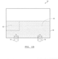
- the molten material 16 in the melter 10 can typically exist in a liquid or semi-liquid state; however, a portion of the molten material 16 that flows closer to the floors, walls, or roof of the melter 10 can become a solid (or at least a very viscous state) because of its lower temperature, due to a cooling effect from the floors, walls, or roof, than the first portion of the molten material 16.
- the solidified material (which can be glass) can comprise a solid or frozen material layer 18 that can be coupled to the floors, walls and roof (e.g., at least one cooling panel 12).
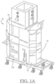
- the melter 10 can comprise at least one cooling panel 12 configured to both provide structure to the melter and to cool a portion of the molten material 16 and form the frozen material layer 18 coupled to each cooling panel 12.
- the floor, the walls, and the roof of the melter 10 can include interchangeable cooling panels, as depicted in FIG. 1A . It is contemplated that the melter 10 may be comprised entirely of multiple cooling panels 12 or may comprise only one or several cooling panels 12.
- FIG. 2B illustrates the second outer wall 22 having a perimeter 42 and a plurality of second openings 44.
- the side walls 34, 36, 38, 40 can also be configured to be coupled (e.g., welded) to the second outer wall 22 around and/or proximate to the perimeter 42.
- first openings 28 and the second openings 44 are depicted as holes or slots, although other configurations may be included. Even though the first openings 28 and the second openings 44 are depicted as having a circular cross-section or as slots, they could also be configured with a variety of cross-sections and/or shapes, including oval, rectangular, square, triangular, other types of polygons, or the like.
- each cooling panel 12 can include at least one baffle 24.
- Each baffle 24 can have a first side 46 with respective first projections 48 and an opposing second side 50 with respective second projections 52.
- the first and second projections 48, 52 are depicted as tabs extending from both the first and second sides 46, 50 of the baffle 24, although the first and second projections 48, 52 may be configured in other ways.
- the first projections 48 extend from the first side 46 of the baffle 24 and are configured to fit in respective first openings 28 of the first outer wall 20, and the second projections 52 extend from the second side 50 of the baffle 24 and are configured to fit in respective second openings 44 of the second outer wall 22.
- the projections 48, 52 could comprise other configurations, for example posts, studs, screws, rivets, slugs, bolts, welds, welded pieces, or the like.
- the openings 28, 44 and the projections 48, 52 can be configured to fit together (e.g., a loose fit, an interference fit, and so forth) and connect from outside of the cooling panel 12, requiring no welds (e.g., fillet welds) within the cooling panel 12.
- the first and second outer walls 20, 22 and the baffles 24 can be fixed (e.g., coupled) together, and the side walls 34, 36, 38, 40 can be fixed to the first and second outer walls 20, 22 so that the cooling panel 12 is fluid-tight.
- each baffle 24 can comprise a pair of longitudinal surfaces including a first longitudinal surface 54 and an opposing second longitudinal surface 56.
- Each baffle 24 can also include an open transverse surface 58 configured to not be coupled to anything else (e.g., exposed to coolant). While the open transverse surface 58 in FIG. 2C is shown at the bottom of the baffle 24, it will be appreciated that the open transverse surface 58 could also be located at the top of the baffle 24.
- the first and second outer walls 20, 22, the side walls 34, 36, 38, 40, and the baffles 24 can define an interior space 62 in which the coolant can flow through a serpentine fluid flow path 60.
- the baffles 24 function to divide the interior space 62 into a plurality of rows (e.g., row 64), where each row can be parallel with a longitudinal axis A and can have a width W.
- the width W can be between baffles 24 or between one baffle 24 and an adjacent side wall 36, 40.
- the width W between baffles 24 may be the same as the width W between the one baffle 24 and the adjacent side wall 36, 40.
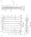
- FIGS. 3A-3D illustrate an embodiment of a cooling panel 12 showing one outer wall (e.g., first outer wall 20) including side walls 34, 36, 38, 40 coupled to the outer wall around a perimeter (e.g., perimeter 26) of the outer wall.
- the plurality of side walls 34, 36, 38, 40, along with the first outer wall 20 and the second outer wall 22, can define an interior space 62 with fluid passages 66 through which a coolant can flow.
- the fluid passages 66 can be aligned and/or correspond with a respective row 64.
- FIG. 3A illustrates one arrangement of the openings 28 in the first outer wall 20, where the openings 28 are arranged parallel to longitudinal axis A and configured to be coupled with respective projections 48, 52 of each baffle 24.
- the second outer wall 22 and the baffles 24 are shown removed in FIG. 3A .
- FIG. 3B illustrates a plurality of baffles 24 coupled to the first outer wall 20, where the first projections 48 are coupled with respective first openings 28.
- the first outer wall 20, and the side walls 34, 36, 38, 40 define a plurality of fluid passages 66 when the second outer wall 22 is also coupled to the baffles 24 and the side walls 34, 36, 38, 40.
- the outer wall shown in FIGS. 3A through 3D may be either the first outer wall 20 and/or the second outer wall 22. Additionally, the second outer wall 22 is shown removed in FIG. 3B .
- the cooling panel 12 can be formed so that the first and second openings 28, 44 and the projections 48, 52 fit together, respectively, in order to secure the first and second outer walls 20, 22 to the baffles 24.
- the first and second openings 28, 44 and the projections 48, 52 can be held together by clamps until welds have been made and connected together from outside of the cooling panel 12 so that no interior welds are necessary within the cooling panel 12.
- a cooling panel would typically be constructed such that baffles were welded, for example stitch welded or intermittently welded, along a joint between a respective baffle and one of the first and second outer walls from within the interior space. These internal welds have been necessary to hold the baffles in place prior to attaching the first and/or second outer walls.
- the first and second outer walls 20, 22 and the baffles 24 can be fitted together without needing to internally weld either of the first and second outer walls to the baffles 24 before also fitting the other of the first and second outer walls 20, 22 to the baffles 24.
- This can save time and cost in construction.
- This construction also can reduce the chance for any errors in positioning the first and second outer walls 20, 22 and the baffles 24 together. All welds can be made from outside the cooling panel 12 such that a liquid-tight joint results. Additionally, the first and second outer walls 20, 22 and the baffles 24 can be more easily cut, including being laser-cut, to the correct geometries.
- the temperature measurements within the various pipes, conduits, or the like can provide an indirect temperature measurement of the temperature of the coolant when it is in the cooling panel 12.
- the cooling panel 12 can also be constructed to include various temperature sensors (e.g., a thermocouple) that directly detect and measure, for example, the temperature of the molten material 16, a surface of the molten material 16, the frozen material layer 18, the cooling panel 12, and/or the temperature of the coolant.
- the first and second outer walls 120, 122, the side walls 134, 136, 138, 140, and the baffles 124 do not require external welds.
- Additive manufacturing may provide a cooling panel 112 with a geometry that may not be possible if other fabrication methods, for example welding, were used.
- the baffles 24, 124 can alternate such that one baffle 24, 124 has the respective distance D spaced away from a first side wall 34, 38, 134, 138, and an adjacent baffle 24, 124 has the respective distance D spaced away from a second side wall 34, 38, 134, 138 (e.g., distal from the first side wall).
- the distance D between the side walls 34, 38, 134, 138 can be manufactured such that it is substantially the same between each baffle 24, 124 and each respective side wall 34, 38, 134, 138 so that it is approximately 70% to 80% of the width W of each row 64, 164, including all ranges, subranges, values therebetween, and endpoints.
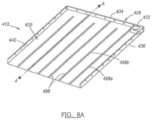
- first grooves 498 can extend a length of the first outer wall 420, and some of the first grooves 498 can extend only partially the length of the first outer wall 420.
- first grooves 498 are shown alternatively between first grooves 498a that extend the full length of the first outer wall 420 and first grooves 498b that extend only partially the length of the first outer wall 420. It will be appreciated that the first grooves 498 may include other configurations.
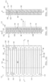
- FIGS. 8A-8D illustrate an embodiment of a cooling panel 412 showing a first outer wall 420 and side walls 434, 436, 438, 440 coupled to the first outer wall 420 around a perimeter 426 of the first outer wall 420.
- the plurality of side walls 434, 436, 438, 440, along with the first outer wall 420 and the second outer wall 422, can define an interior space 462 with fluid passages 466 through which a coolant can flow in a generally serpentine fluid flow path 460.
- the fluid passages 466 can be aligned and/or correspond with a respective row 464.
- the baffles 424 may be positioned between the first outer wall 420 and the second outer wall 422 by inserting each baffle 424 into the side of the cooling panel 412 where the side wall 438 is not yet coupled.
- the baffles 424 can be inserted or slid into a respective first groove 498 and a corresponding second groove 499 until the baffle 424 reaches the end of the respective first groove 498 and second groove 499 and/or the side wall 434.
- the side wall e.g., side wall 438) may then be coupled to the first outer wall 420, the second outer wall 422, and side walls 436, 440, and the baffles 424 can form the serpentine fluid flow path 460. It will be appreciated that other arrangements and fluid flow paths may be implemented other than a serpentine-type configuration.
- the cooling panel 412 may also include the coolant inlet 430 and the coolant outlet 432 for passing a coolant into and from the cooling panel 412.
- the method 500 can include the first and second openings 28, 44 including slots, and the projections 48, 52 including tabs, so that a plurality of first projections 48 extend from the first side 46 of each baffle 24 to fit in the openings 28 of the first outer wall 20 and so that a plurality of projections 52 extend from the second side 50 of each baffle 24 to fit in the openings 44 of the second outer wall 22.
- the first and second openings 28, 44 and the respective projections 48, 52 can be plug welded together, respectively, from outside of the cooling panel 12.
- the side walls 34, 36, 38, 40 can be fillet welded to both of the first and second outer walls 20, 22, also from outside the cooling panel 12.
- the final geometry created can be a single monolithic structure that does not include any welds, seams, or other joint areas between parts.
- Some examples of additive manufacturing include three dimensional (3D) printing, rapid prototyping, powder bed fusion, sheet lamination, directed energy deposition, or a combination thereof. It will be appreciated that the final geometry can include various parts that are not additively manufactured and/or are not part of the single monolithic structure. These parts can be formed using traditional manufacturing techniques, such as cutting and/or welding, while other parts are additively manufactured using the material build up process.
- the melter 10 includes fourteen cooling panels 12, 112, 212, 312, 412 in addition to the ten identical cooling panels 12, 112, 212, 312, 412 that are in accordance with various aspects of this disclosure; however, each of the fourteen cooling panels 12, 112, 212, 312, 412 are unique to any other cooling panels 12, 112, 212, 312, 412 within the melter 10 in some way. It will be appreciated that all cooling panels 12, 112, 212, 312, 412 in the melter 10 could be similar, but not identical, to each other.
Landscapes
- Chemical & Material Sciences (AREA)
- Engineering & Computer Science (AREA)
- Materials Engineering (AREA)
- Organic Chemistry (AREA)
- Combustion & Propulsion (AREA)
- Furnace Housings, Linings, Walls, And Ceilings (AREA)
- Lining Or Joining Of Plastics Or The Like (AREA)
- Gasification And Melting Of Waste (AREA)
- Waste-Gas Treatment And Other Accessory Devices For Furnaces (AREA)
- Butt Welding And Welding Of Specific Article (AREA)
- Laser Beam Processing (AREA)
- Standing Axle, Rod, Or Tube Structures Coupled By Welding, Adhesion, Or Deposition (AREA)
- Connection Of Plates (AREA)
- Muffle Furnaces And Rotary Kilns (AREA)
Applications Claiming Priority (3)
| Application Number | Priority Date | Filing Date | Title |
|---|---|---|---|
| US16/590,065 US11390551B2 (en) | 2019-10-01 | 2019-10-01 | Cooling panel for a melter |
| PCT/US2020/053204 WO2021067227A1 (en) | 2019-10-01 | 2020-09-29 | Cooling panel for a melter |
| EP20797587.1A EP4038030B1 (de) | 2019-10-01 | 2020-09-29 | Kühlplatte für einen schmelzer |
Related Parent Applications (2)
| Application Number | Title | Priority Date | Filing Date |
|---|---|---|---|
| EP20797587.1A Division-Into EP4038030B1 (de) | 2019-10-01 | 2020-09-29 | Kühlplatte für einen schmelzer |
| EP20797587.1A Division EP4038030B1 (de) | 2019-10-01 | 2020-09-29 | Kühlplatte für einen schmelzer |
Publications (3)
| Publication Number | Publication Date |
|---|---|
| EP4394301A2 true EP4394301A2 (de) | 2024-07-03 |
| EP4394301A3 EP4394301A3 (de) | 2025-01-08 |
| EP4394301B1 EP4394301B1 (de) | 2026-02-25 |
Family
ID=73020273
Family Applications (2)
| Application Number | Title | Priority Date | Filing Date |
|---|---|---|---|
| EP24175526.3A Active EP4394301B1 (de) | 2019-10-01 | 2020-09-29 | Kühlplatte für eine schmelzvorrichtung |
| EP20797587.1A Active EP4038030B1 (de) | 2019-10-01 | 2020-09-29 | Kühlplatte für einen schmelzer |
Family Applications After (1)
| Application Number | Title | Priority Date | Filing Date |
|---|---|---|---|
| EP20797587.1A Active EP4038030B1 (de) | 2019-10-01 | 2020-09-29 | Kühlplatte für einen schmelzer |
Country Status (18)
| Country | Link |
|---|---|
| US (3) | US11390551B2 (de) |
| EP (2) | EP4394301B1 (de) |
| CN (1) | CN114728827A (de) |
| AU (2) | AU2020359441B2 (de) |
| CA (1) | CA3144763A1 (de) |
| CL (1) | CL2021003113A1 (de) |
| CO (1) | CO2022004225A2 (de) |
| DE (1) | DE202020005885U1 (de) |
| DK (1) | DK4038030T3 (de) |
| ES (1) | ES2984911T3 (de) |
| HU (1) | HUE067696T2 (de) |
| MX (1) | MX2021014535A (de) |
| PE (1) | PE20220959A1 (de) |
| PL (1) | PL4038030T3 (de) |
| PT (1) | PT4038030T (de) |
| SI (1) | SI4038030T1 (de) |
| WO (1) | WO2021067227A1 (de) |
| ZA (1) | ZA202110902B (de) |
Families Citing this family (10)
| Publication number | Priority date | Publication date | Assignee | Title |
|---|---|---|---|---|
| US11747084B2 (en) * | 2017-12-21 | 2023-09-05 | Saint-Gobain Isover | Self-crucible wall submerged burner furnace |
| KR102533230B1 (ko) * | 2018-06-22 | 2023-05-17 | 코닝 인코포레이티드 | 유리 제품 제조 장치 및 유리 제품 제조 방법 |
| US11427492B2 (en) | 2019-07-11 | 2022-08-30 | Owens-Brockway Glass Container Inc. | Multi-chamber submerged combustion melter and system |
| US11390551B2 (en) | 2019-10-01 | 2022-07-19 | Owens-Brockway Glass Container Inc. | Cooling panel for a melter |
| US12497316B2 (en) * | 2020-08-14 | 2025-12-16 | Owens-Brockway Glass Container Inc. | Cast cullet-based layer on wall panel for a melter |
| KR102833183B1 (ko) * | 2021-07-01 | 2025-07-11 | 코닝 인코포레이티드 | 유리 용융 용기의 벽들을 냉각하는 장치 및 방법 |
| JP2025507533A (ja) * | 2022-02-24 | 2025-03-21 | コーニング インコーポレイテッド | 熱的性能が改善されたガラス溶融炉および槽 |
| US20240010538A1 (en) * | 2022-07-11 | 2024-01-11 | Owens-Brockway Glass Container Inc. | Melting furnaces and charging of melting furnaces |
| US20240051861A1 (en) | 2022-08-09 | 2024-02-15 | Owens-Brockway Glass Container Inc. | Hydrogen-fueled submerged combustion melter and glass melting system including the same |
| CN118687379A (zh) * | 2024-08-22 | 2024-09-24 | 沈阳铝镁设计研究院有限公司 | 一种均匀受热的镁竖罐还原炉 |
Family Cites Families (84)
| Publication number | Priority date | Publication date | Assignee | Title |
|---|---|---|---|---|
| US2448451A (en) * | 1942-03-16 | 1948-08-31 | Laclede Christy Clay Products | Glass furnace and method of operation |
| US2928158A (en) * | 1956-01-09 | 1960-03-15 | Boyd C Miller | Apparatus for and method of heattreating articles |
| US3445101A (en) * | 1966-08-15 | 1969-05-20 | Howard M Kohn | Cooling units for fume hood on basic oxygen steelmaking furnace |
| US3402250A (en) * | 1967-01-11 | 1968-09-17 | Alfred H. Turner | Water cooled electrode head for electric furnace electrodes or the like |
| US3638636A (en) * | 1970-01-22 | 1972-02-01 | Lear Siegler Inc | Air heater |
| JPS5285004A (en) * | 1976-01-09 | 1977-07-15 | Sanyo Special Steel Co Ltd | Furnace wall for superhighhpower arc furnace for steel making |
| DE2601258A1 (de) | 1976-01-15 | 1977-07-21 | Vinz Siegfried | Warmhaus oder einrichtung zur rundumerwaermung umbauter raeume mit strahlplatten in verbindung mit betonfertigbzw. baufertigteilen |
| US4830651A (en) | 1976-04-07 | 1989-05-16 | Smith Thomas M | Infra-red generation |
| US4091228A (en) * | 1976-05-19 | 1978-05-23 | United States Steel Corporation | Water cooled shell for electric arc furnaces |
| US4061487A (en) | 1976-07-01 | 1977-12-06 | Union Carbide Corporation | Process for producing glass in a rotary furnace |
| DE2825528C2 (de) | 1978-06-10 | 1983-10-20 | Benteler-Werke Ag Werk Neuhaus, 4790 Paderborn | Wasserkühlkasten für einen Schmelzofen |
| DE2913092A1 (de) * | 1979-04-02 | 1980-10-16 | Benteler Werke Ag | Aus rohren gefertigtes, wassergekuehltes wandelement fuer lichtbogenschmelzofen |
| US4528672A (en) * | 1984-02-16 | 1985-07-09 | Bloom Engineering Company, Inc. | Weld insert and refractory anchor |
| US4637034A (en) * | 1984-04-19 | 1987-01-13 | Hylsa, S.A. | Cooling panel for electric arc furnace |
| US4938456A (en) * | 1988-12-12 | 1990-07-03 | Richards Raymond E | Metallurgical panel structure |
| US4981112A (en) * | 1989-12-06 | 1991-01-01 | Pvi Industries, Inc. | Potable hot water storage vessel and method of manufacture |
| SE506004C2 (sv) | 1991-01-23 | 1997-11-03 | Scandinavian Solar Ab | Baffeltrumma |
| US5074280A (en) * | 1991-03-13 | 1991-12-24 | Lennox Industries Inc. | Sectional high efficiency heat exchanger |
| US5727939A (en) * | 1996-08-19 | 1998-03-17 | Praxair Technology, Inc. | Deflector system for reducing air infiltration into a furnace |
| US6059028A (en) * | 1997-03-07 | 2000-05-09 | Amerifab, Inc. | Continuously operating liquid-cooled panel |
| JPH11293312A (ja) * | 1998-02-13 | 1999-10-26 | Nkk Corp | 冶金炉用ステーブ |
| JP3447563B2 (ja) * | 1998-06-05 | 2003-09-16 | 滲透工業株式会社 | アーク式電気炉用水冷ジャケット |
| US6415724B1 (en) * | 1999-01-01 | 2002-07-09 | The Babcock & Wilcox Company | Water-jacketed, high-temperature, stretcher-accessible door for a boiler |
| US6137823A (en) | 1999-01-26 | 2000-10-24 | J. T. Cullen Co., Inc. | Bi-metal panel for electric arc furnace |
| US7216696B2 (en) * | 1999-09-23 | 2007-05-15 | Ferraro Joseph C | External flue heat exchangers |
| US6330269B1 (en) * | 2000-02-22 | 2001-12-11 | Amerifab, Inc. | Heat exchange pipe with extruded fins |
| US6318130B1 (en) | 2000-12-22 | 2001-11-20 | Owens-Brockway Glass Container Inc. | Liquid cooling of deflectors in a glassware forming system |
| US6910431B2 (en) * | 2002-12-30 | 2005-06-28 | The Boc Group, Inc. | Burner-lance and combustion method for heating surfaces susceptible to oxidation or reduction |
| US20040261395A1 (en) * | 2003-06-25 | 2004-12-30 | Engdahl Gerald E. | Reliable LNG vaporizer |
| US7104789B1 (en) * | 2005-03-17 | 2006-09-12 | Harbison-Walker Refractories Company | Wall structure for carbon baking furnace |
| JP4527670B2 (ja) | 2006-01-25 | 2010-08-18 | 東京エレクトロン株式会社 | 加熱処理装置、加熱処理方法、制御プログラムおよびコンピュータ読取可能な記憶媒体 |
| JP4861041B2 (ja) * | 2006-04-11 | 2012-01-25 | 正行 筒井 | 太陽熱発電及び熱吸収システム |
| WO2008150806A1 (en) * | 2007-05-31 | 2008-12-11 | Amerifab, Inc. | Adjustable heat exchange apparatus and method of use |
| KR100900647B1 (ko) | 2008-01-31 | 2009-06-02 | 김기호 | 이중냉각구조의 다면균일 순환급속 냉각장치 |
| CA2719933C (en) * | 2008-03-28 | 2015-05-05 | Christoper K. Higgins | Burner/injector panel apparatus |
| LU91494B1 (en) | 2008-11-04 | 2010-05-05 | Wurth Paul Sa | Cooling plate for a metallurgical furnace and its method of manufacturing |
| US8642326B1 (en) * | 2009-09-02 | 2014-02-04 | Alan W. Schaefer | System for the production and harvesting of algae |
| US8268233B2 (en) * | 2009-10-16 | 2012-09-18 | Macrae Allan J | Eddy-free high velocity cooler |
| US20180149429A1 (en) * | 2015-07-31 | 2018-05-31 | Berry Metal Company | Stave with external manifold |
| US8769992B2 (en) | 2010-06-17 | 2014-07-08 | Johns Manville | Panel-cooled submerged combustion melter geometry and methods of making molten glass |
| US9096453B2 (en) | 2012-06-11 | 2015-08-04 | Johns Manville | Submerged combustion melting processes for producing glass and similar materials, and systems for carrying out such processes |
| US9776903B2 (en) * | 2010-06-17 | 2017-10-03 | Johns Manville | Apparatus, systems and methods for processing molten glass |
| US9145319B2 (en) | 2012-04-27 | 2015-09-29 | Johns Manville | Submerged combustion melter comprising a melt exit structure designed to minimize impact of mechanical energy, and methods of making molten glass |
| US8650914B2 (en) * | 2010-09-23 | 2014-02-18 | Johns Manville | Methods and apparatus for recycling glass products using submerged combustion |
| US8647053B2 (en) * | 2010-08-09 | 2014-02-11 | Siemens Energy, Inc. | Cooling arrangement for a turbine component |
| US9664444B2 (en) * | 2010-11-29 | 2017-05-30 | Hyundai Steel Company | Slag discharge door device for an electric furnace |
| US8858867B2 (en) * | 2011-02-01 | 2014-10-14 | Superior Machine Co. of South Carolina, Inc. | Ladle metallurgy furnace having improved roof |
| US9533905B2 (en) | 2012-10-03 | 2017-01-03 | Johns Manville | Submerged combustion melters having an extended treatment zone and methods of producing molten glass |
| FR2991759B1 (fr) | 2012-06-12 | 2014-06-20 | Saint Gobain Isover | Installation de fusion de verre |
| AU2012244251A1 (en) * | 2012-07-10 | 2014-01-30 | Hatch Ltd. | Furnace air cooling system |
| EP2685170A1 (de) | 2012-07-10 | 2014-01-15 | Alstom Technology Ltd | Gekühlte Wandstruktur für die Heißgasteile einer Gasturbine und Verfahren zur Herstellung solch einer Struktur |
| US20140190094A1 (en) * | 2013-01-10 | 2014-07-10 | Sage of America Company | Method and Apparatus for Insulating Panels |
| US10138151B2 (en) | 2013-05-22 | 2018-11-27 | Johns Manville | Submerged combustion burners and melters, and methods of use |
| WO2014189501A1 (en) | 2013-05-22 | 2014-11-27 | Johns Manville | Submerged combustion burners, melters, and methods of use |
| PL2999923T3 (pl) | 2013-05-22 | 2019-02-28 | Johns Manville | Piec do topienia ze spalaniem pod powierzchnią cieczy z udoskonalonym palnikiem oraz odpowiadający sposób |
| EP3003997B1 (de) | 2013-05-30 | 2021-04-28 | Johns Manville | Brenner für unterwasserverbrennung mit mischverbesserungsmittel für glasschmelzer, und verwendung |
| SI3003996T1 (sl) | 2013-05-30 | 2020-11-30 | Johns Manville | Sistemi potopnega zgorevanja za taljenje stekla in postopki uporabe |
| EP2818816B9 (de) * | 2013-06-28 | 2016-10-05 | Refractory Intellectual Property GmbH & Co. KG | Mehrschichtige Kühlplatte und Elektrolichtbogenofen |
| WO2015057304A1 (en) * | 2013-10-18 | 2015-04-23 | Burd Steven W | Panel with cooling holes and methods for fabricating same |
| WO2015134501A1 (en) * | 2014-03-04 | 2015-09-11 | University Of South Florida | Concentrically baffled reactors and systems that incorporate them |
| US9468131B2 (en) | 2014-04-16 | 2016-10-11 | Raytheon Company | Monolithic multi-module electronics chassis with multi-planar embedded fluid cooling channels |
| US10500563B2 (en) * | 2014-07-25 | 2019-12-10 | Chemical and Metal Technologies LLC | Emissions control system including capability to clean and/or rejuvenate carbon-based sorbents and method of use |
| JP6419964B2 (ja) * | 2014-07-25 | 2018-11-07 | ケミカル アンド メタル テクノロジーズ リミテッド ライアビリティ カンパニーChemical And Metal Technologies Llc | 排出汚染物質補捕捉、収集装置 |
| US10035094B2 (en) * | 2014-07-25 | 2018-07-31 | Chemical and Metal Technologies LLC | Broad-spectrum matrix for contaminated emissions sorbent compounds and method of use |
| US10888836B2 (en) * | 2014-07-25 | 2021-01-12 | Chemical and Metal Technologies LLC | Extraction of target materials using CZTS sorbent |
| US20160312338A1 (en) * | 2015-04-27 | 2016-10-27 | John Hart Miller | High hot creep resistant alloys, parts, systems and methods |
| CN104975690B (zh) | 2015-06-19 | 2017-06-23 | 占行波 | 太阳能聚热降温板 |
| ES2869986T3 (es) | 2015-06-26 | 2021-10-26 | Owens Corning Intellectual Capital Llc | Elemento fundidor de vidrio por combustión sumergida con sistema de quemador de calentamiento de oxígeno/gas |
| GB201511776D0 (en) | 2015-07-06 | 2015-08-19 | Rolls Royce Plc | Manufacture of component with cooling channels |
| US10041666B2 (en) | 2015-08-27 | 2018-08-07 | Johns Manville | Burner panels including dry-tip burners, submerged combustion melters, and methods |
| US10670261B2 (en) | 2015-08-27 | 2020-06-02 | Johns Manville | Burner panels, submerged combustion melters, and methods |
| US10301208B2 (en) * | 2016-08-25 | 2019-05-28 | Johns Manville | Continuous flow submerged combustion melter cooling wall panels, submerged combustion melters, and methods of using same |
| WO2018045327A1 (en) | 2016-09-01 | 2018-03-08 | Additive Rocket Corporation | Structural heat exchanger |
| US10196294B2 (en) | 2016-09-07 | 2019-02-05 | Johns Manville | Submerged combustion melters, wall structures or panels of same, and methods of using same |
| US20180141127A1 (en) | 2016-11-21 | 2018-05-24 | Pratt & Whitney Canada Corp. | Method of manufacturing a component with passages |
| KR101796090B1 (ko) * | 2016-12-06 | 2017-11-10 | 주식회사 포스코 | 피처리물 처리장치 |
| US10962287B2 (en) * | 2017-12-08 | 2021-03-30 | Berry Metal Company | Water cooled box for a metal making furnace |
| US10982848B2 (en) * | 2018-05-21 | 2021-04-20 | Carrier Corporation | Baffle design for furnace burner box |
| US20200102943A1 (en) * | 2018-10-02 | 2020-04-02 | Vilter Manufacturing Llc | 3D-Printed Oil Separation for Reciprocating Compressors |
| US20200235410A1 (en) * | 2018-11-06 | 2020-07-23 | Utility Global, Inc. | Heat Exchanger for an Electrochemical Reactor and Method of Making |
| US11427492B2 (en) * | 2019-07-11 | 2022-08-30 | Owens-Brockway Glass Container Inc. | Multi-chamber submerged combustion melter and system |
| US11390551B2 (en) | 2019-10-01 | 2022-07-19 | Owens-Brockway Glass Container Inc. | Cooling panel for a melter |
| US12497316B2 (en) * | 2020-08-14 | 2025-12-16 | Owens-Brockway Glass Container Inc. | Cast cullet-based layer on wall panel for a melter |
| EP4059031A1 (de) * | 2019-11-12 | 2022-09-21 | Massachusetts Institute Of Technology | Verfahren, systeme und vorrichtungen zur metallfüllung von hochtemperatursupraleiterkabeln |
-
2019
- 2019-10-01 US US16/590,065 patent/US11390551B2/en active Active
-
2020
- 2020-09-29 ES ES20797587T patent/ES2984911T3/es active Active
- 2020-09-29 WO PCT/US2020/053204 patent/WO2021067227A1/en not_active Ceased
- 2020-09-29 DE DE202020005885.8U patent/DE202020005885U1/de active Active
- 2020-09-29 PE PE2022000531A patent/PE20220959A1/es unknown
- 2020-09-29 HU HUE20797587A patent/HUE067696T2/hu unknown
- 2020-09-29 SI SI202030465T patent/SI4038030T1/sl unknown
- 2020-09-29 CN CN202080083475.5A patent/CN114728827A/zh active Pending
- 2020-09-29 CA CA3144763A patent/CA3144763A1/en active Pending
- 2020-09-29 DK DK20797587.1T patent/DK4038030T3/da active
- 2020-09-29 MX MX2021014535A patent/MX2021014535A/es unknown
- 2020-09-29 EP EP24175526.3A patent/EP4394301B1/de active Active
- 2020-09-29 AU AU2020359441A patent/AU2020359441B2/en active Active
- 2020-09-29 PL PL20797587.1T patent/PL4038030T3/pl unknown
- 2020-09-29 PT PT207975871T patent/PT4038030T/pt unknown
- 2020-09-29 EP EP20797587.1A patent/EP4038030B1/de active Active
-
2021
- 2021-11-24 CL CL2021003113A patent/CL2021003113A1/es unknown
- 2021-12-23 ZA ZA2021/10902A patent/ZA202110902B/en unknown
-
2022
- 2022-03-31 CO CONC2022/0004225A patent/CO2022004225A2/es unknown
- 2022-06-14 US US17/839,812 patent/US12195381B2/en active Active
- 2022-06-14 US US17/839,804 patent/US20220306511A1/en not_active Abandoned
-
2025
- 2025-12-12 AU AU2025279749A patent/AU2025279749A1/en active Pending
Also Published As
| Publication number | Publication date |
|---|---|
| CL2021003113A1 (es) | 2022-07-08 |
| US12195381B2 (en) | 2025-01-14 |
| EP4038030B1 (de) | 2024-06-19 |
| CA3144763A1 (en) | 2021-04-08 |
| PE20220959A1 (es) | 2022-06-07 |
| DE202020005885U1 (de) | 2023-03-29 |
| EP4038030A1 (de) | 2022-08-10 |
| AU2020359441A1 (en) | 2021-12-23 |
| PT4038030T (pt) | 2024-08-22 |
| HUE067696T2 (hu) | 2024-11-28 |
| EP4394301A3 (de) | 2025-01-08 |
| BR112021024583A2 (pt) | 2022-04-12 |
| US20210094863A1 (en) | 2021-04-01 |
| ES2984911T3 (es) | 2024-10-31 |
| CO2022004225A2 (es) | 2022-04-19 |
| DK4038030T3 (da) | 2024-07-22 |
| CN114728827A (zh) | 2022-07-08 |
| AU2025279749A1 (en) | 2026-01-15 |
| WO2021067227A1 (en) | 2021-04-08 |
| US20220306511A1 (en) | 2022-09-29 |
| SI4038030T1 (sl) | 2024-09-30 |
| MX2021014535A (es) | 2022-03-17 |
| AU2020359441B2 (en) | 2026-02-05 |
| EP4394301B1 (de) | 2026-02-25 |
| ZA202110902B (en) | 2025-04-30 |
| US11390551B2 (en) | 2022-07-19 |
| US20220306512A1 (en) | 2022-09-29 |
| PL4038030T3 (pl) | 2024-08-26 |
Similar Documents
| Publication | Publication Date | Title |
|---|---|---|
| EP4038030B1 (de) | Kühlplatte für einen schmelzer | |
| CA1114434A (en) | Water cooled panel used in an electric furnace | |
| US6944947B1 (en) | Heat exchanger for cooling exhaust gas and method of manufacturing same | |
| CN101589286B (zh) | 热交换器和方法 | |
| US8656988B1 (en) | External reinforcement of connections between header tanks and tubes in heat exchangers | |
| JP5417673B2 (ja) | 鋳造ハウジングを備えた熱交換器およびその作製方法 | |
| US8915292B2 (en) | Exhaust gas heat exchanger and method of operating the same | |
| KR20110084440A (ko) | 야금로의 냉각판 및 이의 제조 방법 | |
| CN102933929A (zh) | 板式换热器和制造板式换热器的方法 | |
| NL9200698A (nl) | Platenwarmtewisselaar, alsmede werkwijze voor de vervaardiging hiervan. | |
| EP4196448B1 (de) | Gegossene schicht auf bruchbasis auf einer wandplatte für einen schmelzofen | |
| JP2015144196A (ja) | 冷却装置及び冷却装置の製造方法 | |
| CN100590376C (zh) | 用于进气冷却器的热交换器组件 | |
| BR112021024583B1 (pt) | Painel de resfriamento para um fundidor e método de formação de um painel de resfriamento para um fundidor | |
| JPS61105096A (ja) | 直交流形熱交換器 | |
| US20030006029A1 (en) | Method of making a seamless,unitary body quadrilateral header for heat exchanger | |
| JP2002080908A (ja) | クーリングステーブ | |
| US10048098B2 (en) | Probes, blast furnaces equipped therewith, and methods of fabricating probes | |
| EP3239636A1 (de) | Verteiler für einen wärmetauscher, insbesondere für einen fahrzeugkühler | |
| JP2002003915A (ja) | クーリングステーブ | |
| ITVR20010050U1 (it) | Scambiatore di calore a piastre. |
Legal Events
| Date | Code | Title | Description |
|---|---|---|---|
| PUAI | Public reference made under article 153(3) epc to a published international application that has entered the european phase |
Free format text: ORIGINAL CODE: 0009012 |
|
| STAA | Information on the status of an ep patent application or granted ep patent |
Free format text: STATUS: THE APPLICATION HAS BEEN PUBLISHED |
|
| AC | Divisional application: reference to earlier application |
Ref document number: 4038030 Country of ref document: EP Kind code of ref document: P |
|
| AK | Designated contracting states |
Kind code of ref document: A2 Designated state(s): AL AT BE BG CH CY CZ DE DK EE ES FI FR GB GR HR HU IE IS IT LI LT LU LV MC MK MT NL NO PL PT RO RS SE SI SK SM TR |
|
| REG | Reference to a national code |
Ref country code: DE Ref legal event code: R079 Free format text: PREVIOUS MAIN CLASS: F27D0001120000 Ipc: C03B0005440000 Ref document number: 602020067825 Country of ref document: DE |
|
| PUAL | Search report despatched |
Free format text: ORIGINAL CODE: 0009013 |
|
| AK | Designated contracting states |
Kind code of ref document: A3 Designated state(s): AL AT BE BG CH CY CZ DE DK EE ES FI FR GB GR HR HU IE IS IT LI LT LU LV MC MK MT NL NO PL PT RO RS SE SI SK SM TR |
|
| RIC1 | Information provided on ipc code assigned before grant |
Ipc: F27D 1/12 20060101ALI20241129BHEP Ipc: C03B 5/235 20060101ALI20241129BHEP Ipc: C03B 5/44 20060101AFI20241129BHEP |
|
| STAA | Information on the status of an ep patent application or granted ep patent |
Free format text: STATUS: REQUEST FOR EXAMINATION WAS MADE |
|
| 17P | Request for examination filed |
Effective date: 20250527 |
|
| GRAP | Despatch of communication of intention to grant a patent |
Free format text: ORIGINAL CODE: EPIDOSNIGR1 |
|
| STAA | Information on the status of an ep patent application or granted ep patent |
Free format text: STATUS: GRANT OF PATENT IS INTENDED |
|
| INTG | Intention to grant announced |
Effective date: 20250709 |
|
| GRAJ | Information related to disapproval of communication of intention to grant by the applicant or resumption of examination proceedings by the epo deleted |
Free format text: ORIGINAL CODE: EPIDOSDIGR1 |
|
| STAA | Information on the status of an ep patent application or granted ep patent |
Free format text: STATUS: REQUEST FOR EXAMINATION WAS MADE |
|
| GRAS | Grant fee paid |
Free format text: ORIGINAL CODE: EPIDOSNIGR3 |
|
| STAA | Information on the status of an ep patent application or granted ep patent |
Free format text: STATUS: GRANT OF PATENT IS INTENDED |
|
| GRAP | Despatch of communication of intention to grant a patent |
Free format text: ORIGINAL CODE: EPIDOSNIGR1 |
|
| P01 | Opt-out of the competence of the unified patent court (upc) registered |
Free format text: CASE NUMBER: UPC_APP_9603_4394301/2025 Effective date: 20251010 |
|
| INTC | Intention to grant announced (deleted) | ||
| INTG | Intention to grant announced |
Effective date: 20251112 |
|
| GRAA | (expected) grant |
Free format text: ORIGINAL CODE: 0009210 |
|
| STAA | Information on the status of an ep patent application or granted ep patent |
Free format text: STATUS: THE PATENT HAS BEEN GRANTED |
|
| AC | Divisional application: reference to earlier application |
Ref document number: 4038030 Country of ref document: EP Kind code of ref document: P |
|
| AK | Designated contracting states |
Kind code of ref document: B1 Designated state(s): AL AT BE BG CH CY CZ DE DK EE ES FI FR GB GR HR HU IE IS IT LI LT LU LV MC MK MT NL NO PL PT RO RS SE SI SK SM TR |
|
| REG | Reference to a national code |
Ref country code: CH Ref legal event code: F10 Free format text: ST27 STATUS EVENT CODE: U-0-0-F10-F00 (AS PROVIDED BY THE NATIONAL OFFICE) Effective date: 20260225 Ref country code: GB Ref legal event code: FG4D |
|
| REG | Reference to a national code |
Ref country code: DE Ref legal event code: R096 Ref document number: 602020067825 Country of ref document: DE |
|
| REG | Reference to a national code |
Ref country code: IE Ref legal event code: FG4D |