EP4394217A1 - Sliding component - Google Patents
Sliding component Download PDFInfo
- Publication number
- EP4394217A1 EP4394217A1 EP22861390.7A EP22861390A EP4394217A1 EP 4394217 A1 EP4394217 A1 EP 4394217A1 EP 22861390 A EP22861390 A EP 22861390A EP 4394217 A1 EP4394217 A1 EP 4394217A1
- Authority
- EP
- European Patent Office
- Prior art keywords
- dynamic pressure
- pressure generation
- generation groove
- groove
- sliding
- Prior art date
- Legal status (The legal status is an assumption and is not a legal conclusion. Google has not performed a legal analysis and makes no representation as to the accuracy of the status listed.)
- Pending
Links
Images






Classifications
-
- F—MECHANICAL ENGINEERING; LIGHTING; HEATING; WEAPONS; BLASTING
- F16—ENGINEERING ELEMENTS AND UNITS; GENERAL MEASURES FOR PRODUCING AND MAINTAINING EFFECTIVE FUNCTIONING OF MACHINES OR INSTALLATIONS; THERMAL INSULATION IN GENERAL
- F16C—SHAFTS; FLEXIBLE SHAFTS; ELEMENTS OR CRANKSHAFT MECHANISMS; ROTARY BODIES OTHER THAN GEARING ELEMENTS; BEARINGS
- F16C17/00—Sliding-contact bearings for exclusively rotary movement
- F16C17/02—Sliding-contact bearings for exclusively rotary movement for radial load only
- F16C17/026—Sliding-contact bearings for exclusively rotary movement for radial load only with helical grooves in the bearing surface to generate hydrodynamic pressure, e.g. herringbone grooves
-
- F—MECHANICAL ENGINEERING; LIGHTING; HEATING; WEAPONS; BLASTING
- F16—ENGINEERING ELEMENTS AND UNITS; GENERAL MEASURES FOR PRODUCING AND MAINTAINING EFFECTIVE FUNCTIONING OF MACHINES OR INSTALLATIONS; THERMAL INSULATION IN GENERAL
- F16C—SHAFTS; FLEXIBLE SHAFTS; ELEMENTS OR CRANKSHAFT MECHANISMS; ROTARY BODIES OTHER THAN GEARING ELEMENTS; BEARINGS
- F16C17/00—Sliding-contact bearings for exclusively rotary movement
- F16C17/04—Sliding-contact bearings for exclusively rotary movement for axial load only
- F16C17/045—Sliding-contact bearings for exclusively rotary movement for axial load only with grooves in the bearing surface to generate hydrodynamic pressure, e.g. spiral groove thrust bearings
-
- F—MECHANICAL ENGINEERING; LIGHTING; HEATING; WEAPONS; BLASTING
- F16—ENGINEERING ELEMENTS AND UNITS; GENERAL MEASURES FOR PRODUCING AND MAINTAINING EFFECTIVE FUNCTIONING OF MACHINES OR INSTALLATIONS; THERMAL INSULATION IN GENERAL
- F16C—SHAFTS; FLEXIBLE SHAFTS; ELEMENTS OR CRANKSHAFT MECHANISMS; ROTARY BODIES OTHER THAN GEARING ELEMENTS; BEARINGS
- F16C33/00—Parts of bearings; Special methods for making bearings or parts thereof
- F16C33/02—Parts of sliding-contact bearings
- F16C33/04—Brasses; Bushes; Linings
- F16C33/06—Sliding surface mainly made of metal
- F16C33/10—Construction relative to lubrication
- F16C33/1025—Construction relative to lubrication with liquid, e.g. oil, as lubricant
- F16C33/106—Details of distribution or circulation inside the bearings, e.g. details of the bearing surfaces to affect flow or pressure of the liquid
-
- F—MECHANICAL ENGINEERING; LIGHTING; HEATING; WEAPONS; BLASTING
- F16—ENGINEERING ELEMENTS AND UNITS; GENERAL MEASURES FOR PRODUCING AND MAINTAINING EFFECTIVE FUNCTIONING OF MACHINES OR INSTALLATIONS; THERMAL INSULATION IN GENERAL
- F16C—SHAFTS; FLEXIBLE SHAFTS; ELEMENTS OR CRANKSHAFT MECHANISMS; ROTARY BODIES OTHER THAN GEARING ELEMENTS; BEARINGS
- F16C33/00—Parts of bearings; Special methods for making bearings or parts thereof
- F16C33/02—Parts of sliding-contact bearings
- F16C33/04—Brasses; Bushes; Linings
- F16C33/06—Sliding surface mainly made of metal
- F16C33/10—Construction relative to lubrication
- F16C33/1025—Construction relative to lubrication with liquid, e.g. oil, as lubricant
- F16C33/106—Details of distribution or circulation inside the bearings, e.g. details of the bearing surfaces to affect flow or pressure of the liquid
- F16C33/1065—Grooves on a bearing surface for distributing or collecting the liquid
-
- F—MECHANICAL ENGINEERING; LIGHTING; HEATING; WEAPONS; BLASTING
- F16—ENGINEERING ELEMENTS AND UNITS; GENERAL MEASURES FOR PRODUCING AND MAINTAINING EFFECTIVE FUNCTIONING OF MACHINES OR INSTALLATIONS; THERMAL INSULATION IN GENERAL
- F16C—SHAFTS; FLEXIBLE SHAFTS; ELEMENTS OR CRANKSHAFT MECHANISMS; ROTARY BODIES OTHER THAN GEARING ELEMENTS; BEARINGS
- F16C33/00—Parts of bearings; Special methods for making bearings or parts thereof
- F16C33/02—Parts of sliding-contact bearings
- F16C33/04—Brasses; Bushes; Linings
- F16C33/06—Sliding surface mainly made of metal
- F16C33/10—Construction relative to lubrication
- F16C33/1025—Construction relative to lubrication with liquid, e.g. oil, as lubricant
- F16C33/106—Details of distribution or circulation inside the bearings, e.g. details of the bearing surfaces to affect flow or pressure of the liquid
- F16C33/107—Grooves for generating pressure
-
- F—MECHANICAL ENGINEERING; LIGHTING; HEATING; WEAPONS; BLASTING
- F16—ENGINEERING ELEMENTS AND UNITS; GENERAL MEASURES FOR PRODUCING AND MAINTAINING EFFECTIVE FUNCTIONING OF MACHINES OR INSTALLATIONS; THERMAL INSULATION IN GENERAL
- F16C—SHAFTS; FLEXIBLE SHAFTS; ELEMENTS OR CRANKSHAFT MECHANISMS; ROTARY BODIES OTHER THAN GEARING ELEMENTS; BEARINGS
- F16C33/00—Parts of bearings; Special methods for making bearings or parts thereof
- F16C33/72—Sealings
- F16C33/74—Sealings of sliding-contact bearings
-
- F—MECHANICAL ENGINEERING; LIGHTING; HEATING; WEAPONS; BLASTING
- F16—ENGINEERING ELEMENTS AND UNITS; GENERAL MEASURES FOR PRODUCING AND MAINTAINING EFFECTIVE FUNCTIONING OF MACHINES OR INSTALLATIONS; THERMAL INSULATION IN GENERAL
- F16J—PISTONS; CYLINDERS; SEALINGS
- F16J15/00—Sealings
- F16J15/16—Sealings between relatively-moving surfaces
- F16J15/34—Sealings between relatively-moving surfaces with slip-ring pressed against a more or less radial face on one member
- F16J15/3404—Sealings between relatively-moving surfaces with slip-ring pressed against a more or less radial face on one member and characterised by parts or details relating to lubrication, cooling or venting of the seal
- F16J15/3408—Sealings between relatively-moving surfaces with slip-ring pressed against a more or less radial face on one member and characterised by parts or details relating to lubrication, cooling or venting of the seal at least one ring having an uneven slipping surface
- F16J15/3412—Sealings between relatively-moving surfaces with slip-ring pressed against a more or less radial face on one member and characterised by parts or details relating to lubrication, cooling or venting of the seal at least one ring having an uneven slipping surface with cavities
-
- F—MECHANICAL ENGINEERING; LIGHTING; HEATING; WEAPONS; BLASTING
- F16—ENGINEERING ELEMENTS AND UNITS; GENERAL MEASURES FOR PRODUCING AND MAINTAINING EFFECTIVE FUNCTIONING OF MACHINES OR INSTALLATIONS; THERMAL INSULATION IN GENERAL
- F16C—SHAFTS; FLEXIBLE SHAFTS; ELEMENTS OR CRANKSHAFT MECHANISMS; ROTARY BODIES OTHER THAN GEARING ELEMENTS; BEARINGS
- F16C2240/00—Specified values or numerical ranges of parameters; Relations between them
- F16C2240/40—Linear dimensions, e.g. length, radius, thickness, gap
- F16C2240/42—Groove sizes
Definitions
- the present invention relates to sliding parts, for example, sliding parts which are used for a shaft seal or a bearing.
- the first dynamic pressure generation groove and the second dynamic pressure generation groove are disposed side by side in a radial direction on the sliding surface, in detail, the first dynamic pressure generation groove is disposed on a radially outer side (sealed fluid side), and the second dynamic pressure generation groove is disposed on a radially inner side (leakage side).
- each of the first dynamic pressure generation groove and the second dynamic pressure generation groove has a constant depth over the entirety of the groove.
- an end portion on a deep side of the first dynamic pressure generation groove communicates with a sealed fluid side space or a leakage side space.
- a sealed fluid or a fluid on the leakage side is easily supplied into the first dynamic pressure generation groove, the positive pressure is easily increased.
- a negative pressure is less likely to be generated.
- first dynamic pressure generation groove and the second dynamic pressure generation groove are disposed side by side in the radial direction. According to this preferable configuration, since dynamic pressures having different magnitudes in the radial direction are generated on the sliding surfaces, the dynamic pressures are likely to be evenly generated in a circumferential direction of the sliding surfaces.
- both the first dynamic pressure generation groove and the second dynamic pressure generation groove are provided on one of the first sliding surface and the second sliding surface. According to this preferable configuration, the balance of the dynamic pressures generated in the entirety of the first and second dynamic pressure generation grooves is easily adjusted.
- the rotating seal ring 20 that is a mating seal ring slides counterclockwise relative to the stationary seal ring 10 as indicated by a solid arrow.
- this state will be described as relative rotation of the stationary seal ring 10 and the rotating seal ring 20 in a forward direction.
- the second dynamic pressure generation groove 15 has a longer groove length in a groove extension direction, in other words, a longer groove length in a groove longitudinal direction or a longer groove length in a groove inclination direction, in detail, a longer circumferential component in the groove extension direction than the first dynamic pressure generation groove 14.
- the first dynamic pressure generation groove 14 and the second dynamic pressure generation groove 15 have a radial component of substantially the same length in the groove extension direction.
- the first dynamic pressure generation groove 14 is inclined in the radial direction with respect to the flat surface of the lands 12 such that an end edge 14d on the radially inner side of the bottom surface 14a located at the opening 14A communicating with the inner space S1 is the deepest and an end edge 14e on the radially outer side of the bottom surface 14a is the shallowest.
- the first dynamic pressure generation groove 14 is formed such that the depth becomes shallower from the end edge 14d on the radially inner side toward the end edge 14e on the radially outer side of the bottom surface 14a.
- the first dynamic pressure generation groove 14 is formed such that the upstream side of the relative rotation is deep and the downstream side of the relative rotation is shallow for the relative rotation in the forward direction indicated by a solid arrow in FIGS. 2 and 3 .
- the second dynamic pressure generation groove 15 includes a bottom surface 15a, side surfaces 15b and 15c, and a radially inner-side end surface 15d.
- the bottom surface 15a extends linearly while being inclined with respect to the flat surface of the lands 12.
- the side surfaces 15b and 15c rise from both circumferential end edges of the bottom surface 15a.
- the radially inner-side end surface 15d rises from a radially inner end of the bottom surface 15a, and is orthogonally connected to the side surfaces 15b and 15c.
- the second dynamic pressure generation groove 15 is inclined in the radial direction with respect to the flat surface of the lands 12 such that an end edge 15e on the radially inner side of the bottom surface 15a is the deepest and the end edge 15f on the radially outer side of the bottom surface 15a is the shallowest.
- the second dynamic pressure generation groove 15 is formed such that the depth becomes shallower from the end edge 15e on the radially inner side toward the end edge 15f on the radially outer side of the bottom surface 15a.
- the second dynamic pressure generation groove 15 is formed such that the upstream side of the relative rotation is shallow and the downstream side of the relative rotation is deep for the relative rotation in the forward direction indicated by the solid arrow in FIGS. 2 and 3 .
- first dynamic pressure generation groove 14 and the second dynamic pressure generation groove 15 forming the dynamic pressure generation mechanism 13 are in an opposite depth relationship with respect to the relative rotation direction.
- the first dynamic pressure generation groove 14 and the second dynamic pressure generation groove 15 are formed such that depth distributions in the radial direction have the same degree of inclination.
- the second dynamic pressure generation groove 18 has a longer groove length in a groove extension direction, in detail, a longer circumferential component in the groove extension direction than the first dynamic pressure generation groove 17.
- the first dynamic pressure generation groove 17 and the second dynamic pressure generation groove 18 have a radial component of substantially the same length in the groove extension direction.
- end portions of the second dynamic pressure generation grooves 18 adjacent to each other are disposed to overlap each other in the radial direction.
- an end portion of the second dynamic pressure generation groove 18 on the upstream side of the relative rotation namely, an end portion including an end edge 18f is disposed on the radially inner side to overlap an end portion of a second dynamic pressure generation groove 18' on the downstream side of the relative rotation, the second dynamic pressure generation groove 18' being adjacent thereto in the circumferential direction, namely, an end portion including an end edge 18e' in the radial direction.
- the first dynamic pressure generation groove 17 includes a bottom surface 17a and side surfaces 17b and 17c.
- the bottom surface 17a extends linearly while being inclined with respect to the flat surface of the lands 12.
- the side surfaces 17b and 17c rise from both circumferential end edges of the bottom surface 17a.
- an opening 17A communicating with the outer space S2 is formed on a radially outer-side end portion of the first dynamic pressure generation groove 17.
- the first dynamic pressure generation groove 17 is inclined in the radial direction with respect to the flat surface of the lands 12 such that an end edge 17d on the radially outer side of the bottom surface 17a located at the opening 17A communicating with the outer space S2 is the deepest and an end edge 17e on the radially inner side of the bottom surface 17a is the shallowest.
- the first dynamic pressure generation groove 17 is formed such that the depth becomes shallower from the end edge 17d on the radially outer side toward the end edge 17e on the radially inner side of the bottom surface 17a.
- the first dynamic pressure generation groove 17 is formed such that the upstream side of the relative rotation is deep and the downstream side of the relative rotation is shallow for the relative rotation in the forward direction indicated by the solid arrow in FIGS. 2 and 3 .
- the second dynamic pressure generation groove 18 includes a bottom surface 18a, side surfaces 18b and 18c, and a radially outer-side end surface 18d.
- the bottom surface 18a extends linearly while being inclined with respect to the flat surface of the lands 12.
- the side surfaces 18b and 18c rise from both circumferential end edges of the bottom surface 18a.
- the radially outer-side end surface 18d rises from a radially inner end of the bottom surface 18a, and is orthogonally connected to the side surfaces 18b and 18c.
- the bottom surfaces 14a and 15a of the first dynamic pressure generation groove 14 and the second dynamic pressure generation groove 15 are inclined such that the depth distributions in the radial direction have the same linear degree of inclination, so that a positive pressure is more likely to be generated in the first dynamic pressure generation groove 14, and a negative pressure is less likely to be generated in the second dynamic pressure generation groove 15.
- these inclinations may be curved rather than linear.
- the inclination of the first dynamic pressure generation groove 14 and the inclination of the second dynamic pressure generation groove 15 may not be the same degree of inclination in depth distribution in the radial direction.
- the second dynamic pressure generation groove 15 is formed longer in the extension direction, in detail, with a longer circumferential component in the groove extension direction than the first dynamic pressure generation groove 14, the sealed fluid F is further increased in pressure in the process of moving toward the corner portion 15B of the second dynamic pressure generation groove 15.
- the fluid on the leakage side has been described as the atmosphere A that is a low-pressure gas, but is not limited thereto, and may be a liquid or a high-pressure gas or may be in the form of a mist that is a mixture of liquid and gas.
Landscapes
- Engineering & Computer Science (AREA)
- General Engineering & Computer Science (AREA)
- Mechanical Engineering (AREA)
- Chemical & Material Sciences (AREA)
- Oil, Petroleum & Natural Gas (AREA)
- Physics & Mathematics (AREA)
- Fluid Mechanics (AREA)
- Mechanical Sealing (AREA)
Abstract
Description
- The present invention relates to sliding parts, for example, sliding parts which are used for a shaft seal or a bearing.
- As sliding parts that prevent a leakage of a sealed fluid around a rotating shaft of a rotating machine, for example, there is known a mechanical seal including a pair of sliding rings having an annular shape which rotate relative to each other and of which sliding surfaces slide against each other. In such a mechanical seal, in recent years, there has been a demand for reducing sliding-induced energy loss for environmental measures and the like, and positive pressure generation grooves may be provided on a sliding surface of a sliding ring.
- For example, in a mechanical seal as illustrated in Patent Citation 1, a plurality of dynamic pressure generation mechanisms are provided on a sliding surface of one sliding ring in a circumferential direction. Each of the dynamic pressure generation mechanisms includes a first dynamic pressure generation groove which is inclined and extends with respect to a relative rotation direction and of which both ends are closed, and a second dynamic pressure generation groove which is inclined and extends in a direction opposite to the first dynamic pressure generation groove with respect to the relative rotation direction and of which both ends are closed. The first dynamic pressure generation groove and the second dynamic pressure generation groove are disposed side by side in a radial direction on the sliding surface, in detail, the first dynamic pressure generation groove is disposed on a radially outer side (sealed fluid side), and the second dynamic pressure generation groove is disposed on a radially inner side (leakage side). In addition, each of the first dynamic pressure generation groove and the second dynamic pressure generation groove has a constant depth over the entirety of the groove.
- During relative rotation of sliding rings, a sealed fluid existing inside the first dynamic pressure generation groove moves toward an end portion on a downstream side of the relative rotation (radially inner side), and the sealed fluid concentrates on the end portion to generate a positive pressure, so that the sliding surfaces are separated from each other, and a fluid film of the sealed fluid is formed between the sliding surfaces. Therefore, lubricity is improved and low friction is realized. On the other hand, in the second dynamic pressure generation groove, since a relative negative pressure is generated in the vicinity of an end portion on an upstream side of the relative rotation (radially inner side), and the sealed fluid that has flowed into a gap between the sliding surfaces is suctioned into the second dynamic pressure generation groove, a leakage of the sealed fluid to the leakage side space can be reduced.
- Patent Citation 1:
JP 2005-180652 A FIG. 1 ) - In the mechanical seal of Patent
Citation 1, for the relative rotation in the direction described above, positive pressures are easily increased on the downstream side of the relative rotation of the first dynamic pressure generation groove and the second dynamic pressure generation groove, and the sealed fluid is collected at the center of the sliding surface in the radial direction to form a fluid film, so that lubricity is enhanced. However, in the mechanical seal as disclosed inPatent Citation 1, since relative rotation in a reverse direction is not taken into consideration, for the relative rotation in the reverse direction, positive pressures are not increased on the downstream side of the relative rotation of the first dynamic pressure generation groove and the second dynamic pressure generation groove, unlike during the relative rotation in the forward direction, and the sliding surfaces are not separated from each other, which is a problem. - The present invention has been made in view of such a problem, and an object of the present invention is to provide sliding parts in which sliding surfaces separate from each other for relative rotation in both directions and which has excellent lubricity.
- In order to solve the foregoing problem, according to the present invention, there are provided sliding parts which are disposed at a relative rotational location of a rotating machine, comprising a first sliding component having a first sliding surface and a second sliding component having a second sliding surface relatively slidable with the first sliding surface, the first sliding surface or the second sliding surface being provided with a first dynamic pressure generation groove extending so as to be inclined with respect to a relative rotation direction in a plan view, the first sliding surface or the second sliding surface being provided with a second dynamic pressure generation groove extending so as to be inclined in a direction opposite to an inclination direction of the first dynamic pressure generation groove with respect to the relative rotation direction in the plan view, wherein a bottom surface of the first dynamic pressure generation groove is equal, in inclination direction with respect to a radial direction, to a bottom surface of the second dynamic pressure generation groove in a cross-sectional view. According to the aforesaid features of the present invention, the first dynamic pressure generation groove becomes shallower toward an end portion on a downstream side of the relative rotation. The second dynamic pressure generation groove becomes deeper toward an end portion on the downstream side of the relative rotation. Accordingly, for relative rotation in a forward direction, a positive pressure is likely to be generated in the first dynamic pressure generation groove, and a negative pressure is less likely to be generated in the second dynamic pressure generation groove. On the other hand, for relative rotation in a reverse direction, a negative pressure is less likely to be generated in the first dynamic pressure generation groove, and a positive pressure is likely to be generated in the second dynamic pressure generation groove. For this reason, for the relative rotations in both directions, positive pressures are reliably generated in the entirety of the first and second dynamic pressure generation grooves, to separate the first and second sliding surfaces from each other, so that the sliding parts have excellent lubricity.
- It may be preferable that an end portion on a deep side of the first dynamic pressure generation groove communicates with a sealed fluid side space or a leakage side space. According to this preferable configuration, for the relative rotation in the forward direction, since a sealed fluid or a fluid on the leakage side is easily supplied into the first dynamic pressure generation groove, the positive pressure is easily increased. In addition, for the relative rotation in the reverse direction, since the fluid is easily discharged from inside the first dynamic pressure generation groove to the sealed fluid side space or the leakage side space, a negative pressure is less likely to be generated.
- It may be preferable that the second dynamic pressure generation groove is a closed groove, and a length of the second dynamic pressure generation groove in an inclination direction of the second dynamic pressure generation groove is longer than a length of the first dynamic pressure generation groove in an inclination direction of the first dynamic pressure generation groove. According to this preferable configuration, for the relative rotation in the reverse direction, the positive pressure generation capability of the second dynamic pressure generation groove not communicating with both the sealed fluid side space and the leakage side space is enhanced. For this reason, for the relative rotations in both directions, positive pressures of the same degree are generated by the first and second dynamic pressure generation grooves.
- It may be preferable that the first dynamic pressure generation groove and the second dynamic pressure generation groove communicate with each other. According to this preferable configuration, the supply of the fluid between the first dynamic pressure generation groove and the second dynamic pressure generation groove is easily performed.
- It may be preferable that the first dynamic pressure generation groove and the second dynamic pressure generation groove are disposed side by side in the radial direction. According to this preferable configuration, since dynamic pressures having different magnitudes in the radial direction are generated on the sliding surfaces, the dynamic pressures are likely to be evenly generated in a circumferential direction of the sliding surfaces.
- It may be preferable that both the first dynamic pressure generation groove and the second dynamic pressure generation groove are provided on one of the first sliding surface and the second sliding surface. According to this preferable configuration, the balance of the dynamic pressures generated in the entirety of the first and second dynamic pressure generation grooves is easily adjusted.
-
-
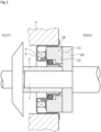
FIG. 1 is a longitudinal sectional view illustrating one example of a mechanical seal as sliding parts according to a first embodiment of the present invention. -
FIG. 2 is a view of a sliding surface of a stationary seal ring in the first embodiment when viewed in an axial direction. -
FIG. 3 is an enlarged view of the sliding surface of the stationary seal ring in the first embodiment when viewed in the axial direction. -
FIG. 4 is a cross-sectional view taken along line A-A ofFIG. 3 . -
FIG. 5 is a view illustrating depth distributions of a first dynamic pressure generation groove and a second dynamic pressure generation groove in the first embodiment in the radial direction. -
FIG. 6 is an enlarged view of the sliding surface of the stationary seal ring in the first embodiment when viewed in the axial direction. -
FIG. 7 is an enlarged view of a sliding surface of a stationary seal ring of sliding parts according to a second embodiment of the present invention when viewed in the axial direction. -
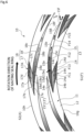
FIG. 8 is an enlarged view of a sliding surface of a stationary seal ring of sliding parts according to a third embodiment of the present invention when viewed in the axial direction. -
FIG. 9 is an enlarged view of a sliding surface of a stationary seal ring of sliding parts according to a fourth embodiment of the present invention when viewed in the axial direction. -
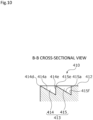
FIG. 10 is a cross-sectional view taken along line B-B ofFIG. 9 . -
FIG. 11 is an enlarged view of a sliding surface of a stationary seal ring of sliding parts according to a fifth embodiment of the present invention when viewed in the axial direction. -
FIG. 12 is an enlarged view of a sliding surface of a stationary seal ring in a first modification example of the embodiments of the present invention when viewed in the axial direction. -
FIG. 13 is an enlarged view of a sliding surface of a stationary seal ring in a second modification example of the embodiments of the present invention when viewed in the axial direction. -
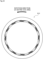
FIG. 14 is a view of a sliding surface of a stationary seal ring in a third modification example of the embodiments of the present invention when viewed in the axial direction. -
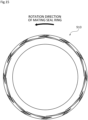
FIG. 15 is a view of a sliding surface of a stationary seal ring in a fourth modification example of the embodiments of the present invention when viewed in the axial direction. - Modes for implementing sliding parts according to the present invention will be described below based on embodiments.
- A mechanical seal as sliding parts according to a first embodiment of the present invention will be described with reference to
FIGS. 1 to 6 . Incidentally, in the present embodiment, a description will be made based on the fact that a sealed fluid F exists in an inner space S1 of the mechanical seal, atmosphere A exists in an outer space S2, a radially inner side of sliding rings forming the mechanical seal is a sealed fluid side (high-pressure side), and a radially outer side is a leakage side (low-pressure side). In addition, for convenience of description, in the drawings, a gradation indicating shallowness and depth may be added to grooves or the like formed on a sliding surface. - A mechanical seal for an automobile illustrated in
FIG. 1 is an outside mechanical seal that seals the sealed fluid F in the inner space S1 which tends to leak from the radially inner side toward the radially outer side of sliding surfaces, and that allows the outer space S2 to communicate with the atmosphere A. Incidentally, in the present embodiment, a mode in which the sealed fluid F is a high-pressure gas and the atmosphere A is a gas having lower pressure than the sealed fluid F will be provided as an example. - The mechanical seal mainly includes a
rotating seal ring 20 as one of a first sliding component and a second sliding component, and astationary seal ring 10 as the other of the first sliding component and the second sliding component. The rotatingseal ring 20 has an annular shape, and is provided on a rotatingshaft 1 so as to be rotatable together with the rotatingshaft 1 via asleeve 2. Thestationary seal ring 10 has an annular shape, and is provided on a seal cover 5 fixed to ahousing 4 of an attached device, so as to be non-rotatable and movable in an axial direction. Thestationary seal ring 10 is biased in the axial direction by an elastic member 7, so that a slidingsurface 11 of thestationary seal ring 10 and a slidingsurface 21 of the rotatingseal ring 20 come into close contact with and slide against each other. Incidentally, the slidingsurface 21 of the rotatingseal ring 20 is a flat surface, and a recessed portion such as a groove is not provided on the flat surface. - The
stationary seal ring 10 and therotating seal ring 20 are typically made of SiC (as an example of hard material) or a combination of SiC and carbon (as an example of soft material); however, the present invention is not limited to these materials, and any sliding material that is used as a sliding material for mechanical seals can be applied. Incidentally, examples of SiC include sintered bodies using boron, aluminum, carbon, or the like as a sintering aid, and materials consisting of two or more phases with different components and compositions, such as SiC in which graphite particles are dispersed, reaction-sintered SiC consisting of SiC and Si, SiC-TiC, and SiC-TiN, and as carbon, mixed carbon of a carbonaceous substance and a graphitic substance, resin-molded carbon, sintered carbon, and the like can be used. In addition, in addition to the above-described sliding materials, metal materials, resin materials, surface modification materials (e.g., coating materials), composite materials, and the like can also be applied. - As illustrated in
FIGS. 2 and3 , therotating seal ring 20 that is a mating seal ring slides counterclockwise relative to thestationary seal ring 10 as indicated by a solid arrow. Hereinafter, this state will be described as relative rotation of thestationary seal ring 10 and therotating seal ring 20 in a forward direction. - A plurality of dynamic
pressure generation mechanisms 13 and a plurality of dynamicpressure generation mechanisms 16 are provided on the radially inner side and the radially outer side of the slidingsurface 11 of thestationary seal ring 10, respectively. The dynamic pressure generation mechanisms 13 (12 in the present embodiment) are evenly arranged in a circumferential direction on the radially inner side of the slidingsurface 11. The dynamic pressure generation mechanisms 16 (12 in the present embodiment) are evenly arranged in the circumferential direction on the radially outer side of the slidingsurface 11. Incidentally, in the present embodiment, the dynamicpressure generation mechanisms pressure generation mechanisms - In addition, portions of the sliding
surface 11 other than the dynamicpressure generation mechanisms lands 12 disposed on the same plane and forming a flat surface. The flat surface of thelands 12 functions as a sliding surface that substantially slides against the slidingsurface 21 of therotating seal ring 20. - As illustrated in
FIG. 3 , each of the dynamicpressure generation mechanisms 13 on the radially inner side includes a first dynamicpressure generation groove 14 and a second dynamicpressure generation groove 15. The first dynamicpressure generation groove 14 communicates with the inner space S1, and extends linearly from an innerperipheral surface 10g of thestationary seal ring 10 in a radially outward direction while being inclined with respect to a relative rotation direction. The second dynamicpressure generation groove 15 extends linearly from a radially outer-side end portion of the first dynamicpressure generation groove 14 in the radially outward direction while being inclined in a direction opposite to the first dynamicpressure generation groove 14 with respect to the relative rotation direction. The groove "being inclined" referred to here indicates that the groove extends in a longitudinal direction in non-parallel to the relative rotation direction (namely, the circumferential direction) and the groove extends non-orthogonal to the relative rotation direction. Incidentally, the location of a part of the groove may be parallel or orthogonal to the relative rotation direction (namely, the circumferential direction). - In addition, the first dynamic
pressure generation groove 14 and the second dynamicpressure generation groove 15 are disposed side by side in the radial direction, and are connected to each other at end portions. - In addition, the second dynamic
pressure generation groove 15 has a longer groove length in a groove extension direction, in other words, a longer groove length in a groove longitudinal direction or a longer groove length in a groove inclination direction, in detail, a longer circumferential component in the groove extension direction than the first dynamicpressure generation groove 14. Incidentally, the first dynamicpressure generation groove 14 and the second dynamicpressure generation groove 15 have a radial component of substantially the same length in the groove extension direction. - In addition, end portions of the second dynamic
pressure generation grooves 15 adjacent to each other are disposed to overlap each other in the radial direction. In detail, an end portion of the second dynamicpressure generation groove 15 on an upstream side of the relative rotation, namely, an end portion including anend edge 15f is disposed on the radially outer side to overlap an end portion of a second dynamic pressure generation groove 15' on a downstream side of the relative rotation, the second dynamic pressure generation groove 15' being adjacent thereto in the circumferential direction, namely, an end portion including anend edge 15e' in the radial direction. - The first dynamic
pressure generation groove 14 includes abottom surface 14a and side surfaces 14b and 14c. Thebottom surface 14a extends linearly while being inclined with respect to the flat surface of thelands 12. The side surfaces 14b and 14c rise from both circumferential end edges of thebottom surface 14a. In addition, anopening 14A communicating with the inner space S1 is formed on a radially inner-side end portion of the first dynamicpressure generation groove 14. - As illustrated in
FIG. 4 , the first dynamicpressure generation groove 14 is inclined in the radial direction with respect to the flat surface of thelands 12 such that anend edge 14d on the radially inner side of thebottom surface 14a located at theopening 14A communicating with the inner space S1 is the deepest and anend edge 14e on the radially outer side of thebottom surface 14a is the shallowest. Namely, the first dynamicpressure generation groove 14 is formed such that the depth becomes shallower from theend edge 14d on the radially inner side toward theend edge 14e on the radially outer side of thebottom surface 14a. In addition, the first dynamicpressure generation groove 14 is formed such that the upstream side of the relative rotation is deep and the downstream side of the relative rotation is shallow for the relative rotation in the forward direction indicated by a solid arrow inFIGS. 2 and3 . - As illustrated in
FIG. 3 , the second dynamicpressure generation groove 15 includes abottom surface 15a, side surfaces 15b and 15c, and a radially inner-side end surface 15d. Thebottom surface 15a extends linearly while being inclined with respect to the flat surface of thelands 12. The side surfaces 15b and 15c rise from both circumferential end edges of thebottom surface 15a. The radially inner-side end surface 15d rises from a radially inner end of thebottom surface 15a, and is orthogonally connected to the side surfaces 15b and 15c. - As illustrated in
FIG. 4 , the second dynamicpressure generation groove 15 is inclined in the radial direction with respect to the flat surface of thelands 12 such that anend edge 15e on the radially inner side of thebottom surface 15a is the deepest and theend edge 15f on the radially outer side of thebottom surface 15a is the shallowest. Namely, the second dynamicpressure generation groove 15 is formed such that the depth becomes shallower from theend edge 15e on the radially inner side toward theend edge 15f on the radially outer side of thebottom surface 15a. In addition, the second dynamicpressure generation groove 15 is formed such that the upstream side of the relative rotation is shallow and the downstream side of the relative rotation is deep for the relative rotation in the forward direction indicated by the solid arrow inFIGS. 2 and3 . - In such a manner, the first dynamic
pressure generation groove 14 and the second dynamicpressure generation groove 15 forming the dynamicpressure generation mechanism 13 are in an opposite depth relationship with respect to the relative rotation direction. - In addition, a depth D1 at the
end edge 14d on the radially inner side of thebottom surface 14a of the first dynamicpressure generation groove 14 is formed to be same as a depth D2 at theend edge 15e on the radially inner side of thebottom surface 15a of the second dynamic pressure generation groove 15 (D1 = D2). In other words, the deepest locations of the first dynamicpressure generation groove 14 and the second dynamicpressure generation groove 15 have the same depth. Incidentally, inFIG. 4 , for convenience of description, the depths D1 and D2 of the first dynamicpressure generation groove 14 and the second dynamicpressure generation groove 15 are represented as deeper than actual ones. In addition, in the present embodiment, theend edge 14e on the radially outer side of thebottom surface 14a of the first dynamicpressure generation groove 14 and theend edge 15f on the radially outer side of thebottom surface 15a of the second dynamicpressure generation groove 15 are disposed on the same plane as the flat surface of thelands 12, and have substantially no depth. - Incidentally, in the present embodiment, in
FIG. 4 , an inclination of thebottom surface 14a of the first dynamicpressure generation groove 14 in the radial direction with respect to the flat surface of thelands 12 is represented as larger than an inclination of thebottom surface 15a of the second dynamicpressure generation groove 15 in the radial direction with respect to the flat surface of thelands 12. The reason is thatFIG. 4 is a cross-sectional view taken along line A-A ofFIG. 3 and, as described above, the second dynamicpressure generation groove 15 is formed with a longer groove length in the groove extension direction, in detail, a longer circumferential component in the groove extension direction than the first dynamicpressure generation groove 14. - In addition, in the present embodiment, as illustrated in
FIG. 5 , the first dynamicpressure generation groove 14 and the second dynamicpressure generation groove 15 are formed such that depth distributions in the radial direction have the same degree of inclination. - As illustrated in
FIG. 3 , the dynamicpressure generation mechanisms 16 on the radially outer side includes a first dynamicpressure generation groove 17 and a second dynamicpressure generation groove 18. The first dynamicpressure generation groove 17 communicates with the outer space S2, and extends linearly from an outerperipheral surface 10h of thestationary seal ring 10 in a radially inward direction while being inclined with respect to the relative rotation direction. The second dynamicpressure generation groove 18 extends linearly from a radially inner-side end portion of the first dynamicpressure generation groove 17 in the radially inward direction while being inclined in a direction opposite to the first dynamicpressure generation groove 17 with respect to the relative rotation direction. - In addition, the first dynamic
pressure generation groove 17 and the second dynamicpressure generation groove 18 are disposed side by side in the radial direction, and are connected to each other at end portions. - In addition, the second dynamic
pressure generation groove 18 has a longer groove length in a groove extension direction, in detail, a longer circumferential component in the groove extension direction than the first dynamicpressure generation groove 17. Incidentally, the first dynamicpressure generation groove 17 and the second dynamicpressure generation groove 18 have a radial component of substantially the same length in the groove extension direction. - In addition, end portions of the second dynamic
pressure generation grooves 18 adjacent to each other are disposed to overlap each other in the radial direction. In detail, an end portion of the second dynamicpressure generation groove 18 on the upstream side of the relative rotation, namely, an end portion including anend edge 18f is disposed on the radially inner side to overlap an end portion of a second dynamic pressure generation groove 18' on the downstream side of the relative rotation, the second dynamic pressure generation groove 18' being adjacent thereto in the circumferential direction, namely, an end portion including anend edge 18e' in the radial direction. - The first dynamic
pressure generation groove 17 includes abottom surface 17a and side surfaces 17b and 17c. Thebottom surface 17a extends linearly while being inclined with respect to the flat surface of thelands 12. The side surfaces 17b and 17c rise from both circumferential end edges of thebottom surface 17a. In addition, anopening 17A communicating with the outer space S2 is formed on a radially outer-side end portion of the first dynamicpressure generation groove 17. - Although not illustrated for convenience of description, the first dynamic
pressure generation groove 17 is inclined in the radial direction with respect to the flat surface of thelands 12 such that anend edge 17d on the radially outer side of thebottom surface 17a located at theopening 17A communicating with the outer space S2 is the deepest and anend edge 17e on the radially inner side of thebottom surface 17a is the shallowest. Namely, the first dynamicpressure generation groove 17 is formed such that the depth becomes shallower from theend edge 17d on the radially outer side toward theend edge 17e on the radially inner side of thebottom surface 17a. In addition, the first dynamicpressure generation groove 17 is formed such that the upstream side of the relative rotation is deep and the downstream side of the relative rotation is shallow for the relative rotation in the forward direction indicated by the solid arrow inFIGS. 2 and3 . - The second dynamic
pressure generation groove 18 includes abottom surface 18a, side surfaces 18b and 18c, and a radially outer-side end surface 18d. Thebottom surface 18a extends linearly while being inclined with respect to the flat surface of thelands 12. The side surfaces 18b and 18c rise from both circumferential end edges of thebottom surface 18a. The radially outer-side end surface 18d rises from a radially inner end of thebottom surface 18a, and is orthogonally connected to the side surfaces 18b and 18c. - Although not illustrated for convenience of description, the second dynamic
pressure generation groove 18 is inclined in the radial direction with respect to the flat surface of thelands 12 such that anend edge 18e on the radially outer side of thebottom surface 18a is the deepest and theend edge 18f on the radially inner side of thebottom surface 18a is the shallowest. Namely, the second dynamicpressure generation groove 18 is formed such that the depth becomes shallower from theend edge 18e on the radially outer side of thebottom surface 18a toward theend edge 18f on the radially inner side of thebottom surface 18a. In addition, the second dynamicpressure generation groove 18 is formed such that the upstream side of the relative rotation is shallow and the downstream side of the relative rotation is deep for the relative rotation in the forward direction indicated by the solid arrow inFIGS. 2 and3 . - In such a manner, the first dynamic
pressure generation groove 17 and the second dynamicpressure generation groove 18 forming the dynamicpressure generation mechanism 16 are in an opposite depth relationship with respect to the relative rotation direction. In addition, the first dynamicpressure generation groove 17 and the second dynamicpressure generation groove 18 are formed such that the dynamicpressure generation mechanism 16 is in a so-called mirror image relationship with respect to the dynamicpressure generation mechanism 13 based on a center line (not illustrated) of the sliding surface in the radial direction. - Next, the operation of the
stationary seal ring 10 and therotating seal ring 20 during relative rotation in the forward direction will be described with reference toFIG. 3 . Incidentally, inFIG. 3 , the flow of the sealed fluid F is indicated by black arrows, and the flow of the atmosphere A is indicated by white arrows. - First, when the
rotating seal ring 20 is not in rotation and is stopped, the sealed fluid F flows into the first dynamicpressure generation groove 14 from theopening 14A, and the sealed fluid F that has flowed into the first dynamicpressure generation groove 14 also flows slightly into the second dynamicpressure generation groove 15 connected to the radially outer side, by crossing over theend edge 14e on the radially outer side of thebottom surface 14a. In addition, the atmosphere A flows into the first dynamicpressure generation groove 17 from theopening 17A, and the atmosphere A that has flowed into the first dynamicpressure generation groove 17 also flows slightly into the second dynamicpressure generation groove 18 connected to the radially inner side, by crossing over theend edge 17e on the radially inner side of thebottom surface 17a. Incidentally, since thestationary seal ring 10 is biased to arotating seal ring 20 side by the elastic member 7, the slidingsurfaces surfaces - As illustrated in
FIG. 3 , when therotating seal ring 20 rotates relative to thestationary seal ring 10 in the forward direction, the sealed fluid F inside the first dynamicpressure generation groove 14 and the second dynamicpressure generation groove 15 follows and moves in the rotation direction of therotating seal ring 20 due to shear with the slidingsurface 21. - Specifically, inside the first dynamic
pressure generation groove 14, as indicated by an arrow F1, the sealed fluid F moves from the vicinity of theopening 14A toward theend edge 14e on the radially outer side. Accordingly, a fluid pressure in the vicinity of theopening 14A becomes relatively lower than a surrounding fluid pressure. In other words, a relative negative pressure is generated in the vicinity of theopening 14A, and as indicated by an arrow F2, the sealed fluid F in the inner space S1 is suctioned into the first dynamicpressure generation groove 14. - In addition, since the depth D1 the
end edge 14d on the radially inner side located at theopening 14A is the deepest in the first dynamic pressure generation groove 14 (refer toFIG. 4 ), a large amount of the sealed fluid F can flow into the first dynamicpressure generation groove 14. - In addition, inside the first dynamic
pressure generation groove 14, as indicated by an arrow F3, the sealed fluid F moves toward theend edge 14e on the radially outer side along theside surface 14b. The sealed fluid F that has moved toward theend edge 14e is increased in pressure at acorner portion 14B formed by theend edge 14e and theside surface 14b and in the vicinity of thecorner portion 14B. Namely, a positive pressure is generated at thecorner portion 14B of the first dynamicpressure generation groove 14 and in the vicinity thereof. - In addition, since the depth of the first dynamic
pressure generation groove 14 becomes shallower from theend edge 14d on the radially inner side toward theend edge 14e on the radially outer side, the sealed fluid F is easily increased in pressure even in the process of moving toward thecorner portion 14B of the first dynamicpressure generation groove 14. In addition, even when the movement amount of the sealed fluid F is small due to a low rotation speed of therotating seal ring 20, a positive pressure is likely to be generated at thecorner portion 14B of the first dynamicpressure generation groove 14 and in the vicinity thereof. - In addition, the sliding
surfaces corner portion 14B of the first dynamicpressure generation groove 14 and in the vicinity thereof (not illustrated). Accordingly, as indicated by an arrow F4, the sealed fluid F inside the first dynamicpressure generation groove 14 mainly flows into a gap between the slidingsurfaces surfaces surfaces surfaces pressure generation groove 14 into the gap between the slidingsurfaces surfaces pressure generation groove 15 of the dynamicpressure generation mechanism 13 adjacent in the circumferential direction (refer to an arrow F6), there is almost no leakage to the outer space S2. - In addition, inside the second dynamic
pressure generation groove 15, as indicated by an arrow F5, the sealed fluid F moves from theend edge 15f on the radially outer side toward theend edge 15e on the radially inner side. Since the depth of the second dynamicpressure generation groove 15 becomes deeper from theend edge 15f on the radially outer side toward theend edge 15e on the radially inner side, almost no dynamic pressure is generated inside the second dynamicpressure generation groove 15. - In detail, a relative negative pressure is generated in the vicinity of the
end edge 15f on the radially outer side of the second dynamicpressure generation groove 15, and a relative positive pressure is generated in the vicinity of theend edge 15e on the radially inner side, but the absolute values of the negative pressure and the positive pressure are very small. For this reason, as described above, a dynamic pressure is much less likely to be generated in the second dynamicpressure generation groove 15 than in the first dynamicpressure generation groove 14. - In addition, as indicated by the arrow F6, the sealed fluid F that has flowed out from a first dynamic pressure generation groove 14' of the dynamic pressure generation mechanism 13', which is adjacent on the upstream side of the relative rotation in the circumferential direction, into the gap between the sliding
surfaces pressure generation groove 15. Further, a fraction of the sealed fluid F that has crossed over theend edge 14e of the first dynamicpressure generation groove 14 of the same dynamicpressure generation mechanism 13 flows into the second dynamicpressure generation groove 15. For this reason as well, a dynamic pressure is less likely to be generated in the second dynamicpressure generation groove 15. - Further, as illustrated in
FIG. 5 , the bottom surfaces 14a and 15a of the first dynamicpressure generation groove 14 and the second dynamicpressure generation groove 15 are inclined such that the depth distributions in the radial direction have the same linear degree of inclination, so that a positive pressure is more likely to be generated in the first dynamicpressure generation groove 14, and a negative pressure is less likely to be generated in the second dynamicpressure generation groove 15. Incidentally, these inclinations may be curved rather than linear. In addition, the inclination of the first dynamicpressure generation groove 14 and the inclination of the second dynamicpressure generation groove 15 may not be the same degree of inclination in depth distribution in the radial direction. - Incidentally, since the flow of the atmosphere A in the dynamic
pressure generation mechanism 16 can be described as substantially the same flow as the sealed fluid F in the dynamicpressure generation mechanism 13 described above (refer to the white arrows illustrated inFIG. 3 ), the detailed description will be omitted. - Next, the operation of the
stationary seal ring 10 and therotating seal ring 20 during relative rotation in a reverse direction will be described with reference toFIG. 6 . Incidentally, similarly toFIG. 3 , inFIG. 6 as well, the flow of the sealed fluid F is indicated by black arrows, and the flow of the atmosphere A is indicated by white arrows. In addition, since a mode when therotating seal ring 20 is stopped is the same, the description will be omitted. - As illustrated in
FIG. 6 , when therotating seal ring 20 rotates relative to thestationary seal ring 10 in the reverse direction, the sealed fluid F inside the first dynamicpressure generation groove 14 and the second dynamicpressure generation groove 15 follows and moves in the rotation direction of therotating seal ring 20 due to shear with the slidingsurface 21. - Specifically, inside the first dynamic
pressure generation groove 14, as indicated by an arrow F11, the sealed fluid F moves from theend edge 14e on the radially outer side toward theopening 14A. Since the depth of the first dynamicpressure generation groove 14 becomes deeper from theend edge 14e on the radially outer side toward theend edge 14d on the radially inner side, almost no dynamic pressure is generated inside the first dynamicpressure generation groove 14. - In detail, a relative negative pressure is generated in the vicinity of the
end edge 14e on the radially outer side of the first dynamicpressure generation groove 14, and a relative positive pressure is generated in the vicinity of theend edge 14d on the radially inner side, but the absolute values of the negative pressure and the positive pressure are very small. For this reason, as described above, a dynamic pressure is much less likely to be generated in the first dynamicpressure generation groove 14 than in the second dynamicpressure generation groove 15. - In addition, since the first dynamic
pressure generation groove 14 communicates with the inner space S1 through theopening 14A, almost no dynamic pressure is generated inside the first dynamicpressure generation groove 14. For this reason, almost no sealed fluid F is suctioned from between the slidingsurfaces pressure generation groove 14. - In addition, inside the second dynamic
pressure generation groove 15, as indicated by an arrow F12, the sealed fluid F moves from theend edge 15e on the radially inner side toward theend edge 15f on the radially outer side. Accordingly, a fluid pressure at theend edge 15e on the radially inner side becomes relatively lower than a surrounding fluid pressure. In other words, a relative negative pressure is generated in the vicinity of theend edge 15e on the radially inner side, and as indicated by an arrow F13, the sealed fluid F that has flowed out from the second dynamic pressure generation groove 15' of the dynamic pressure generation mechanism 13', which is adjacent on the upstream side of the relative rotation in the circumferential direction, into the gap between the slidingsurfaces pressure generation groove 15. Incidentally, as described above, since almost no dynamic pressure is generated in the first dynamicpressure generation groove 14, a fluid pressure at theend edge 15e on the radially inner side of the second dynamicpressure generation groove 15 becomes relatively lower than the fluid pressure at theend edge 14e on the radially outer side of the first dynamicpressure generation groove 14. For this reason, the sealed fluid F between the slidingsurfaces pressure generation groove 15 than into the first dynamicpressure generation groove 14. - In addition, since the depth D2 of the
end edge 15e on the radially inner side is the deepest in the second dynamic pressure generation groove 15 (refer toFIG. 4 ), a large amount of the sealed fluid F can flow into the second dynamicpressure generation groove 15. - In addition, inside the second dynamic
pressure generation groove 15, as indicated by an arrow F14, the sealed fluid F moves toward theend edge 15f on the radially outer side along theside surface 15b. The sealed fluid F that has moved toward theend edge 15f is increased in pressure at acorner portion 15B formed by theend edge 15f and theside surface 15b and in the vicinity of thecorner portion 15B. Namely, a positive pressure is generated at thecorner portion 15B of the second dynamicpressure generation groove 15 and in the vicinity thereof. - In addition, since the depth of the second dynamic
pressure generation groove 15 becomes shallower from theend edge 15e on the radially inner side toward theend edge 15f on the radially outer side, the sealed fluid F is easily increased in pressure even in the process of moving toward thecorner portion 15B of the second dynamicpressure generation groove 15. In addition, even when the movement amount of the sealed fluid F is small due to a low rotation speed of therotating seal ring 20, a positive pressure is likely to be generated at thecorner portion 15B of the second dynamicpressure generation groove 15 and in the vicinity thereof. - Further, since the second dynamic
pressure generation groove 15 is formed longer in the extension direction, in detail, with a longer circumferential component in the groove extension direction than the first dynamicpressure generation groove 14, the sealed fluid F is further increased in pressure in the process of moving toward thecorner portion 15B of the second dynamicpressure generation groove 15. - In addition, the sliding
surfaces corner portion 15B of the second dynamicpressure generation groove 15 and in the vicinity thereof (not illustrated). Accordingly, as indicated by an arrow F15, the sealed fluid F inside the second dynamicpressure generation groove 15 mainly flows into the gap between the slidingsurfaces end edge 15f on the radially outer side of the second dynamicpressure generation groove 15 is disposed on the same plane as the flat surface of thelands 12, a positive pressure is generated not only at thecorner portion 15B but also in a wide range over theend edge 15f on the radially outer side. Since the sealed fluid F is interposed between the slidingsurfaces surfaces - Incidentally, since the flow of the atmosphere A in the dynamic
pressure generation mechanism 16 can be described as substantially the same flow as the sealed fluid F in the dynamicpressure generation mechanism 13 described above (refer to the white arrows illustrated inFIG. 6 ), the detailed description will be omitted. - Incidentally, in the present embodiment, during relative rotation in the forward direction illustrated in
FIG. 3 and during relative rotation in the reverse direction illustrated inFIG. 6 , positive pressures of the same degree are generated in the entirety of the dynamicpressure generation mechanisms - As described above, in the first dynamic
pressure generation grooves pressure generation grooves pressure generation mechanisms FIG. 3 ), the first dynamicpressure generation grooves pressure generation grooves pressure generation grooves pressure generation grooves FIG. 6 ), a negative pressure is less likely to be generated in the first dynamicpressure generation grooves pressure generation grooves surface 11, to separate the slidingsurfaces stationary seal ring 10 and therotating seal ring 20 have excellent lubricity. - In addition, in the first dynamic
pressure generation groove 14 forming the dynamicpressure generation mechanism 13, the end portion on a deep side, namely, the end portion including theend edge 14d communicates with the inner space S1 that is a space on a sealed fluid F side as a sealed fluid side space, and in the first dynamicpressure generation groove 17 forming the dynamicpressure generation mechanism 16, the end portion on a deep side, namely, the end portion including theend edge 17d communicates with the outer space S2 that is a space on an atmosphere A side as a leakage side space. According to this configuration, for the relative rotation in the forward direction, since the sealed fluid F or the atmosphere A is easily supplied into the first dynamicpressure generation grooves pressure generation grooves - In addition, the second dynamic
pressure generation grooves pressure generation grooves pressure generation grooves pressure generation grooves pressure generation grooves - In addition, since the first dynamic
pressure generation grooves pressure generation grooves lands 12 interposed therebetween, the supply of the fluid between the first dynamicpressure generation grooves pressure generation grooves - In addition, the first dynamic
pressure generation grooves pressure generation grooves surface 11, the dynamic pressures are likely to be evenly generated in the circumferential direction of the slidingsurface 11. In addition, the dynamicpressure generation mechanisms surface 11. - In addition, the sliding
surface 21 of therotating seal ring 20 is a flat surface, and the first dynamicpressure generation grooves pressure generation grooves surface 11 of thestationary seal ring 10. According to this configuration, the balance of the dynamic pressures generated in the entirety of the first dynamicpressure generation grooves pressure generation grooves - In addition, since the first dynamic
pressure generation grooves pressure generation grooves FIG. 4 ), for the relative rotations in both directions, the balances of the dynamic pressures generated in the entirety of the first dynamicpressure generation grooves pressure generation grooves - Next, sliding parts according to a second embodiment of the present invention will be described with reference to
FIG. 7 . Incidentally, the descriptions of configurations that are the same as and overlap with the configurations of the first embodiment will be omitted. - As illustrated in
FIG. 7 , astationary seal ring 210 of the second embodiment is different from that of the first embodiment in that a first dynamicpressure generation groove 214 and a second dynamicpressure generation groove 215 forming a dynamicpressure generation mechanism 213 and a first dynamicpressure generation groove 217 and a second dynamicpressure generation groove 218 forming a dynamicpressure generation mechanism 216 are each separated and are not connected to each other in the radial direction, and has the same configuration as that of the first embodiment in other aspects. - In the
stationary seal ring 210 of the second embodiment, the first dynamicpressure generation grooves pressure generation grooves end edge 214e on the radially outer side of abottom surface 214a of the first dynamicpressure generation groove 214 and anend edge 215e on the radially inner side of abottom surface 215a of the second dynamicpressure generation groove 215 are separated from each other substantially in parallel to each other, anend edge 217e on the radially inner side of abottom surface 217a of the first dynamicpressure generation groove 217 and anend edge 218e on the radially outer side of abottom surface 218a of the second dynamicpressure generation groove 218 are separated from each other substantially in parallel to each other, and a portion therebetween is aland 212a having a belt shape and extending in the circumferential direction. Incidentally, theland 212a having a belt shape is a part of aland 212. - In the
stationary seal ring 210 of the second embodiment, compared to the mode of the first embodiment, since the sealed fluid F or the atmosphere A can flow into a gap between slidingsurface end edge 214e on the radially outer side of the first dynamicpressure generation groove 214 and theend edge 217e on the radially inner side of the first dynamicpressure generation groove 217, a positive pressure can be generated in a wider range. - Next, sliding parts according to a third embodiment of the present invention will be described with reference to
FIG. 8 . Incidentally, the descriptions of configurations that are the same as and overlap with the configurations of the first embodiment will be omitted. - As illustrated in
FIG. 8 , astationary seal ring 310 of the third embodiment is different from that of the first embodiment in that a second dynamicpressure generation groove 315 forming a dynamicpressure generation mechanism 313 and a second dynamicpressure generation groove 318 forming a dynamicpressure generation mechanism 316 have longer radial components in extension directions and have circumferential components of substantially the same lengths in the groove extension directions as first dynamicpressure generation grooves - In addition, although not illustrated for convenience of description, in the third embodiment, unlike the first embodiment, the second dynamic
pressure generation grooves pressure generation grooves - In the
stationary seal ring 310 of the third embodiment, since the second dynamicpressure generation grooves pressure generation grooves pressure generation mechanisms surface 311 in a well-balanced manner. - Next, sliding parts according to a fourth embodiment of the present invention will be described with reference to
FIGS. 9 and10 . Incidentally, the descriptions of configurations that are the same as and overlap with the configurations of the first and third embodiments will be omitted. - As illustrated in
FIG. 9 , astationary seal ring 410 of the fourth embodiment is formed such that in a first dynamicpressure generation groove 414 and a second dynamicpressure generation groove 415 forming a dynamicpressure generation mechanism 413 and in a first dynamicpressure generation groove 417 and a second dynamicpressure generation groove 418 forming a dynamicpressure generation mechanism 416, radial components and circumferential components in groove extension directions are formed with substantially the same respective lengths. - As illustrated in
FIG. 10 , the first dynamicpressure generation groove 414 is inclined in the radial direction with respect to the flat surface of thelands 12 such that anend edge 414d on the radially inner side of abottom surface 414a is the shallowest and anend edge 414e on the radially outer side of thebottom surface 414a is the deepest. Namely, the first dynamicpressure generation groove 414 is formed such that the depth becomes deeper from theend edge 414d on the radially inner side toward theend edge 414e on the radially outer side of thebottom surface 414a. In addition, the first dynamicpressure generation groove 414 is formed such that for relative rotation in the forward direction indicated by a solid arrow inFIG. 9 , an upstream side of the relative rotation is shallow and a downstream side of the relative rotation is deep. - The second dynamic
pressure generation groove 415 is inclined in the radial direction such that anend edge 415e on the radially inner side of abottom surface 415a is the shallowest and anend edge 415f on the radially outer side of thebottom surface 415a is the deepest. Namely, the second dynamicpressure generation groove 415 is formed such that the depth becomes deeper from theend edge 415e on the radially inner side toward theend edge 415f on the radially outer side of thebottom surface 415a. In addition, the second dynamicpressure generation groove 415 is formed such that for the relative rotation in the forward direction indicated by the solid arrow inFIG. 9 , the upstream side of the relative rotation is deep and the downstream side of the relative rotation is shallow. - In addition, although not illustrated for convenience of description, in the fourth embodiment, the first dynamic
pressure generation grooves pressure generation grooves - In such a manner, the first dynamic
pressure generation groove 414 and the second dynamicpressure generation groove 415 forming the dynamicpressure generation mechanism 413 are in an opposite depth relationship with respect to the relative rotation direction. In addition, although the detailed description is omitted, the first dynamicpressure generation groove 417 and the second dynamicpressure generation groove 418 are formed such that the dynamicpressure generation mechanism 416 is in a so-called mirror image relationship with respect to the dynamicpressure generation mechanism 413 based on a center line (not illustrated) of the sliding surface in the radial direction. - In the
stationary seal ring 410 of the fourth embodiment, the first dynamicpressure generation grooves pressure generation groove 414 and the second dynamicpressure generation groove 415 forming the dynamicpressure generation mechanism 413 and the first dynamicpressure generation groove 417 and the second dynamicpressure generation groove 418 forming the dynamicpressure generation mechanism 416 are formed with the radial components and the circumferential components of substantially the same respective lengths in the groove extension directions, so that positive pressures of the same degree can be generated for the relative rotations in both directions. - Next, sliding parts according to a fifth embodiment of the present invention will be described with reference to
FIG. 11 . Incidentally, the descriptions of configurations that are the same as and overlap with the configurations of the second embodiment will be omitted. - As illustrated in
FIG. 11 , astationary seal ring 510 of the fifth embodiment is different from those of the first and second embodiments in that a first dynamicpressure generation groove 514 forming a dynamicpressure generation mechanism 513 and a first dynamicpressure generation groove 517 forming a dynamicpressure generation mechanism 516 do not each communicate with the inner space S1 or the outer space S2, and are formed with longer circumferential components in groove extension directions than second dynamicpressure generation grooves pressure generation grooves pressure generation groove 514 and one first dynamicpressure generation groove 517, respectively, and in that the first dynamicpressure generation grooves pressure generation grooves - In the
stationary seal ring 510 of the fifth embodiment, since the first dynamicpressure generation grooves pressure generation grooves pressure generation groove 514 and the first dynamicpressure generation groove 517, respectively, which are formed with long circumferential components in the groove extension directions and with large groove widths, so that positive pressures of the same degree can be generated for the relative rotations in both directions. - The embodiments of the present invention have been described above with reference to the drawings; however, the specific configurations are not limited to the embodiments, and modifications or additions that are made without departing from the scope of the present invention are included in the present invention.
- For example, in the embodiments, the mechanical seals for automobiles have been described as examples of the sliding parts; however, the sliding parts may be other mechanical seals for general industrial machines or the like.
- In addition, in the first to fifth embodiments, an example in which the first dynamic pressure generation grooves and the second dynamic pressure generation grooves forming the dynamic pressure generation mechanism are provided in the stationary seal ring has been described; however, the first dynamic pressure generation grooves and the second dynamic pressure generation grooves may be provided in the rotating seal ring, or one first dynamic pressure generation groove and one second dynamic pressure generation groove or both may be provided in the stationary seal ring and the rotating seal ring. In other words, the first sliding component and the second sliding component of the sliding parts according to the present invention may be the stationary seal ring and the rotating seal ring, respectively, or may be the rotational seal ring and the stationary seal ring, respectively.
- In addition, in the first to fifth embodiments, the sealed fluid side and the leakage side have been described as a high-pressure side and a low-pressure side, respectively; however, the sealed fluid side and the leakage side may have substantially the same pressure.
- In addition, in the first to fifth embodiments, the radially inner side and the radially outer side have been described as the sealed fluid side and the leakage side, respectively; however, the radially outer side and the radially inner side may be the sealed fluid side and the leakage side, respectively.
- In addition, in the first to fifth embodiments, the sealed fluid F has been described as a high-pressure gas, but is not limited thereto, and may be a liquid or a low-pressure gas or may be in the form of a mist that is a mixture of liquid and gas.
- In addition, in the first to fifth embodiments, the fluid on the leakage side has been described as the atmosphere A that is a low-pressure gas, but is not limited thereto, and may be a liquid or a high-pressure gas or may be in the form of a mist that is a mixture of liquid and gas.
- In addition, in the first to fifth embodiments, a mode in which the first dynamic pressure generation grooves and the second dynamic pressure generation grooves extend linearly has been provided as an example; however, the first dynamic pressure generation grooves and the second dynamic pressure generation grooves may extend in a curved manner. Namely, when the grooves are viewed in the axial direction, the grooves may have a structure in which the grooves are narrowed on at least one side in the circumferential direction of the grooves.
- In addition, in the first to fifth embodiments, a mode in which the bottom surfaces of the first dynamic pressure generation groove and the second dynamic pressure generation groove extend linearly while being inclined with respect to the flat surface of the lands has been provided as an example; however, the bottom surfaces of the first dynamic pressure generation groove and the second dynamic pressure generation groove may be curved or changed in a stepwise manner as long as the depths of the bottom surfaces become deeper or shallower in the groove extension directions.
- In addition, in the first to fifth embodiments, a mode in which the shallowest end edges of the bottom surfaces of the first dynamic pressure generation groove and the second dynamic pressure generation groove are disposed on the same plane as the flat surface of the lands has been provided as an example; however, the shallowest end edges of the bottom surfaces of the first dynamic pressure generation groove and the second dynamic pressure generation groove may have a predetermined depth as long as the depth enables positive pressures to be sufficiently generated.
- In addition, in the first to fifth embodiments, as in a
stationary seal ring 610 of a first modification example illustrated inFIG. 12 , the first dynamic pressure generation grooves and the second dynamic pressure generation grooves may be displaced to be offset from each other in the circumferential direction. Incidentally, end portions may be partially connected in a state where the first dynamic pressure generation grooves and the second dynamic pressure generation grooves are offset from each other in the circumferential direction. - In addition, in the first to fifth embodiments, as in a
stationary seal ring 710 of a second modification example illustrated inFIG. 13 , the inclinations of the first dynamic pressure generation groove and the second dynamic pressure generation groove with respect to the relative rotation direction (circumferential direction) may be formed in opposite directions. - In addition, in the first to fifth embodiments and the first and second modification examples, a mode in which the dynamic pressure generation mechanisms are formed on the radially inner side and the radially outer side of the sliding surface has been provided as an example; however, as in a
stationary seal ring 810 of a third modification example illustrated inFIG. 14 , the dynamic pressure generation mechanisms may be provided only on the radially inner side of the sliding surface, or as in astationary seal ring 910 of a fourth modification example illustrated inFIG. 15 , the dynamic pressure generation mechanisms may be formed only on the radially outer side of the sliding surface. In addition, three or more dynamic pressure generation mechanisms may be formed in the radial direction of the sliding surface. - In addition, in the first to fifth embodiments and the first to fourth modification examples, a mode in which the first dynamic pressure generation groove and the second dynamic pressure generation groove are disposed side by side in the radial direction has been provided as an example; however, the first dynamic pressure generation groove and the second dynamic pressure generation groove may be disposed side by side in the circumferential direction.
-
- 1
- Rotating shaft
- 2
- Sleeve
- 4
- Housing
- 10
- Stationary seal ring (sliding component)
- 11
- Sliding surface
- 12
- Land
- 13, 16
- Dynamic pressure generation mechanism
- 14
- First dynamic pressure generation groove
- 15
- Second dynamic pressure generation groove
- 17
- First dynamic pressure generation groove
- 18
- Second dynamic pressure generation groove
- 20
- Rotating seal ring (sliding component)
- 21
- Sliding surface
- A
- Atmosphere
- F
- Sealed fluid
- S1
- Inner space (sealed fluid side space)
- S2
- Outer space (leakage side space)
Claims (6)
- Sliding parts which are disposed at a relative rotational location of a rotating machine, comprising a first sliding component having a first sliding surface and a second sliding component having a second sliding surface relatively slidable with the first sliding surface, the first sliding surface or the second sliding surface being provided with a first dynamic pressure generation groove extending so as to be inclined with respect to a relative rotation direction in a plan view, the first sliding surface or the second sliding surface being provided with a second dynamic pressure generation groove extending so as to be inclined in a direction opposite to an inclination direction of the first dynamic pressure generation groove with respect to the relative rotation direction in the plan view,
wherein a bottom surface of the first dynamic pressure generation groove is equal, in inclination direction with respect to a radial direction, to a bottom surface of the second dynamic pressure generation groove in a cross-sectional view. - The sliding parts according to claim 1,
wherein an end portion on a deep side of the first dynamic pressure generation groove communicates with a sealed fluid side space or a leakage side space. - The sliding parts according to claim 2,
wherein the second dynamic pressure generation groove is a closed groove, and a length of the second dynamic pressure generation groove in an inclination direction of the second dynamic pressure generation groove is longer than a length of the first dynamic pressure generation groove in an inclination direction of the first dynamic pressure generation groove. - The sliding parts according to any one of claims 1 to 3,
wherein the first dynamic pressure generation groove and the second dynamic pressure generation groove communicate with each other. - The sliding parts according to any one of claims 1 to 3,
wherein the first dynamic pressure generation groove and the second dynamic pressure generation groove are disposed side by side in the radial direction. - The sliding parts according to claim 1,
wherein both the first dynamic pressure generation groove and the second dynamic pressure generation groove are provided on one of the first sliding surface and the second sliding surface.
Applications Claiming Priority (2)
| Application Number | Priority Date | Filing Date | Title |
|---|---|---|---|
| JP2021138020 | 2021-08-26 | ||
| PCT/JP2022/031862 WO2023027102A1 (en) | 2021-08-26 | 2022-08-24 | Sliding component |
Publications (2)
| Publication Number | Publication Date |
|---|---|
| EP4394217A1 true EP4394217A1 (en) | 2024-07-03 |
| EP4394217A4 EP4394217A4 (en) | 2025-08-27 |
Family
ID=85322789
Family Applications (1)
| Application Number | Title | Priority Date | Filing Date |
|---|---|---|---|
| EP22861390.7A Pending EP4394217A4 (en) | 2021-08-26 | 2022-08-24 | SLIDING COMPONENT |
Country Status (6)
| Country | Link |
|---|---|
| US (1) | US20240344555A1 (en) |
| EP (1) | EP4394217A4 (en) |
| JP (1) | JP7842769B2 (en) |
| KR (1) | KR20240046244A (en) |
| CN (1) | CN117836546A (en) |
| WO (1) | WO2023027102A1 (en) |
Families Citing this family (3)
| Publication number | Priority date | Publication date | Assignee | Title |
|---|---|---|---|---|
| US12404936B2 (en) * | 2021-09-28 | 2025-09-02 | Eagle Indusry Co., Ltd. | Sliding component |
| CN117469302A (en) * | 2023-10-20 | 2024-01-30 | 昆明理工大学 | A surface mesh texture structure based on water-lubricated silicon carbide bearings |
| WO2026088835A1 (en) * | 2024-10-24 | 2026-04-30 | イーグル工業株式会社 | Sliding component |
Family Cites Families (20)
| Publication number | Priority date | Publication date | Assignee | Title |
|---|---|---|---|---|
| US3380040A (en) * | 1964-04-01 | 1968-04-23 | Hughes Aircraft Co | Hydrodynamic bearing support for a magnetic drum |
| US3855624A (en) * | 1973-08-15 | 1974-12-17 | Philips Corp | Grooved air bearing head |
| US5201531A (en) * | 1992-04-02 | 1993-04-13 | John Crane Inc. | Face seal with double spiral grooves |
| JPH08296745A (en) * | 1995-04-26 | 1996-11-12 | Mitsubishi Heavy Ind Ltd | Mechanical seal |
| US6152452A (en) * | 1997-10-17 | 2000-11-28 | Wang; Yuming | Face seal with spiral grooves |
| US7044470B2 (en) * | 2000-07-12 | 2006-05-16 | Perkinelmer, Inc. | Rotary face seal assembly |
| JP4719414B2 (en) | 2003-12-22 | 2011-07-06 | イーグル工業株式会社 | Sliding parts |
| EP2549155B1 (en) * | 2010-03-15 | 2016-08-10 | Eagle Industry Co., Ltd. | Sliding member |
| US9039013B2 (en) * | 2011-05-04 | 2015-05-26 | United Technologies Corporation | Hydrodynamic non-contacting seal |
| CN103732958B (en) * | 2011-09-10 | 2016-09-21 | 伊格尔工业股份有限公司 | Slide unit |
| US9353865B2 (en) * | 2014-06-03 | 2016-05-31 | Thermo King Corporation | Mechanical face seal |
| EP3929455B1 (en) * | 2014-12-22 | 2026-01-28 | Eagle Industry Co., Ltd. | Plain bearing and pump |
| US10494941B2 (en) * | 2016-10-17 | 2019-12-03 | United Technologies Corporation | Seal face plate cooling |
| JP7224740B2 (en) * | 2018-08-08 | 2023-02-20 | イーグル工業株式会社 | mechanical seal |
| KR102541901B1 (en) | 2018-12-21 | 2023-06-13 | 이구루코교 가부시기가이샤 | sliding parts |
| WO2020209258A1 (en) * | 2019-04-09 | 2020-10-15 | イーグル工業株式会社 | Sliding component |
| CN210800068U (en) | 2019-05-21 | 2020-06-19 | 昆明理工大学 | A double-layer spiral groove dry gas sealing ring |
| DE102020203764A1 (en) * | 2020-03-24 | 2021-09-30 | Eagleburgmann Germany Gmbh & Co. Kg | Mechanical seal with improved groove arrangement |
| CN111306302B (en) * | 2020-04-02 | 2025-04-29 | 清华大学 | Mechanical seal end face structure and rotating mechanical equipment capable of reducing end face wear |
| CN213899890U (en) | 2020-12-01 | 2021-08-06 | 四川久龙密封件制造有限公司 | Dry gas sealing device |
-
2022
- 2022-08-24 KR KR1020247008518A patent/KR20240046244A/en active Pending
- 2022-08-24 WO PCT/JP2022/031862 patent/WO2023027102A1/en not_active Ceased
- 2022-08-24 US US18/685,161 patent/US20240344555A1/en active Pending
- 2022-08-24 EP EP22861390.7A patent/EP4394217A4/en active Pending
- 2022-08-24 JP JP2023543950A patent/JP7842769B2/en active Active
- 2022-08-24 CN CN202280057538.9A patent/CN117836546A/en active Pending
Also Published As
| Publication number | Publication date |
|---|---|
| CN117836546A (en) | 2024-04-05 |
| WO2023027102A1 (en) | 2023-03-02 |
| JPWO2023027102A1 (en) | 2023-03-02 |
| US20240344555A1 (en) | 2024-10-17 |
| KR20240046244A (en) | 2024-04-08 |
| JP7842769B2 (en) | 2026-04-08 |
| EP4394217A4 (en) | 2025-08-27 |
Similar Documents
| Publication | Publication Date | Title |
|---|---|---|
| US11821461B2 (en) | Sliding components | |
| US12467538B2 (en) | Sliding component | |
| US11603934B2 (en) | Sliding component | |
| US11767916B2 (en) | Sliding components | |
| EP2881633B1 (en) | Sliding component | |
| US20240344555A1 (en) | Sliding parts | |
| EP3929454B1 (en) | Sliding components | |
| US20260085755A1 (en) | Sliding components | |
| US20250354608A1 (en) | Sliding component | |
| WO2021215224A1 (en) | Pair of sliding components | |
| US12404936B2 (en) | Sliding component | |
| EP4372253A1 (en) | Sliding components | |
| US20250003495A1 (en) | Sliding element | |
| US20250137484A1 (en) | Sliding component | |
| US20240344561A1 (en) | Sliding component | |
| US20250327480A1 (en) | Sliding component | |
| EP4644732A1 (en) | Sliding component | |
| EP4644733A1 (en) | Sliding components | |
| CN115210488B (en) | Sliding member | |
| EP4130523A1 (en) | Sliding component | |
| WO2025239228A1 (en) | Sliding component |
Legal Events
| Date | Code | Title | Description |
|---|---|---|---|
| STAA | Information on the status of an ep patent application or granted ep patent |
Free format text: STATUS: THE INTERNATIONAL PUBLICATION HAS BEEN MADE |
|
| PUAI | Public reference made under article 153(3) epc to a published international application that has entered the european phase |
Free format text: ORIGINAL CODE: 0009012 |
|
| STAA | Information on the status of an ep patent application or granted ep patent |
Free format text: STATUS: REQUEST FOR EXAMINATION WAS MADE |
|
| 17P | Request for examination filed |
Effective date: 20240220 |
|
| AK | Designated contracting states |
Kind code of ref document: A1 Designated state(s): AL AT BE BG CH CY CZ DE DK EE ES FI FR GB GR HR HU IE IS IT LI LT LU LV MC MK MT NL NO PL PT RO RS SE SI SK SM TR |
|
| DAV | Request for validation of the european patent (deleted) | ||
| DAX | Request for extension of the european patent (deleted) | ||
| A4 | Supplementary search report drawn up and despatched |
Effective date: 20250728 |
|
| RIC1 | Information provided on ipc code assigned before grant |
Ipc: F16J 15/34 20060101AFI20250722BHEP Ipc: F16C 33/10 20060101ALI20250722BHEP Ipc: F16C 17/04 20060101ALI20250722BHEP |