KR20240046244A - sliding parts - Google Patents
sliding parts Download PDFInfo
- Publication number
- KR20240046244A KR20240046244A KR1020247008518A KR20247008518A KR20240046244A KR 20240046244 A KR20240046244 A KR 20240046244A KR 1020247008518 A KR1020247008518 A KR 1020247008518A KR 20247008518 A KR20247008518 A KR 20247008518A KR 20240046244 A KR20240046244 A KR 20240046244A
- Authority
- KR
- South Korea
- Prior art keywords
- dynamic pressure
- groove
- pressure generation
- generation groove
- relative rotation
- Prior art date
Links
- 239000012530 fluid Substances 0.000 claims description 77
- 230000004044 response Effects 0.000 abstract description 3
- 230000007246 mechanism Effects 0.000 description 45
- 238000007789 sealing Methods 0.000 description 44
- 230000003068 static effect Effects 0.000 description 39
- 230000004048 modification Effects 0.000 description 11
- 238000012986 modification Methods 0.000 description 11
- 238000011144 upstream manufacturing Methods 0.000 description 10
- 239000000463 material Substances 0.000 description 9
- OKTJSMMVPCPJKN-UHFFFAOYSA-N Carbon Chemical compound [C] OKTJSMMVPCPJKN-UHFFFAOYSA-N 0.000 description 8
- 239000007787 solid Substances 0.000 description 7
- 229910052799 carbon Inorganic materials 0.000 description 6
- 239000007788 liquid Substances 0.000 description 4
- 238000004891 communication Methods 0.000 description 3
- 238000000034 method Methods 0.000 description 3
- 230000008569 process Effects 0.000 description 3
- 229910002804 graphite Inorganic materials 0.000 description 2
- 239000010439 graphite Substances 0.000 description 2
- 238000005461 lubrication Methods 0.000 description 2
- 239000003595 mist Substances 0.000 description 2
- 239000000203 mixture Substances 0.000 description 2
- 230000002093 peripheral effect Effects 0.000 description 2
- 239000011347 resin Substances 0.000 description 2
- 229920005989 resin Polymers 0.000 description 2
- 238000010008 shearing Methods 0.000 description 2
- ZOXJGFHDIHLPTG-UHFFFAOYSA-N Boron Chemical compound [B] ZOXJGFHDIHLPTG-UHFFFAOYSA-N 0.000 description 1
- 238000007792 addition Methods 0.000 description 1
- 229910052782 aluminium Inorganic materials 0.000 description 1
- XAGFODPZIPBFFR-UHFFFAOYSA-N aluminium Chemical compound [Al] XAGFODPZIPBFFR-UHFFFAOYSA-N 0.000 description 1
- 229910052796 boron Inorganic materials 0.000 description 1
- 239000011248 coating agent Substances 0.000 description 1
- 238000000576 coating method Methods 0.000 description 1
- 239000002131 composite material Substances 0.000 description 1
- 238000010586 diagram Methods 0.000 description 1
- 230000007613 environmental effect Effects 0.000 description 1
- 239000007769 metal material Substances 0.000 description 1
- 239000002245 particle Substances 0.000 description 1
- 238000005245 sintering Methods 0.000 description 1
- 239000007779 soft material Substances 0.000 description 1
Images


Classifications
-
- F—MECHANICAL ENGINEERING; LIGHTING; HEATING; WEAPONS; BLASTING
- F16—ENGINEERING ELEMENTS AND UNITS; GENERAL MEASURES FOR PRODUCING AND MAINTAINING EFFECTIVE FUNCTIONING OF MACHINES OR INSTALLATIONS; THERMAL INSULATION IN GENERAL
- F16J—PISTONS; CYLINDERS; SEALINGS
- F16J15/00—Sealings
- F16J15/16—Sealings between relatively-moving surfaces
- F16J15/34—Sealings between relatively-moving surfaces with slip-ring pressed against a more or less radial face on one member
-
- F—MECHANICAL ENGINEERING; LIGHTING; HEATING; WEAPONS; BLASTING
- F16—ENGINEERING ELEMENTS AND UNITS; GENERAL MEASURES FOR PRODUCING AND MAINTAINING EFFECTIVE FUNCTIONING OF MACHINES OR INSTALLATIONS; THERMAL INSULATION IN GENERAL
- F16C—SHAFTS; FLEXIBLE SHAFTS; ELEMENTS OR CRANKSHAFT MECHANISMS; ROTARY BODIES OTHER THAN GEARING ELEMENTS; BEARINGS
- F16C17/00—Sliding-contact bearings for exclusively rotary movement
- F16C17/04—Sliding-contact bearings for exclusively rotary movement for axial load only
- F16C17/045—Sliding-contact bearings for exclusively rotary movement for axial load only with grooves in the bearing surface to generate hydrodynamic pressure, e.g. spiral groove thrust bearings
-
- F—MECHANICAL ENGINEERING; LIGHTING; HEATING; WEAPONS; BLASTING
- F16—ENGINEERING ELEMENTS AND UNITS; GENERAL MEASURES FOR PRODUCING AND MAINTAINING EFFECTIVE FUNCTIONING OF MACHINES OR INSTALLATIONS; THERMAL INSULATION IN GENERAL
- F16C—SHAFTS; FLEXIBLE SHAFTS; ELEMENTS OR CRANKSHAFT MECHANISMS; ROTARY BODIES OTHER THAN GEARING ELEMENTS; BEARINGS
- F16C33/00—Parts of bearings; Special methods for making bearings or parts thereof
- F16C33/02—Parts of sliding-contact bearings
- F16C33/04—Brasses; Bushes; Linings
- F16C33/06—Sliding surface mainly made of metal
- F16C33/10—Construction relative to lubrication
- F16C33/1025—Construction relative to lubrication with liquid, e.g. oil, as lubricant
- F16C33/106—Details of distribution or circulation inside the bearings, e.g. details of the bearing surfaces to affect flow or pressure of the liquid
- F16C33/107—Grooves for generating pressure
-
- F—MECHANICAL ENGINEERING; LIGHTING; HEATING; WEAPONS; BLASTING
- F16—ENGINEERING ELEMENTS AND UNITS; GENERAL MEASURES FOR PRODUCING AND MAINTAINING EFFECTIVE FUNCTIONING OF MACHINES OR INSTALLATIONS; THERMAL INSULATION IN GENERAL
- F16J—PISTONS; CYLINDERS; SEALINGS
- F16J15/00—Sealings
- F16J15/16—Sealings between relatively-moving surfaces
- F16J15/34—Sealings between relatively-moving surfaces with slip-ring pressed against a more or less radial face on one member
- F16J15/3404—Sealings between relatively-moving surfaces with slip-ring pressed against a more or less radial face on one member and characterised by parts or details relating to lubrication, cooling or venting of the seal
- F16J15/3408—Sealings between relatively-moving surfaces with slip-ring pressed against a more or less radial face on one member and characterised by parts or details relating to lubrication, cooling or venting of the seal at least one ring having an uneven slipping surface
- F16J15/3412—Sealings between relatively-moving surfaces with slip-ring pressed against a more or less radial face on one member and characterised by parts or details relating to lubrication, cooling or venting of the seal at least one ring having an uneven slipping surface with cavities
Landscapes
- Engineering & Computer Science (AREA)
- General Engineering & Computer Science (AREA)
- Mechanical Engineering (AREA)
- Chemical & Material Sciences (AREA)
- Oil, Petroleum & Natural Gas (AREA)
- Physics & Mathematics (AREA)
- Fluid Mechanics (AREA)
- Mechanical Sealing (AREA)
Abstract
양 방향으로의 상대 회전에 대하여 슬라이딩면끼리가 이간하고, 윤활성이 우수한 슬라이딩 부품을 제공한다. 회전 기계의 상대 회전하는 개소에 대향하여 배치되고, 슬라이딩면(11)에는, 상대 회전 방향에 대하여 기울어서 연설(延設)되는 제1 동압 발생홈(14)과, 상대 회전 방향에 대하여 제1 동압 발생홈(14)과 역방향으로 기울어서 연설되는 제2 동압 발생홈(15)이 마련된 슬라이딩 부품(10)으로서, 제1 동압 발생홈(14)과 제2 동압 발생홈(15)은, 바닥면(14a, 15a)이 지름 방향으로 동일한 방향으로 경사져 있다. Provides a sliding part in which the sliding surfaces are separated from each other in response to relative rotation in both directions and has excellent lubricity. It is disposed opposite to the relative rotation location of the rotating machine, and the sliding surface 11 includes a first dynamic pressure generating groove 14 extending at an angle with respect to the relative rotation direction, and a first dynamic pressure generating groove 14 with respect to the relative rotation direction. It is a sliding part (10) provided with a second dynamic pressure generation groove (15) that is tilted in the opposite direction to the dynamic pressure generation groove (14), and the first dynamic pressure generation groove (14) and the second dynamic pressure generation groove (15) are located on the bottom. The surfaces 14a and 15a are inclined in the same radial direction.

Description
본 발명은, 축봉이나 베어링에 사용되는 슬라이딩 부품에 관한 것이다.The present invention relates to sliding parts used in shafts and bearings.
회전 기계에 있어서 회전축 주변의 피밀봉 유체의 누설을 방지하는 슬라이딩 부품으로서, 예를 들면 상대 회전하고 슬라이딩면끼리가 슬라이딩하는 한 쌍의 환상(環狀)의 슬라이딩환으로 이루어지는 메커니컬 시일이 알려져 있다. 이러한 메커니컬 시일에 있어서, 최근, 환경 대책 등의 이유 때문에 슬라이딩에 의해 상실되는 에너지의 저감이 요망되고 있어, 슬라이딩환의 슬라이딩면에 정압 발생홈을 마련하고 있는 것이 있다.As a sliding part that prevents leakage of fluid to be sealed around a rotating shaft in a rotating machine, for example, a mechanical seal consisting of a pair of annular sliding rings that rotate relative to each other and whose sliding surfaces slide against each other is known. In these mechanical seals, there has been a demand for reducing the energy lost due to sliding due to environmental concerns and other reasons, and some have static pressure generating grooves provided on the sliding surface of the sliding ring.
예를 들면, 특허문헌 1에 나타나는 메커니컬 시일은, 한쪽의 슬라이딩환의 슬라이딩면에 동압 발생 기구가 둘레 방향으로 복수 마련되어 있다. 이 동압 발생 기구는, 상대 회전 방향에 대하여 기울어서 연설(延設)되어 양단이 폐색하는 제1 동압 발생홈과, 상대 회전 방향에 대하여 제1 동압 발생홈과 역방향으로 기울어서 연설되어 양단이 폐색하는 제2 동압 발생홈을 구비하고 있다. 제1 동압 발생홈과 제2 동압 발생홈은, 슬라이딩면에 있어서 지름 방향으로 나란히 배치되고, 상세하게는, 제1 동압 발생홈이 외경측(피밀봉 유체측), 제2 동압 발생홈이 내경측(누설측)에 배치되어 있다. 또한, 제1 동압 발생홈과 제2 동압 발생홈은, 홈 전체가 각각 일정한 깊이를 가지고 있다.For example, the mechanical seal shown in
슬라이딩환의 상대 회전시에는, 제1 동압 발생홈 내에 존재하는 피밀봉 유체가 상대 회전 하류측(내경측)의 단부(端部)를 향하여 이동하여, 당해 단부에 피밀봉 유체가 집중하여 정압이 발생함으로써 슬라이딩면끼리가 이간함과 동시에, 슬라이딩면에 피밀봉 유체의 유체막이 형성됨으로써 윤활성이 향상되어, 저마찰화를 실현하고 있다. 한편으로, 제2 동압 발생홈은, 상대 회전 상류측(내경측)의 단부 근방에서 상대적인 부압이 발생하여, 슬라이딩면으로 유출된 피밀봉 유체가 제2 동압 발생홈 내로 흡입되기 때문에, 누설측 공간으로의 피밀봉 유체의 누설을 감소시킬 수 있도록 되어 있다.During the relative rotation of the sliding ring, the fluid to be sealed that exists in the first dynamic pressure generating groove moves toward the end on the downstream side (inner diameter side) of the relative rotation, and the fluid to be sealed is concentrated at that end, generating static pressure. By doing this, the sliding surfaces are separated from each other and at the same time, a fluid film of the fluid to be sealed is formed on the sliding surfaces, thereby improving lubricity and realizing low friction. On the other hand, in the second dynamic pressure generation groove, a relative negative pressure is generated near the end of the relative rotation upstream side (inner diameter side), and the fluid to be sealed that flows out to the sliding surface is sucked into the second dynamic pressure generation groove, so that the leak side space It is designed to reduce leakage of the fluid to be sealed.
특허문헌 1의 메커니컬 시일에 있어서는, 전술한 방향으로의 상대 회전에 대해서는, 제1 동압 발생홈 및 제2 동압 발생홈의 상대 회전 하류측에 있어서 정압이 높아지기 쉬워, 슬라이딩면의 지름 방향 중앙으로 피밀봉 유체를 모아 유체막을 형성함으로써 윤활성이 향상되어 있다. 그러나, 특허문헌 1과 같은 메커니컬 시일에 있어서는, 역방향으로의 상대 회전이 고려되어 있지 않기 때문에, 역방향으로의 상대 회전에 대해서는, 제1 동압 발생홈 및 제2 동압 발생홈의 상대 회전 하류측에 있어서 순방향으로의 상대 회전시와 같이 정압이 높아지지 않아, 슬라이딩면끼리가 이간하지 않는다는 문제가 있었다.In the mechanical seal of
본 발명은, 이러한 문제점에 착목하여 이루어진 것으로, 양 방향으로의 상대 회전에 대하여 슬라이딩면끼리가 이간하고, 윤활성이 우수한 슬라이딩 부품을 제공하는 것을 목적으로 한다.The present invention was made in view of these problems, and its purpose is to provide a sliding part that has excellent lubricity and whose sliding surfaces are separated from each other in response to relative rotation in both directions.
상기 과제를 해결하기 위해, 본 발명의 슬라이딩 부품은,In order to solve the above problems, the sliding part of the present invention is,
회전 기계의 상대 회전하는 개소에 대향하여 배치되고, 한 쌍의 슬라이딩면 중 어느 한쪽에는, 상대 회전 방향에 대하여 기울어서 연설되는 제1 동압 발생홈과, 상기 한 쌍의 슬라이딩면 중 어느 한쪽에는, 상대 회전 방향에 대하여 상기 제1 동압 발생홈과 역방향으로 기울어서 연설되는 제2 동압 발생홈이 마련된 슬라이딩 부품으로서,A first dynamic pressure generating groove is disposed opposite to the relative rotation point of the rotating machine and is tilted with respect to the relative rotation direction on one of the pair of sliding surfaces, and on one of the pair of sliding surfaces, A sliding part provided with a second dynamic pressure generation groove tilted in a direction opposite to the first dynamic pressure generation groove with respect to the relative rotation direction,
상기 제1 동압 발생홈과 상기 제2 동압 발생홈은, 바닥면이 지름 방향으로 동일한 방향으로 경사져 있다.The bottom surfaces of the first dynamic pressure generation groove and the second dynamic pressure generation groove are inclined in the same radial direction.
이에 의하면, 제1 동압 발생홈은 상대 회전 하류측의 단부를 향함에 따라 얕아지도록 형성되어 있다. 제2 동압 발생홈은 상대 회전 하류측의 단부를 향함에 따라 깊어지도록 형성되어 있다. 이에 따라, 순방향으로의 상대 회전에 대해서는, 제1 동압 발생홈에 있어서 정압이 발생하기 쉽고, 또한 제2 동압 발생홈에 있어서 부압이 발생하기 어렵도록 되어 있다. 한편, 역방향으로의 상대 회전에 대해서는, 제1 동압 발생홈에 있어서 부압이 발생하기 어렵고, 또한 제2 동압 발생홈에 있어서 정압이 발생하기 쉽도록 되어 있다. 이 때문에, 양 방향으로의 상대 회전에 대하여, 슬라이딩면에 마련된 제1, 제2 동압 발생홈 전체에서 정압이 확실하게 발생하여, 슬라이딩면끼리가 이간함으로써, 슬라이딩 부품은 윤활성이 우수하다.According to this, the first dynamic pressure generating groove is formed to become shallower toward the end on the downstream side of the relative rotation. The second dynamic pressure generating groove is formed to become deeper toward the end on the downstream side of the relative rotation. Accordingly, with respect to relative rotation in the forward direction, positive pressure is likely to be generated in the first dynamic pressure generation groove, and negative pressure is unlikely to be generated in the second dynamic pressure generation groove. On the other hand, with respect to relative rotation in the reverse direction, negative pressure is unlikely to be generated in the first dynamic pressure generation groove, and positive pressure is easily generated in the second dynamic pressure generation groove. For this reason, with respect to relative rotation in both directions, static pressure is reliably generated throughout the first and second dynamic pressure generating grooves provided on the sliding surface, and the sliding surfaces are separated from each other, thereby providing excellent lubrication of the sliding part.
상기 제1 동압 발생홈은, 깊은 측의 단부가 피밀봉 유체측 또는 누설측 중 어느 한 쪽의 공간과 연통하고 있어도 좋다.The deep end of the first dynamic pressure generating groove may communicate with a space on either the sealed fluid side or the leak side.
이에 의하면, 순방향으로의 상대 회전에 대해서는, 제1 동압 발생홈 내로 피밀봉 유체 또는 누설측의 유체가 공급되기 쉬워지기 때문에, 정압이 높아지기 쉽다. 또한, 역방향으로의 상대 회전에 대해서는, 제1 동압 발생홈 내로부터 피밀봉 유체측 또는 누설측의 공간으로 유체가 배출되기 쉬워지기 때문에, 부압이 발생하기 어렵다.According to this, with respect to relative rotation in the forward direction, the fluid to be sealed or the fluid on the leak side is likely to be supplied into the first dynamic pressure generation groove, so the static pressure is likely to increase. Additionally, in the case of relative rotation in the reverse direction, the fluid is likely to be discharged from within the first dynamic pressure generating groove into the space on the fluid side or the leak side to be sealed, making it difficult for negative pressure to be generated.
상기 제2 동압 발생홈은, 폐색된 홈이며, 또한 상기 제1 동압 발생홈에 있어서의 기울기 방향의 상기 제1 동압 발생홈의 길이보다 상기 제2 동압 발생홈에 있어서의 기울기 방향의 상기 제2 동압 발생홈의 길이가 길게 형성되어 있어도 좋다.The second dynamic pressure generation groove is a closed groove, and the second dynamic pressure generation groove in the inclination direction of the second dynamic pressure generation groove is longer than the length of the first dynamic pressure generation groove in the inclination direction in the first dynamic pressure generation groove. The length of the dynamic pressure generating groove may be formed to be long.
이에 의하면, 역방향으로의 상대 회전에 대하여, 피밀봉 유체측 및 누설측 중 어느 쪽의 공간과도 연통하지 않는 제2 동압 발생홈에 있어서의 정압 발생 능력이 향상되어 있다. 이 때문에, 양 방향으로의 상대 회전에 대하여, 제1, 제2 동압 발생홈에 의해 동일한 정도의 정압이 발생한다.According to this, with respect to relative rotation in the reverse direction, the static pressure generation ability in the second dynamic pressure generation groove that does not communicate with either the space to be sealed or the leak side is improved. For this reason, with respect to relative rotation in both directions, the same degree of static pressure is generated by the first and second dynamic pressure generating grooves.
상기 제1 동압 발생홈과 상기 제2 동압 발생홈은, 연결되어 있어도 좋다.The first dynamic pressure generation groove and the second dynamic pressure generation groove may be connected.
이에 의하면, 제1 동압 발생홈과 제2 동압 발생홈 사이에서 유체의 공급이 행해지기 쉽다.According to this, fluid is easily supplied between the first dynamic pressure generation groove and the second dynamic pressure generation groove.
상기 제1 동압 발생홈과 상기 제2 동압 발생홈은, 지름 방향으로 나란히 배치되어 있어도 좋다.The first dynamic pressure generation groove and the second dynamic pressure generation groove may be arranged side by side in the radial direction.
이에 의하면, 슬라이딩면에 있어서의 지름 방향으로 상이한 크기의 동압이 발생하기 때문에, 슬라이딩면의 둘레 방향에 걸쳐 동압이 균등하게 발생하기 쉽다.According to this, since dynamic pressures of different magnitudes are generated in the radial direction of the sliding surface, the dynamic pressure is likely to be generated equally throughout the circumferential direction of the sliding surface.
한쪽의 슬라이딩 부품의 슬라이딩면에 상기 제1 동압 발생홈과 상기 제2 동압 발생홈이 마련되어 있어도 좋다.The first dynamic pressure generation groove and the second dynamic pressure generation groove may be provided on the sliding surface of one sliding part.
이에 의하면, 제1, 제2 동압 발생홈 전체에서 발생하는 동압의 밸런스를 조정하기 쉽다.According to this, it is easy to adjust the balance of dynamic pressure generated throughout the first and second dynamic pressure generation grooves.
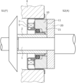
도 1은 본 발명의 실시예 1에 있어서의 메커니컬 시일의 일례를 나타내는 종단면도이다.
도 2는 실시예 1에 있어서의 정지(靜止) 밀봉환의 슬라이딩면을 축방향으로부터 본 도면이다.
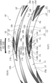
도 3은 실시예 1에 있어서의 정지 밀봉환의 슬라이딩면을 축방향으로부터 본 확대도이다.
도 4는 도 3의 A-A 단면도이다.
도 5는 실시예 1에 있어서의 제1 동압 발생홈과 제2 동압 발생홈의 지름 방향의 깊이 분포를 나타내는 도면이다.
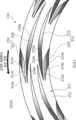
도 6은 실시예 1에 있어서의 정지 밀봉환의 슬라이딩면을 축방향으로부터 본 확대도이다.
도 7은 본 발명의 실시예 2에 있어서의 정지 밀봉환의 슬라이딩면을 축방향으로부터 본 확대도이다.
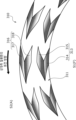
도 8은 본 발명의 실시예 3에 있어서의 정지 밀봉환의 슬라이딩면을 축방향으로부터 본 확대도이다.
도 9는 본 발명의 실시예 4에 있어서의 정지 밀봉환의 슬라이딩면을 축방향으로부터 본 확대도이다.
도 10은 도 9의 B-B 단면도이다.
도 11은 본 발명의 실시예 5에 있어서의 정지 밀봉환의 슬라이딩면을 축방향으로부터 본 확대도이다.
도 12는 변형예 1에 있어서의 정지 밀봉환의 슬라이딩면을 축방향으로부터 본 확대도이다.
도 13은 변형예 2에 있어서의 정지 밀봉환의 슬라이딩면을 축방향으로부터 본 확대도이다.
도 14는 변형예 3에 있어서의 정지 밀봉환의 슬라이딩면을 축방향으로부터 본 도면이다.
도 15는 변형예 4에 있어서의 정지 밀봉환의 슬라이딩면을 축방향으로부터 본 도면이다.1 is a longitudinal cross-sectional view showing an example of a mechanical seal in Example 1 of the present invention.
Fig. 2 is a view of the sliding surface of the stationary sealing ring in Example 1 as seen from the axial direction.
Fig. 3 is an enlarged view of the sliding surface of the stationary seal ring in Example 1 as seen from the axial direction.
Figure 4 is a cross-sectional view taken along line AA of Figure 3.
Figure 5 is a diagram showing the radial depth distribution of the first dynamic pressure generation groove and the second dynamic pressure generation groove in Example 1.
Fig. 6 is an enlarged view of the sliding surface of the stationary seal ring in Example 1 as seen from the axial direction.
Fig. 7 is an enlarged view of the sliding surface of the stationary seal ring in Example 2 of the present invention as seen from the axial direction.
Fig. 8 is an enlarged view of the sliding surface of the stationary seal ring in Example 3 of the present invention as seen from the axial direction.
Fig. 9 is an enlarged view of the sliding surface of the stationary seal ring in Example 4 of the present invention as seen from the axial direction.
Figure 10 is a cross-sectional view taken along line BB of Figure 9.
Fig. 11 is an enlarged view of the sliding surface of the stationary seal ring in Example 5 of the present invention as seen from the axial direction.
Fig. 12 is an enlarged view of the sliding surface of the stationary seal ring in Modification Example 1 as seen from the axial direction.
Fig. 13 is an enlarged view of the sliding surface of the stationary seal ring in Modification Example 2 as seen from the axial direction.
Fig. 14 is a view showing the sliding surface of the stationary seal ring in Modification Example 3 as seen from the axial direction.
Fig. 15 is a view showing the sliding surface of the stationary seal ring in Modification Example 4 as seen from the axial direction.
본 발명에 따른 슬라이딩 부품을 실시하기 위한 형태를 실시예에 기초하여 이하에 설명한다.A mode for implementing the sliding part according to the present invention will be described below based on examples.
실시예 1Example 1
실시예 1에 따른 슬라이딩 부품으로서의 메커니컬 시일에 대해, 도 1 내지 도 6을 참조하여 설명한다. 또한, 본 실시예에 있어서는, 메커니컬 시일의 안쪽 공간(S1)에 피밀봉 유체(F)가 존재하고, 바깥 공간(S2)에 대기(A)가 존재하고 있고, 메커니컬 시일을 구성하는 슬라이딩환의 내경측을 피밀봉 유체측(고압측), 외경측을 누설측(저압측)으로 하여 설명한다. 또한, 설명의 편의상, 도면에 있어서, 슬라이딩면에 형성되는 홈 등에 천심(淺深)을 나타내는 그라데이션을 부여하는 경우도 있다.The mechanical seal as a sliding part according to Example 1 will be described with reference to FIGS. 1 to 6. Furthermore, in this embodiment, the fluid to be sealed (F) exists in the inner space (S1) of the mechanical seal, the atmosphere (A) exists in the outer space (S2), and the inner diameter of the sliding ring constituting the mechanical seal is The explanation will be made with the side being the sealed fluid side (high pressure side) and the outer diameter side being the leak side (low pressure side). Additionally, for convenience of explanation, in the drawings, a gradation indicating shallowness may be given to grooves formed on the sliding surface, etc.
도 1에 나타나는 자동차용의 메커니컬 시일은, 슬라이딩면의 내경측으로부터 외경측을 향하여 누설되고자 하는 안쪽 공간(S1) 내의 피밀봉 유체(F)를 밀봉하고 바깥 공간(S2)이 대기(A)에 통하는 아웃사이드형의 것이다. 또한, 본 실시예에서는, 피밀봉 유체(F)가 고압의 기체이며, 대기(A)가 피밀봉 유체(F)보다 저압의 기체인 형태를 예시한다.The mechanical seal for automobiles shown in FIG. 1 seals the fluid (F) to be sealed in the inner space (S1) that is about to leak from the inner diameter side of the sliding surface toward the outer diameter side, and seals the outer space (S2) to the atmosphere (A). It is an outside type that works. Additionally, in this embodiment, the sealed fluid F is a high-pressure gas, and the atmosphere A is a lower-pressure gas than the sealed fluid F.
메커니컬 시일은, 슬라이딩 부품으로서의 회전 밀봉환(20)과, 슬라이딩 부품으로서의 정지 밀봉환(10)으로 주로 구성되어 있다. 회전 밀봉환(20)은, 원환상을 이루고, 회전축(1)에 슬리브(2)를 통하여 회전축(1)과 함께 회전 가능한 상태로 마련되어 있다. 정지 밀봉환(10)은, 원환상을 이루고, 피장착 기기인 하우징(4)에 고정된 시일 커버(5)에 비회전 상태 또한 축방향으로 이동 가능한 상태로 마련되어 있다. 탄성 부재(7)에 의해 정지 밀봉환(10)이 축방향으로 부세(付勢)됨으로써, 정지 밀봉환(10)의 슬라이딩면(11)과 회전 밀봉환(20)의 슬라이딩면(21)이 서로 밀접 슬라이딩하도록 되어 있다. 또한, 회전 밀봉환(20)의 슬라이딩면(21)은 평탄면으로 형성되어 있고, 이 평탄면에는 홈 등의 오목부가 마련되어 있지 않다.The mechanical seal is mainly composed of a rotating
정지 밀봉환(10) 및 회전 밀봉환(20)은, 대표적으로는 SiC(경질 재료)끼리, 또는 SiC(경질 재료)와 카본(연질 재료)의 조합으로 형성되지만, 이에 한정하지 않고, 슬라이딩 재료는 메커니컬 시일용 슬라이딩 재료로서 사용되고 있는 것이라면 적용 가능하다. 또한, SiC로서는, 보론, 알루미늄, 카본 등을 소결 조제로 한 소결체를 비롯하여, 성분, 조성이 상이한 2종류 이상의 상으로 이루어지는 재료, 예를 들면, 흑연 입자가 분산된 SiC, SiC와 Si로 이루어지는 반응 소결 SiC, SiC-TiC, SiC-TiN 등이 있고, 카본으로서는, 탄소질과 흑연질이 혼합된 카본을 비롯하여, 수지 성형 카본, 소결 카본 등을 이용할 수 있다. 또한, 상기 슬라이딩 재료 이외로는, 금속 재료, 수지 재료, 표면 개질 재료(코팅 재료), 복합 재료 등도 적용 가능하다.The
도 2 및 도 3에 나타나는 바와 같이, 정지 밀봉환(10)에 대하여 상대측 밀봉환인 회전 밀봉환(20)이, 실선 화살표로 나타내는 바와 같이 반시계 방향으로 상대 슬라이딩하도록 되어 있다. 이하, 이 상태를 정지 밀봉환(10)과 회전 밀봉환(20)의 순방향의 상대 회전으로 하여 설명한다.As shown in Figs. 2 and 3, the
정지 밀봉환(10)의 슬라이딩면(11)에는, 내경측에 복수의 동압 발생 기구(13)와, 외경측에 복수의 동압 발생 기구(16)가 마련되어 있다. 동압 발생 기구(13)는, 슬라이딩면(11)의 내경측에 있어서 둘레 방향으로 균등하게 배설(配設)(본 실시예에서는 12개)되어 있다. 동압 발생 기구(16)는, 슬라이딩면(11)의 외경측에 있어서 둘레 방향으로 균등하게 배설(본 실시예에서는 12개)되어 있다. 또한, 본 실시예에서는, 동압 발생 기구(13, 16)는, 지름 방향으로 나란히 배치되어 있지만, 이에 한정되지 않고, 동압 발생 기구(13, 16)는, 둘레 방향으로 어긋나게 배치되어도 좋다.The sliding
또한, 슬라이딩면(11)에 있어서의 동압 발생 기구(13, 16) 이외의 부분은 동일 평면 상에 배치된 평탄면을 가지는 랜드(12)로 형성되어 있다. 랜드(12)의 평탄면이 회전 밀봉환(20)의 슬라이딩면(21)과 실질적으로 슬라이딩하는 슬라이딩면으로서 기능하고 있다.Additionally, portions of the sliding
도 3에 나타나는 바와 같이, 내경측의 동압 발생 기구(13)는, 제1 동압 발생홈(14)과, 제2 동압 발생홈(15)으로 구성되어 있다. 제1 동압 발생홈(14)은, 안쪽 공간(S1)과 연통하고, 정지 밀봉환(10)의 내주면(10g)으로부터 상대 회전 방향에 대하여 기울어서 외경 방향으로 직선 형상으로 연장되어 있다. 제2 동압 발생홈(15)은, 제1 동압 발생홈(14)의 외경측의 단부로부터 상대 회전 방향에 대하여 제1 동압 발생홈(14)과 역방향으로 기울어서 외경 방향으로 직선 형상으로 연장되어 있다. 여기에서 홈이 「기운다」란, 홈이 길이 방향으로 상대 회전 방향(즉, 둘레 방향)과 평행하게 연장되어 있지 않고, 또한, 상대 회전 방향과는 직교하지 않고 연장되어 있는 것을 의미한다. 또한, 홈의 일부의 개소가 상대 회전 방향(즉, 둘레 방향)과 평행하거나 직교하여도 좋다.As shown in FIG. 3, the dynamic
또한, 제1 동압 발생홈(14)과 제2 동압 발생홈(15)은, 지름 방향으로 나란히 배치되어 있고, 단부끼리가 연결되어 있다.Additionally, the first dynamic
또한, 제2 동압 발생홈(15)은, 제1 동압 발생홈(14)보다 홈의 연신 방향에 있어서의 홈의 길이, 바꿔 말하면 홈의 길이 방향에 있어서의 홈의 길이, 혹은 홈의 기울기 방향에 있어서의 홈의 길이가 길고, 상세하게는 홈의 연신 방향에 있어서의 둘레 방향 성분이 길다. 또한, 제1 동압 발생홈(14)과 제2 동압 발생홈(15)은, 홈의 연신 방향에 있어서의 지름 방향 성분이 대략 동일한 길이이다.In addition, the second dynamic
또한, 인접하는 제2 동압 발생홈(15)끼리는 그 단부가 지름 방향으로 중첩하여 배치되어 있다. 상세하게는, 제2 동압 발생홈(15)의 상대 회전 상류측의 단부, 즉, 단연(端緣)(15f)을 가지는 단부가, 둘레 방향으로 인접하는 제2 동압 발생홈(15′)의 상대 회전 하류측의 단부, 즉, 단연(15e′)을 가지는 단부보다 외경측에서 지름 방향으로 중첩하도록 배치되어 있다.Additionally, the ends of the adjacent second dynamic
제1 동압 발생홈(14)은, 바닥면(14a)과, 측면(14b, 14c)으로 구성되어 있다. 바닥면(14a)은, 랜드(12)의 평탄면에 대하여 경사져서 직선 형상으로 연장되어 있다. 측면(14b, 14c)은, 바닥면(14a)의 둘레 방향 양 단연으로부터 기립하고 있다. 또한, 제1 동압 발생홈(14)의 내경측의 단부에는, 안쪽 공간(S1)과 연통하는 개구(14A)가 형성되어 있다.The first dynamic
도 4에 나타나는 바와 같이, 제1 동압 발생홈(14)은, 안쪽 공간(S1)과 연통하는 개구(14A)에 위치하는 바닥면(14a)의 내경측의 단연(14d)이 가장 깊고, 바닥면(14a)의 외경측의 단연(14e)이 가장 얕아지도록 랜드(12)의 평탄면에 대하여 그 지름 방향으로 경사져 있다. 즉, 제1 동압 발생홈(14)은, 바닥면(14a)의 내경측의 단연(14d)으로부터 외경측의 단연(14e)을 향함에 따라 깊이가 얕아지도록 형성되어 있다. 또한, 제1 동압 발생홈(14)은, 도 2 및 도 3에 있어서 실선 화살표로 나타내는 순방향의 상대 회전에 대하여, 상대 회전 상류측이 깊고, 상대 회전 하류측이 얕아지도록 형성되어 있다.As shown in FIG. 4, the first dynamic
도 3에 나타나는 바와 같이, 제2 동압 발생홈(15)은, 바닥면(15a)과, 측면(15b, 15c)과, 내경측의 단면(15d)으로 구성되어 있다. 바닥면(15a)은, 랜드(12)의 평탄면에 대하여 경사져서 직선 형상으로 연장되어 있다. 측면(15b, 15c)은, 바닥면(15a)의 둘레 방향 양 단연으로부터 기립하고 있다. 내경측의 단면(15d)은, 바닥면(15a)의 내경단으로부터 기립하고, 측면(15b, 15c)에 직교 연결되어 있다.As shown in FIG. 3, the second dynamic
도 4에 나타나는 바와 같이, 제2 동압 발생홈(15)은, 바닥면(15a)의 내경측의 단연(15e)이 가장 깊고, 바닥면(15a)의 외경측의 단연(15f)이 가장 얕아지도록 랜드(12)의 평탄면에 대하여 그 지름 방향으로 경사져 있다. 즉, 제2 동압 발생홈(15)은, 바닥면(15a)의 내경측의 단연(15e)으로부터 외경측의 단연(15f)을 향함에 따라 깊이가 얕아지도록 형성되어 있다. 또한, 제2 동압 발생홈(15)은, 도 2 및 도 3에 있어서 실선 화살표로 나타내는 순방향의 상대 회전에 대하여, 상대 회전 상류측이 얕고, 상대 회전 하류측이 깊어지도록 형성되어 있다.As shown in FIG. 4, the
이와 같이, 동압 발생 기구(13)를 구성하는 제1 동압 발생홈(14)과 제2 동압 발생홈(15)은, 상대 회전 방향에 대한 깊이 관계가 반대로 되어 있다.In this way, the first dynamic
또한, 제1 동압 발생홈(14)의 바닥면(14a)의 내경측의 단연(14d)에 있어서의 깊이(D1)는, 제2 동압 발생홈(15)의 바닥면(15a)의 내경측의 단연(15e)에 있어서의 깊이(D2)와 동일(D1=D2)하게 형성되어 있다. 바꿔 말하면, 제1 동압 발생홈(14)과 제2 동압 발생홈(15)의 가장 깊은 개소는 동일한 깊이로 되어 있다. 또한, 도 4에 있어서, 제1 동압 발생홈(14) 및 제2 동압 발생홈(15)에 있어서의 깊이(D1, D2)는, 설명의 편의상, 실제보다 깊게 표현하고 있다. 또한, 본 실시예에서는, 제1 동압 발생홈(14)의 바닥면(14a)의 외경측의 단연(14e)과, 제2 동압 발생홈(15)의 바닥면(15a)의 외경측의 단연(15f)은, 랜드(12)의 평탄면과 동일 평면 상에 배치되어 있고, 실질적으로 깊이를 가지고 있지 않다.In addition, the depth D1 at the
또한, 본 실시예에서는, 도 4에 있어서, 제1 동압 발생홈(14)의 바닥면(14a)의 랜드(12)의 평탄면에 대한 지름 방향의 기울기가, 제2 동압 발생홈(15)의 바닥면(15a)의 랜드(12)의 평탄면에 대한 지름 방향의 기울기보다 크게 표현되어 있다. 이것은, 도 4가 도 3의 A-A 단면도이며, 전술한 바와 같이, 제2 동압 발생홈(15)이 제1 동압 발생홈(14)보다 홈의 연신 방향에 있어서의 홈의 길이가 길고, 상세하게는 홈의 연신 방향에 있어서의 둘레 방향 성분이 길게 형성되어 있기 때문이다.In addition, in this embodiment, in FIG. 4, the radial inclination of the
또한, 본 실시예에서는, 도 5에 나타나는 바와 같이, 제1 동압 발생홈(14)과 제2 동압 발생홈(15)은, 지름 방향의 깊이 분포가 동일한 기울기 정도가 되도록 형성되어 있다.Additionally, in this embodiment, as shown in FIG. 5, the first dynamic
도 3에 나타나는 바와 같이, 외경측의 동압 발생 기구(16)는, 제1 동압 발생홈(17)과, 제2 동압 발생홈(18)으로 구성되어 있다. 제1 동압 발생홈(17)은, 바깥 공간(S2)과 연통하고, 정지 밀봉환(10)의 외주면(10h)으로부터 상대 회전 방향에 대하여 기울어서 내경 방향으로 직선 형상으로 연장되어 있다. 제2 동압 발생홈(18)은, 제1 동압 발생홈(17)의 내경측의 단부로부터 상대 회전 방향에 대하여 제1 동압 발생홈(17)과 역방향으로 기울어서 내경 방향으로 직선 형상으로 연장되어 있다.As shown in FIG. 3, the dynamic
또한, 제1 동압 발생홈(17)과 제2 동압 발생홈(18)은, 지름 방향으로 나란히 배치되어 있고, 단부끼리가 연결되어 있다.Additionally, the first dynamic
또한, 제2 동압 발생홈(18)은, 제1 동압 발생홈(17)보다 홈의 연신 방향에 있어서의 홈의 길이가 길고, 상세하게는 홈의 연신 방향에 있어서의 둘레 방향 성분이 길다. 또한, 제1 동압 발생홈(17)과 제2 동압 발생홈(18)은, 홈의 연신 방향에 있어서의 지름 방향 성분이 대략 동일한 길이이다.Additionally, the second dynamic
또한, 인접하는 제2 동압 발생홈(18)끼리는 그 단부가 지름 방향으로 중첩하여 배치되어 있다. 상세하게는, 제2 동압 발생홈(18)의 상대 회전 상류측의 단부, 즉, 단연(18f)을 가지는 단부가, 둘레 방향으로 인접하는 제2 동압 발생홈(18′)의 상대 회전 하류측의 단부, 즉, 단연(18e′)을 가지는 단부보다 내경측에서 지름 방향으로 중첩하도록 배치되어 있다.Additionally, adjacent second dynamic
제1 동압 발생홈(17)은, 바닥면(17a)과, 측면(17b, 17c)으로 구성되어 있다. 바닥면(17a)은, 랜드(12)의 평탄면에 대하여 경사져서 직선 형상으로 연장되어 있다. 측면(17b, 17c)은, 바닥면(17a)의 둘레 방향 양 단연으로부터 기립하고 있다. 또한, 제1 동압 발생홈(17)의 외경측의 단부에는, 바깥 공간(S2)과 연통하는 개구(17A)가 형성되어 있다.The first dynamic
설명의 편의상, 도시를 생략하지만, 제1 동압 발생홈(17)은, 바깥 공간(S2)과 연통하는 개구(17A)에 위치하는 바닥면(17a)의 외경측의 단연(17d)이 가장 깊고, 바닥면(17a)의 내경측의 단연(17e)이 가장 얕아지도록 랜드(12)의 평탄면에 대하여 그 지름 방향으로 경사져 있다. 즉, 제1 동압 발생홈(17)은, 바닥면(17a)의 외경측의 단연(17d)으로부터 내경측의 단연(17e)을 향함에 따라 깊이가 얕아지도록 형성되어 있다. 또한, 제1 동압 발생홈(17)은, 도 2 및 도 3에 있어서 실선 화살표로 나타내는 순방향의 상대 회전에 대하여, 상대 회전 상류측이 깊고, 상대 회전 하류측이 얕아지도록 형성되어 있다.For convenience of explanation, the illustration is omitted, but the first dynamic
제2 동압 발생홈(18)은, 바닥면(18a)과, 측면(18b, 18c)과, 외경측의 단면(18d)으로 구성되어 있다. 바닥면(18a)은, 랜드(12)의 평탄면에 대하여 경사져서 직선 형상으로 연장되어 있다. 측면(18b, 18c)은, 바닥면(18a)의 둘레 방향 양 단연으로부터 기립하고 있다. 외경측의 단면(18d)은, 바닥면(18a)의 내경단으로부터 기립하고, 측면(18b, 18c)에 직교 연결되어 있다. The second dynamic
설명의 편의상, 도시를 생략하지만, 제2 동압 발생홈(18)은, 바닥면(18a)의 외경측의 단연(18e)이 가장 깊고, 바닥면(18a)의 내경측의 단연(18f)이 가장 얕아지도록 랜드(12)의 평탄면에 대하여 그 지름 방향으로 경사져 있다. 즉, 제2 동압 발생홈(18)은, 바닥면(18a)의 외경측의 단연(18e)으로부터 바닥면(18a)의 내경측의 단연(18f)을 향함에 따라 깊이가 얕아지도록 형성되어 있다. 또한, 제2 동압 발생홈(18)은, 도 2 및 도 3에 있어서 실선 화살표로 나타내는 순방향의 상대 회전에 대하여, 상대 회전 상류측이 얕고, 상대 회전 하류측이 깊어지도록 형성되어 있다. For convenience of explanation, the illustration is omitted, but in the second dynamic
이와 같이, 동압 발생 기구(16)를 구성하는 제1 동압 발생홈(17)과 제2 동압 발생홈(18)은, 상대 회전 방향에 대한 깊이 관계가 반대로 되어 있다. 또한, 동압 발생 기구(16)는, 동압 발생 기구(13)에 대하여 슬라이딩면의 지름 방향에 있어서의 도시하지 않는 중앙선을 기준으로 하여, 소위, 경상(鏡像) 관계가 되도록 제1 동압 발생홈(17)과 제2 동압 발생홈(18)이 형성되어 있다. In this way, the first dynamic
이어서, 정지 밀봉환(10)과 회전 밀봉환(20)의 순방향의 상대 회전시의 동작에 대해서 도 3을 사용하여 설명한다. 또한, 도 3에 있어서는, 피밀봉 유체(F)의 흐름을 검은색 화살표, 대기(A)의 흐름을 흰색 화살표로 나타내고 있다. Next, the operation of the
우선, 회전 밀봉환(20)이 회전하고 있지 않는 정지시에는, 피밀봉 유체(F)가 개구(14A)로부터 제1 동압 발생홈(14) 내로 유입됨과 동시에, 제1 동압 발생홈(14) 내로 유입된 피밀봉 유체(F)가 바닥면(14a)의 외경측의 단연(14e)을 넘어, 외경측과 연결되는 제2 동압 발생홈(15)에도 근소하게 유입되어 있다. 또한, 대기(A)가 제1 동압 발생홈(17)에 개구(17A)로부터 유입됨과 동시에, 제1 동압 발생홈(17) 내로 유입된 대기(A)가 바닥면(17a)의 내경측의 단연(17e)을 넘어, 내경측과 연결되는 제2 동압 발생홈(18)에도 근소하게 유입되어 있다. 또한, 탄성 부재(7)에 의해 정지 밀봉환(10)이 회전 밀봉환(20)측으로 부세되어 있기 때문에 슬라이딩면(11, 21)끼리가 접촉 상태로 되어 있어, 슬라이딩면(11, 21) 사이의 피밀봉 유체(F)에 있어서, 바깥 공간(S2)으로 누출되는 양은 거의 없다. First, when the
도 3에 나타나는 바와 같이, 회전 밀봉환(20)이 정지 밀봉환(10)에 대하여 순방향으로 상대 회전하면, 제1 동압 발생홈(14) 내 및 제2 동압 발생홈(15) 내의 피밀봉 유체(F)가 슬라이딩면(21)과의 전단에 의해 회전 밀봉환(20)의 회전 방향으로 추종 이동한다. As shown in FIG. 3, when the
구체적으로는, 제1 동압 발생홈(14) 내에서는, 피밀봉 유체(F)가 화살표(F1)로 나타내는 바와 같이 개구(14A) 근방으로부터 외경측의 단연(14e)을 향하여 이동한다. 이에 따라 개구(14A) 근방의 유체압은, 주변의 유체압보다 상대적으로 낮아진다. 바꿔 말하면, 개구(14A) 근방에는 상대적인 부압이 발생하고, 안쪽 공간(S1)의 피밀봉 유체(F)가 화살표(F2)로 나타내는 바와 같이 제1 동압 발생홈(14) 내로 흡입된다. Specifically, within the first dynamic
또한, 제1 동압 발생홈(14) 내에서는, 개구(14A)에 위치하는 내경측의 단연(14d)의 깊이(D1)가 가장 깊기 때문에(도 4 참조), 제1 동압 발생홈(14) 내로 피밀봉 유체(F)를 많이 유입시킬 수 있다. In addition, within the first dynamic
또한, 제1 동압 발생홈(14) 내에서는, 피밀봉 유체(F)가 화살표(F3)로 나타내는 바와 같이 외경측의 단연(14e)을 향하여 측면(14b)을 따라 이동한다. 단연(14e)을 향하여 이동한 피밀봉 유체(F)는, 단연(14e)과 측면(14b)에 의해 형성되는 모서리부(14B) 및 그 근방에서 압력이 높아진다. 즉, 제1 동압 발생홈(14)의 모서리부(14B) 및 그 근방에서 정압이 발생한다. Additionally, within the first dynamic
또한, 제1 동압 발생홈(14)은, 내경측의 단연(14d)으로부터 외경측의 단연(14e)을 향함에 따라 깊이가 얕아지기 때문에, 피밀봉 유체(F)는, 제1 동압 발생홈(14)의 모서리부(14B)를 향하여 이동해 가는 과정에서도 압력이 높아지기 쉽도록 되어 있다. 또한, 회전 밀봉환(20)의 회전 속도가 저속임에 따라 피밀봉 유체(F)의 이동량이 적어도, 제1 동압 발생홈(14)의 모서리부(14B) 및 그 근방에서 정압이 발생하기 쉽도록 되어 있다. Additionally, since the depth of the first dynamic
또한, 제1 동압 발생홈(14)의 모서리부(14B) 및 그 근방에서 발생한 정압에 의한 힘에 의해, 슬라이딩면(11, 21) 사이가 약간 이간된다(도시 생략). 이에 따라, 슬라이딩면(11, 21) 사이에는, 주로 화살표(F4)로 나타내는 바와 같이 제1 동압 발생홈(14) 내의 피밀봉 유체(F)가 유출된다. 이와 같이 슬라이딩면(11, 21) 사이에 피밀봉 유체(F)가 개재함으로써 윤활성이 향상되어, 슬라이딩면(11, 21)끼리의 마모를 억제할 수 있다. 또한, 슬라이딩면(11, 21)끼리의 부상(浮上) 거리가 근소하기 때문에, 제1 동압 발생홈(14)으로부터 슬라이딩면(11, 21) 사이로 유출되는 피밀봉 유체(F)는 적고, 또한 슬라이딩면(11, 21) 사이로 유출되어도 둘레 방향으로 인접하는 동압 발생 기구(13)의 제2 동압 발생홈(15)에 의해 회수되기 때문에(화살표(F6) 참조), 바깥 공간(S2)으로는 거의 누출되지 않도록 되어 있다. Additionally, the sliding
또한, 제2 동압 발생홈(15) 내에서는, 피밀봉 유체(F)가 화살표(F5)에 나타내는 바와 같이 외경측의 단연(15f)으로부터 내경측의 단연(15e)을 향하여 이동한다. 제2 동압 발생홈(15)은, 외경측의 단연(15f)으로부터 내경측의 단연(15e)을 향함에 따라 깊이가 깊어지기 때문에, 제2 동압 발생홈(15) 내에서는 동압이 거의 발생하지 않는다. Additionally, within the second dynamic
상세하게는, 제2 동압 발생홈(15)의 외경측의 단연(15f) 근방에는 상대적인 부압이 발생하고, 내경측의 단연(15e) 근방에는 상대적인 정압이 발생하지만, 이들 부압, 정압의 절대값은 매우 작다. 이 때문에, 전술한 바와 같이, 제2 동압 발생홈(15)에 있어서는, 제1 동압 발생홈(14)에 비하여 현격히 동압이 발생하기 어렵도록 되어 있다. In detail, a relative negative pressure is generated near the
또한, 둘레 방향에 있어서 상대 회전 상류측에 인접하는 동압 발생 기구(13′)의 제1 동압 발생홈(14′)으로부터 슬라이딩면(11, 21) 사이로 유출된 피밀봉 유체(F)가, 화살표(F6)로 나타내는 바와 같이 제2 동압 발생홈(15) 내로 흡입된다. 또한, 제2 동압 발생홈(15)으로는, 동일한 동압 발생 기구(13)의 제1 동압 발생홈(14)의 단연(14e)을 뛰어넘은 피밀봉 유체(F)의 일부가 유입된다. 이 점에서도, 제2 동압 발생홈(15)에서는 동압이 발생하기 어렵도록 되어 있다. In addition, the fluid F to be sealed flowing out between the sliding
또한, 도 5에 나타나는 바와 같이, 제1 동압 발생홈(14)과 제2 동압 발생홈(15)은, 지름 방향의 깊이 분포가 동일한 직선 형상의 기울기 정도가 되도록 바닥면(14a, 15a)이 경사져 있음으로써, 제1 동압 발생홈(14)에서는, 정압이 한층 더 발생하기 쉽도록 되어 있고, 제2 동압 발생홈(15)에서는, 부압이 발생하기 어렵도록 되어 있다. 또한, 이들의 기울기는 직선 형상이 아니라 곡선 형상이라도 좋다. 또한, 제1 동압 발생홈(14)의 기울기와 제2 동압 발생홈(15)의 기울기는, 지름 방향의 깊이 분포에 있어서의 기울기 정도가 동일하지 않아도 좋다. In addition, as shown in FIG. 5, the bottom surfaces 14a and 15a of the first dynamic
또한, 동압 발생 기구(16)에 있어서의 대기(A)의 흐름에 대해서는, 전술한 동압 발생 기구(13)에 있어서의 피밀봉 유체(F)와 대략 동일한 흐름(도 3에 나타나는 흰색 화살표를 참조)으로 하여 설명할 수 있는 점에서, 상세한 설명을 생략한다. In addition, the flow of the atmosphere A in the dynamic
이어서, 정지 밀봉환(10)과 회전 밀봉환(20)의 역방향으로의 상대 회전시의 동작에 대해서 도 6을 사용하여 설명한다. 또한, 도 6에 있어서도 도 3과 마찬가지로, 피밀봉 유체(F)의 흐름을 검은색 화살표, 대기(A)의 흐름을 흰색 화살표로 나타내고 있다. 또한, 회전 밀봉환(20)의 정지시의 양태에 대해서는 동일하기 때문에, 설명을 생략한다. Next, the operation of the
도 6에 나타나는 바와 같이, 회전 밀봉환(20)이 정지 밀봉환(10)에 대하여 역방향으로 상대 회전하면, 제1 동압 발생홈(14) 내 및 제2 동압 발생홈(15) 내의 피밀봉 유체(F)가 슬라이딩면(21)과의 전단에 의해 회전 밀봉환(20)의 회전 방향으로 추종 이동한다. As shown in FIG. 6, when the
구체적으로는, 제1 동압 발생홈(14) 내에서는, 피밀봉 유체(F)가 화살표(F11)로 나타내는 바와 같이 외경측의 단연(14e)으로부터 개구(14A)를 향하여 이동한다. 제1 동압 발생홈(14)은, 외경측의 단연(14e)으로부터 내경측의 단연(14d)을 향함에 따라 깊이가 깊어지기 때문에, 제1 동압 발생홈(14) 내에서 동압은 거의 발생하지 않는다. Specifically, within the first dynamic
상세하게는, 제1 동압 발생홈(14)의 외경측의 단연(14e) 근방에는 상대적인 부압이 발생하고, 내경측의 단연(14d) 근방에는 상대적인 정압이 발생하지만, 이들 부압, 정압의 절대값은 매우 작다. 이 때문에, 전술한 바와 같이, 제1 동압 발생홈(14)에 있어서는, 제2 동압 발생홈(15)에 비하여 현격히 동압이 발생하기 어렵도록 되어 있다. In detail, a relative negative pressure is generated near the
또한, 제1 동압 발생홈(14)은, 개구(14A)에 의해 안쪽 공간(S1)과 연통하고 있기 때문에, 제1 동압 발생홈(14) 내에 동압이 거의 발생하지 않게 되어 있다. 이 점에서, 슬라이딩면(11, 21) 사이로부터 제1 동압 발생홈(14) 내로의 피밀봉 유체(F)의 흡입은 거의 발생하지 않는다. Additionally, since the first dynamic
또한, 제2 동압 발생홈(15) 내에서는, 피밀봉 유체(F)가 화살표(F12)로 나타내는 바와 같이 내경측의 단연(15e)으로부터 외경측의 단연(15f)을 향하여 이동한다. 이에 따라 내경측의 단연(15e)의 유체압은, 주변의 유체압보다 상대적으로 낮아진다. 바꿔 말하면, 내경측의 단연(15e) 근방에는 상대적인 부압이 발생하고, 둘레 방향에 있어서 상대 회전 상류측에 인접하는 동압 발생 기구(13′)의 제2 동압 발생홈(15′)으로부터 슬라이딩면(11, 21) 사이로 유출된 피밀봉 유체(F)가 화살표(F13)로 나타내는 바와 같이 제2 동압 발생홈(15) 내로 흡입된다. 또한, 전술한 바와 같이, 제1 동압 발생홈(14)에 있어서는, 동압이 거의 발생하지 않기 때문에, 제2 동압 발생홈(15)의 내경측의 단연(15e)의 유체압은, 제1 동압 발생홈(14)의 외경측의 단연(14e)의 유체압보다 상대적으로 낮아진다. 이 때문에, 슬라이딩면(11, 21) 사이의 피밀봉 유체(F)는, 제1 동압 발생홈(14)보다 제2 동압 발생홈(15) 내로 흡입되기 쉽도록 되어 있다. Additionally, within the second dynamic
또한, 제2 동압 발생홈(15) 내에서는, 내경측의 단연(15e)의 깊이(D2)가 가장 깊기 때문에(도 4 참조), 제2 동압 발생홈(15) 내로 피밀봉 유체(F)를 많이 유입시킬 수 있다. In addition, within the second dynamic
또한, 제2 동압 발생홈(15) 내에서는, 피밀봉 유체(F)가 화살표(F14)로 나타내는 바와 같이 외경측의 단연(15f)을 향하여 측면(15b)을 따라 이동한다. 단연(15f)을 향하여 이동한 피밀봉 유체(F)는, 단연(15f)과 측면(15b)에 의해 형성되는 모서리부(15B) 및 그 근방에서 압력이 높아진다. 즉, 제2 동압 발생홈(15)의 모서리부(15B) 및 그 근방에서 정압이 발생한다. Additionally, within the second dynamic
또한, 제2 동압 발생홈(15)은, 내경측의 단연(15e)으로부터 외경측의 단연(15f)을 향함에 따라 깊이가 얕아지기 때문에, 피밀봉 유체(F)는, 제2 동압 발생홈(15)의 모서리부(15B)를 향하여 이동해 가는 과정에서도 압력이 높아지기 쉽도록 되어 있다. 또한, 회전 밀봉환(20)의 회전 속도가 저속임에 따라 피밀봉 유체(F)의 이동량이 적어도, 제2 동압 발생홈(15)의 모서리부(15B) 및 그 근방에서 정압이 발생하기 쉽도록 되어 있다. Additionally, since the depth of the second dynamic
또한, 제2 동압 발생홈(15)은, 제1 동압 발생홈(14)보다 연신 방향으로 길고, 상세하게는 홈의 연신 방향에 있어서의 둘레 방향 성분이 길게 형성되어 있기 때문에, 피밀봉 유체(F)는, 제2 동압 발생홈(15)의 모서리부(15B)를 향하여 이동해 가는 과정에서 압력이 한층 더 높아지기 쉽도록 되어 있다. In addition, the second dynamic
또한, 제2 동압 발생홈(15)의 모서리부(15B) 및 그 근방에서 발생한 정압에 의한 힘에 의해, 슬라이딩면(11, 21) 사이가 약간 이간된다(도시 생략). 이에 따라, 슬라이딩면(11, 21) 사이로는, 주로 화살표(F15)로 나타내는 바와 같이 제2 동압 발생홈(15) 내의 피밀봉 유체(F)가 유출된다. 또한, 제2 동압 발생홈(15)의 외경측의 단연(15f)은, 랜드(12)의 평탄면과 동일 평면 상에 배치되어 있기 때문에, 모서리부(15B)뿐만 아니라, 외경측의 단연(15f)에 걸쳐 넓은 범위에서 정압이 발생한다. 이와 같이 슬라이딩면(11, 21) 사이에 피밀봉 유체(F)가 개재함으로써 윤활성이 향상되어, 슬라이딩면(11, 21)끼리의 마모를 억제할 수 있다. Additionally, the sliding
또한, 동압 발생 기구(16)에 있어서의 대기(A)의 흐름에 대해서는, 전술한 동압 발생 기구(13)에 있어서의 피밀봉 유체(F)와 대략 동일한 흐름(도 6에 나타나는 흰색 화살표를 참조)으로 설명할 수 있는 점에서, 상세한 설명을 생략한다. Additionally, the flow of the atmosphere A in the dynamic
또한, 본 실시예에서는, 도 3에 나타나는 순방향으로의 상대 회전시와, 도 6에 나타나는 역방향으로의 상대 회전시에 있어서, 동압 발생 기구(13, 16) 전체에서 동일한 정도의 정압이 발생한다. Furthermore, in this embodiment, the same degree of static pressure is generated throughout the dynamic
이상 설명한 바와 같이, 동압 발생 기구(13, 16)를 구성하는 제1 동압 발생홈(14, 17)과 제2 동압 발생홈(15, 18)은, 바닥면이 지름 방향으로 동일한 방향으로 경사져 있고, 상대 회전 방향에 대한 깊이 관계가 반대로 되어 있다. 이에 의하면, 순방향으로의 상대 회전(도 3 참조)에 대해서는, 제1 동압 발생홈(14, 17)은, 상대 회전 하류측의 단부, 즉, 단연(14e, 17e)을 가지는 단부를 향함에 따라 얕아지도록 형성되어 있다. 제2 동압 발생홈(15, 18)은, 상대 회전 하류측의 단부, 즉, 단연(15e, 18e)을 가지는 단부를 향함에 따라 깊어지도록 형성되어 있다. 이에 따라, 제1 동압 발생홈(14, 17)에 있어서 정압이 발생하기 쉽고, 또한 제2 동압 발생홈(15, 18)에 있어서 부압이 발생하기 어렵도록 되어 있다. 한편, 역방향으로의 상대 회전(도 6 참조)에 대해서는, 제1 동압 발생홈(14, 17)에 있어서 부압이 발생하기 어렵고, 또한 제2 동압 발생홈(15, 18)에 있어서 정압이 발생하기 쉽도록 되어 있다. 이 때문에, 양 방향으로의 상대 회전에 대하여 슬라이딩면(11)에 마련된 제1, 제2 동압 발생홈 전체에서 정압이 확실하게 발생하여, 슬라이딩면(11, 21)끼리가 이간함으로써, 정지 밀봉환(10)과 회전 밀봉환(20)은 윤활성이 우수하다. As described above, the bottom surfaces of the first dynamic
또한, 동압 발생 기구(13)를 구성하는 제1 동압 발생홈(14)은, 깊은 측의 단부, 즉, 단연(14d)을 가지는 단부가 피밀봉 유체(F)측의 공간인 안쪽 공간(S1)과 연통하고, 동압 발생 기구(16)를 구성하는 제1 동압 발생홈(17)은, 깊은 측의 단부, 즉, 단연(17d)을 가지는 단부가 대기(A)측의 공간인 바깥 공간(S2)과 연통하고 있다. 이에 의하면, 순방향의 상대 회전에 대해서는, 제1 동압 발생홈(14, 17) 내로 피밀봉 유체(F) 또는 대기(A)가 공급되기 쉬워지기 때문에, 정압이 높아지기 쉽다. 또한, 역방향으로의 상대 회전에 대해서는, 제1 동압 발생홈(14, 17) 내로부터 안쪽 공간(S1) 또는 바깥 공간(S2)으로 유체가 배출되기 쉬워지기 때문에, 부압이 발생하기 어렵다. In addition, the first dynamic
또한, 제2 동압 발생홈(15, 18)은, 폐색된 홈이며, 또한 제1 동압 발생홈(14, 17)보다 홈의 연신 방향에 있어서의 홈의 길이가 길고, 상세하게는 홈의 연신 방향에 있어서의 둘레 방향 성분이 길게 형성되어 있다. 이에 의하면, 역방향으로의 상대 회전에 대하여, 안쪽 공간(S1)과도 바깥 공간(S2)과도 연통하지 않는 제2 동압 발생홈(15, 18)에 있어서의 정압 발생 능력이 향상되어 있다. 이 때문에, 양 방향으로의 상대 회전에 대하여, 제1 동압 발생홈(14, 17), 제2 동압 발생홈(15, 18)에 의해 동일한 정도의 정압이 발생한다. In addition, the second dynamic
또한, 제1 동압 발생홈(14, 17)과 제2 동압 발생홈(15, 18)은, 실질적으로 랜드(12)를 개재하지 않고 연결되어 있음으로써, 제1 동압 발생홈(14, 17)과 제2 동압 발생홈(15, 18) 사이에서 유체의 공급이 행해지기 쉽다. 이에 따라, 어느 쪽의 상대 회전 방향이라도, 정압이 발생하는 동압 발생홈으로부터 부압이 발생하기 어려운 동압 발생홈으로 유체가 공급되는 점에서, 부압이 발생하는 동압 발생홈에 있어서 한층 더 부압이 발생하기 어렵도록 되어 있다. In addition, the first dynamic
또한, 제1 동압 발생홈(14, 17)과 제2 동압 발생홈(15, 18)은, 지름 방향으로 나란히 배치되어 있다. 이에 의하면, 슬라이딩면(11)에 있어서의 지름 방향으로 상이한 크기의 동압이 발생하기 때문에, 슬라이딩면(11)의 둘레 방향에 걸쳐 동압이 균등하게 발생하기 쉽다. 또한, 동압 발생 기구(13, 16)를 슬라이딩면(11)의 둘레 방향으로 효율 좋게 배치할 수 있다. Additionally, the first dynamic
또한, 회전 밀봉환(20)의 슬라이딩면(21)은 평탄면이며, 정지 밀봉환(10)의 슬라이딩면(11)에 제1 동압 발생홈(14, 17)과 제2 동압 발생홈(15, 18)이 마련되어 있다. 이에 의하면, 제1 동압 발생홈(14, 17), 제2 동압 발생홈(15, 18) 전체에서 발생하는 동압의 밸런스를 조정하기 쉽다. In addition, the sliding
또한, 제1 동압 발생홈(14, 17)과 제2 동압 발생홈(15, 18)은, 가장 깊은 부분과 가장 얕은 부분의 깊이가 각각 동일하게 형성됨으로써(도 4 참조), 양 방향으로의 상대 회전에 대하여 제1 동압 발생홈(14, 17), 제2 동압 발생홈(15, 18) 전체에서 발생하는 동압의 밸런스를 동일한 정도로 조정하기 쉽다. In addition, the first dynamic
실시예 2Example 2
다음으로, 실시예 2에 따른 슬라이딩 부품에 대해, 도 7을 참조하여 설명한다. 또한, 상기 실시예 1과 동일한 구성, 중복하는 구성의 설명은 생략한다. Next, the sliding part according to Example 2 will be described with reference to FIG. 7. Additionally, descriptions of the same or overlapping configurations as those of
도 7에 나타나는 바와 같이, 본 실시예 2의 정지 밀봉환(210)은, 동압 발생 기구(213)를 구성하는 제1 동압 발생홈(214)과 제2 동압 발생홈(215), 동압 발생 기구(216)를 구성하는 제1 동압 발생홈(217)과 제2 동압 발생홈(218)이 각각 지름 방향으로 이간하여 연결되어 있지 않은 점에서 실시예 1과 상이하며, 그 외의 점은 실시예 1과 동일한 구성으로 되어 있다. As shown in FIG. 7, the
본 실시예 2의 정지 밀봉환(210)은, 제1 동압 발생홈(214, 217)과 제2 동압 발생홈(215, 218)이 지름 방향으로 이간하고 있다. 즉, 제1 동압 발생홈(214)의 바닥면(214a)의 외경측의 단연(214e)과 제2 동압 발생홈(215)의 바닥면(215a)의 내경측의 단연(215e) 사이, 제1 동압 발생홈(217)의 바닥면(217a)의 내경측의 단연(217e)과 제2 동압 발생홈(218)의 바닥면(218a)의 외경측의 단연(218e) 사이는 대략 평행하게 이간하고, 그 사이는 둘레 방향으로 연장되는 띠 형상의 랜드(212a)로 형성되어 있다. 또한, 띠 형상의 랜드(212a)는, 랜드(212)의 일부이다. In the
본 실시예 2의 정지 밀봉환(210)에 있어서는, 실시예 1의 형태에 비하여 제1 동압 발생홈(214)의 외경측의 단연(214e), 제1 동압 발생홈(217)의 내경측의 단연(217e)을 따라 각각 슬라이딩면(211, 21) 사이로 피밀봉 유체(F) 또는 대기(A)를 유출시킬 수 있기 때문에, 정압을 보다 넓은 범위에서 발생시킬 수 있다. In the
실시예 3Example 3
다음으로, 실시예 3에 따른 슬라이딩 부품에 대해, 도 8을 참조하여 설명한다. 또한, 상기 실시예 1과 동일한 구성, 중복하는 구성의 설명은 생략한다. Next, the sliding part according to Example 3 will be described with reference to FIG. 8. Additionally, descriptions of the same or overlapping configurations as those of
도 8에 나타나는 바와 같이, 본 실시예 3의 정지 밀봉환(310)은, 동압 발생 기구(313)를 구성하는 제2 동압 발생홈(315), 동압 발생 기구(316)를 구성하는 제2 동압 발생홈(318)이 각각 제1 동압 발생홈(314, 317)보다 연신 방향에 있어서의 지름 방향 성분이 길고, 또한 홈의 연신 방향에 있어서의 둘레 방향 성분이 대략 동일한 길이인 점에서 실시예 1과 상이하며, 그 외의 점은 실시예 1과 동일한 구성으로 되어 있다. As shown in FIG. 8, the
또한, 설명의 편의상, 도시를 생략하지만, 본 실시예 3에 있어서는, 실시예 1과는 상이하게, 제2 동압 발생홈(315, 318)은, 제1 동압 발생홈(314, 317)보다 지름 방향의 깊이 분포가 완만한 기울기가 되도록 형성되어 있다. In addition, for convenience of explanation, the illustration is omitted, but in this embodiment 3, unlike
본 실시예 3의 정지 밀봉환(310)에 있어서는, 제2 동압 발생홈(315, 318)이 제1 동압 발생홈(314, 317)보다 각각 연신 방향에 있어서의 지름 방향 성분이 길고, 또한 홈의 연신 방향에 있어서의 둘레 방향 성분이 대략 동일한 길이가 되도록 형성되어 있기 때문에, 실시예 1의 형태에 비하여 동압 발생 기구(313, 316)를 둘레 방향으로 많이 배치할 수 있어, 슬라이딩면(311)의 둘레 방향에 걸쳐 밸런스 좋게 정압을 발생시킬 수 있다. In the
실시예 4Example 4
다음으로, 실시예 4에 따른 슬라이딩 부품에 대해, 도 9 및 도 10을 참조하여 설명한다. 또한, 상기 실시예 1, 3과 동일한 구성, 중복하는 구성의 설명은 생략한다. Next, the sliding part according to Example 4 will be described with reference to FIGS. 9 and 10. Additionally, descriptions of the same or overlapping configurations as those of Examples 1 and 3 above will be omitted.
도 9에 나타나는 바와 같이, 본 실시예 4의 정지 밀봉환(410)은, 동압 발생 기구(413)를 구성하는 제1 동압 발생홈(414)과 제2 동압 발생홈(415), 동압 발생 기구(416)를 구성하는 제1 동압 발생홈(417)과 제2 동압 발생홈(418)에 있어서, 각각 홈의 연신 방향에 있어서의 지름 방향 성분 및 둘레 방향 성분이 대략 동일한 길이가 되도록 형성되어 있다. As shown in FIG. 9, the
도 10에 나타나는 바와 같이, 제1 동압 발생홈(414)은, 바닥면(414a)의 내경측의 단연(414d)이 가장 얕고, 바닥면(414a)의 외경측의 단연(414e)이 가장 깊어지도록 랜드(12)의 평탄면에 대하여 지름 방향으로 경사져 있다. 즉, 제1 동압 발생홈(414)은, 바닥면(414a)의 내경측의 단연(414d)으로부터 외경측의 단연(414e)을 향함에 따라 깊이가 깊어지도록 형성되어 있다. 또한, 제1 동압 발생홈(414)은, 도 9에 있어서 실선 화살표로 나타내는 순방향의 상대 회전에 대하여, 상대 회전 상류측이 얕고, 상대 회전 하류측이 깊어지도록 형성되어 있다. As shown in FIG. 10, in the first dynamic
제2 동압 발생홈(415)은, 바닥면(415a)의 내경측의 단연(415e)이 가장 얕고, 바닥면(415a)의 외경측의 단연(415f)이 가장 깊어지도록 지름 방향으로 경사져 있다. 즉, 제2 동압 발생홈(415)은, 바닥면(415a)의 내경측의 단연(415e)으로부터 외경측의 단연(415f)을 향함에 따라 깊이가 깊어지도록 형성되어 있다. 또한, 제2 동압 발생홈(415)은, 도 9에 있어서 실선 화살표로 나타내는 순방향의 상대 회전에 대하여, 상대 회전 상류측이 깊고, 상대 회전 하류측이 얕아지도록 형성되어 있다.The second dynamic
또한, 설명의 편의상, 도시를 생략하지만, 본 실시예 4에 있어서는, 제1 동압 발생홈(414, 417)과 제2 동압 발생홈(415, 418)은, 지름 방향의 깊이 분포가 실시예 1과 반대의 기울기가 되도록 형성되어 있다. In addition, for convenience of explanation, the illustration is omitted, but in this
이와 같이, 동압 발생 기구(413)를 구성하는 제1 동압 발생홈(414)과 제2 동압 발생홈(415)은, 상대 회전 방향에 대한 깊이 관계가 반대로 되어 있다. 또한, 상세한 설명은 생략하지만, 동압 발생 기구(416)는, 동압 발생 기구(413)에 대하여 슬라이딩면의 지름 방향에 있어서의 도시하지 않는 중앙선을 기준으로 하여, 소위 경상 관계가 되도록 제1 동압 발생홈(417)과 제2 동압 발생홈(418)이 형성되어 있다. In this way, the first dynamic
본 실시예 4의 정지 밀봉환(410)에 있어서는, 제1 동압 발생홈(414, 417)이 선 형상의 단연(414d, 417d)에 의해 안쪽 공간(S1) 또는 바깥 공간(S2)에 대하여 구분되어 있다. 이 때문에, 동압 발생 기구(413)를 구성하는 제1 동압 발생홈(414)과 제2 동압 발생홈(415), 동압 발생 기구(416)를 구성하는 제1 동압 발생홈(417)과 제2 동압 발생홈(418)을 각각 홈의 연신 방향에 있어서의 지름 방향 성분 및 둘레 방향 성분이 대략 동일한 길이가 되도록 형성함으로써, 양 방향으로의 상대 회전에 대하여, 동일한 정도의 정압을 발생시킬 수 있다. In the
실시예 5Example 5
다음으로, 실시예 5에 따른 슬라이딩 부품에 대해, 도 11을 참조하여 설명한다. 또한, 상기 실시예 2와 동일한 구성, 중복하는 구성의 설명은 생략한다. Next, the sliding part according to Example 5 will be described with reference to FIG. 11. In addition, descriptions of the same or overlapping configurations as those of
도 11에 나타나는 바와 같이, 본 실시예 5의 정지 밀봉환(510)은, 동압 발생 기구(513)를 구성하는 제1 동압 발생홈(514)과 동압 발생 기구(516)를 구성하는 제1 동압 발생홈(517)이, 각각 안쪽 공간(S1) 또는 바깥 공간(S2)과 연통하고 있지 않고, 제2 동압 발생홈(515, 518)보다 홈의 연신 방향에 있어서의 둘레 방향 성분이 길게 형성되어 있는 점, 1개의 제1 동압 발생홈(514, 517)에 대하여, 복수(본 실시예 5에서는 3개)의 제2 동압 발생홈(515, 518)이 각각 배치되어 있는 점, 제1 동압 발생홈(514, 517)의 홈 폭이 제2 동압 발생홈(515, 518)보다 각각 크게 형성되어 있는 점에서 실시예 1, 2와 상이하며, 그 외의 점은 실시예 2와 동일한 구성으로 되어 있다. As shown in FIG. 11, the
본 실시예 5의 정지 밀봉환(510)은, 제1 동압 발생홈(514, 517)이 안쪽 공간(S1) 또는 바깥 공간(S2)과 연통하고 있지 않기 때문에, 홈의 연신 방향에 있어서의 둘레 방향 성분이 길고, 홈 폭이 크게 형성되는 제1 동압 발생홈(514, 517)에 대하여, 정압 발생 능력이 낮은 제2 동압 발생홈(515, 518)을 각각 복수 배치함으로써, 양 방향으로의 상대 회전에 대하여, 동일한 정도의 정압을 발생시킬 수 있다. Since the first dynamic
이상, 본 발명의 실시예를 도면에 의해 설명했지만, 구체적인 구성은 이들 실시예에 한정되는 것은 아니고, 본 발명의 요지를 일탈하지 않는 범위에 있어서의 변경이나 추가가 있어도 본 발명에 포함된다. Although the embodiments of the present invention have been described above with reference to the drawings, the specific configuration is not limited to these embodiments, and any changes or additions that do not deviate from the gist of the present invention are included in the present invention.
예를 들면, 상기 실시예에서는, 슬라이딩 부품으로서, 자동차용의 메커니컬 시일을 예로 설명했지만, 일반 산업 기계 등의 다른 메커니컬 시일이라도 좋다. For example, in the above embodiment, a mechanical seal for automobiles was explained as an example as a sliding part, but other mechanical seals such as general industrial machines may be used.
또한, 상기 실시예 1~5에서는, 동압 발생 기구를 구성하는 제1 동압 발생홈과 제2 동압 발생홈을 정지 밀봉환에 마련하는 예에 대해서 설명했지만, 제1 동압 발생홈과 제2 동압 발생홈을 회전 밀봉환에 마련해도 좋고, 제1 동압 발생홈과 제2 동압 발생홈을 정지 밀봉환과 회전 밀봉환에 각각 한쪽씩, 또는 양쪽을 마련해도 좋다. 바꿔 말하면, 본 발명의 슬라이딩 부품은 정지 밀봉환이라도 회전 밀봉환이라도 좋다. In addition, in the
또한, 상기 실시예 1~5에서는, 피밀봉 유체측을 고압측, 누설측을 저압측으로 하여 설명했지만, 피밀봉 유체측과 누설측이 대략 동일한 압력이라도 좋다. In addition, in the above Examples 1 to 5, the sealing fluid side was described as the high pressure side and the leakage side as the low pressure side, but the pressure of the fluid to be sealed and the leakage side may be approximately the same.
또한, 상기 실시예 1~5에서는, 내경측을 피밀봉 유체측, 외경측을 누설측으로 하여 설명했지만, 외경측이 피밀봉 유체측, 내경측이 누설측이라도 좋다. Additionally, in Examples 1 to 5, the inner diameter side was described as the fluid side to be sealed and the outer diameter side was the leakage side. However, the outer diameter side may be the fluid side to be sealed and the inner diameter side may be the leakage side.
또한, 상기 실시예 1~5에서는, 피밀봉 유체(F)는 고압의 기체라고 설명했지만, 이에 한정하지 않고 액체 또는 저압의 기체라도 좋고, 액체와 기체가 혼합된 미스트 상태라도 좋다. In addition, in the above Examples 1 to 5, it was explained that the fluid F to be sealed is a high-pressure gas, but it is not limited to this and may be a liquid or a low-pressure gas, or may be a mist state in which a liquid and a gas are mixed.
또한, 상기 실시예 1~5에서는, 누설측의 유체는 저압의 기체인 대기(A)라고 설명했지만, 이에 한정하지 않고 액체 또는 고압의 기체라도 좋고, 액체와 기체가 혼합된 미스트 상태라도 좋다. In addition, in the above Examples 1 to 5, the fluid on the leak side was described as the atmosphere (A), which is a low-pressure gas. However, it is not limited to this and may be a liquid or a high-pressure gas, or may be a mist state in which a liquid and a gas are mixed.
또한, 상기 실시예 1~5에서는, 제1 동압 발생홈과 제2 동압 발생홈이 직선 형상으로 연장되어 있는 형태를 예시했지만, 제1 동압 발생홈과 제2 동압 발생홈은 만곡하여 연장되어 있어도 좋다. 즉, 홈을 축방향으로부터 본 경우, 홈의 둘레 방향의 적어도 한쪽 측에 있어서 홈이 좁아지는 구조로 되어 있어도 좋다. In addition, in Examples 1 to 5, the first dynamic pressure generation groove and the second dynamic pressure generation groove were exemplified in a shape in which the first dynamic pressure generation groove and the second dynamic pressure generation groove were extended in a straight line. However, even if the first dynamic pressure generation groove and the second dynamic pressure generation groove were curved and extended, good night. That is, when the groove is viewed from the axial direction, the groove may be narrowed on at least one side in the circumferential direction of the groove.
또한, 상기 실시예 1~5에서는, 제1 동압 발생홈과 제2 동압 발생홈의 바닥면이 랜드의 평탄면에 대하여 경사져서 직선 형상으로 연장되어 있는 형태를 예시했지만, 제1 동압 발생홈과 제2 동압 발생홈의 바닥면은, 홈의 연신 방향에 대하여 깊이가 깊어지는, 또는 얕아지는 것이라면, 바닥면은 만곡하고 있어도 좋고, 단(段) 형상으로 깊이가 변화해도 좋다. In addition, in Examples 1 to 5, the bottom surfaces of the first dynamic pressure generation groove and the second dynamic pressure generation groove were exemplified in a form in which the bottom surfaces of the first dynamic pressure generation groove were inclined with respect to the flat surface of the land and extended in a straight shape. The bottom surface of the second dynamic pressure generating groove may be curved, or may have a stepped shape, as long as the depth becomes deeper or shallower with respect to the extending direction of the groove.
또한, 상기 실시예 1~5에서는, 제1 동압 발생홈과 제2 동압 발생홈의 바닥면에 있어서 가장 얕아지는 단연이 랜드의 평탄면과 동일 평면 상에 배치되어 있는 형태를 예시했지만, 제1 동압 발생홈과 제2 동압 발생홈의 바닥면에 있어서 가장 얕아지는 단연은, 정압을 충분히 발생시킬 수 있는 깊이라면, 소정의 깊이를 가지고 있어도 된다. In addition, in Examples 1 to 5, a configuration in which the shallowest edges on the bottom surfaces of the first dynamic pressure generation groove and the second dynamic pressure generation groove are disposed on the same plane as the flat surface of the land was exemplified, but in the first dynamic pressure generation groove, The shallowest edge on the bottom surfaces of the dynamic pressure generation groove and the second dynamic pressure generation groove may have a predetermined depth as long as it is deep enough to sufficiently generate static pressure.
또한, 상기 실시예 1~5에서는, 도 12에 나타나는 변형예 1의 정지 밀봉환(610)과 같이, 제1 동압 발생홈과 제2 동압 발생홈이 둘레 방향으로 어긋나게 배치되어도 좋다. 또한, 제1 동압 발생홈과 제2 동압 발생홈이 둘레 방향으로 어긋난 상태에서 단부끼리의 일부가 연결되어 있어도 좋다. Additionally, in the above-described
또한, 상기 실시예 1~5에서는, 도 13에 나타나는 변형예 2의 정지 밀봉환(710)과 같이, 제1 동압 발생홈과 제2 동압 발생홈의 상대 회전 방향(둘레 방향)에 대한 기울기가 역방향으로 형성되어도 좋다. In addition, in Examples 1 to 5, like the
또한, 상기 실시예 1~5나 변형예 1, 2에서는, 동압 발생 기구가 슬라이딩면의 내경측과 외경측에 형성되어 있는 형태를 예시했지만, 동압 발생 기구는, 도 14에 나타나는 변형예 3의 정지 밀봉환(810)과 같이, 슬라이딩면의 내경측에만 형성되어도 좋고, 도 15에 나타나는 변형예 4의 정지 밀봉환(910)과 같이, 슬라이딩면의 외경측에만 형성되어도 좋다. 또한, 동압 발생 기구는, 슬라이딩면의 지름 방향으로 3개 이상 형성되어도 좋다. In addition, in Examples 1 to 5 and Modification Examples 1 and 2, a form in which the dynamic pressure generating mechanism is formed on the inner diameter side and the outer diameter side of the sliding surface is exemplified, but the dynamic pressure generating mechanism is as shown in Modification Example 3 shown in FIG. 14. Like the
또한, 상기 실시예 1~5나 변형예 1~4에서는, 제1 동압 발생홈과 제2 동압 발생홈이 지름 방향으로 나란히 배치되는 형태를 예시했지만, 제1 동압 발생홈과 제2 동압 발생홈은, 둘레 방향으로 나란히 배치되어도 좋다.In addition, in Examples 1 to 5 and
1; 회전축
2; 슬리브
4; 하우징
10; 정지 밀봉환(슬라이딩 부품)
11; 슬라이딩면
12; 랜드
13, 16; 동압 발생 기구
14; 제1 동압 발생홈
15; 제2 동압 발생홈
17; 제1 동압 발생홈
18; 제2 동압 발생홈
20; 회전 밀봉환(슬라이딩 부품)
21; 슬라이딩면
A; 대기
F; 피밀봉 유체
S1; 안쪽 공간(피밀봉 유체측 공간)
S2; 바깥 공간(누설측 공간)One; axis of rotation
2; sleeve
4; housing
10; Stationary seal ring (sliding part)
11; sliding surface
12; rand
13, 16; Dynamic pressure generating mechanism
14; First dynamic pressure generation groove
15; Second dynamic pressure generation groove
17; First dynamic pressure generation groove
18; Second dynamic pressure generation groove
20; Rotating seal ring (sliding part)
21; sliding surface
A; atmosphere
F; Sealed fluid
S1; Inner space (space on the fluid side to be sealed)
S2; Outside space (space on leak side)
Claims (6)
상기 제1 동압 발생홈과 상기 제2 동압 발생홈은, 바닥면이 지름 방향으로 동일한 방향으로 경사져 있는 슬라이딩 부품.A first dynamic pressure generating groove is disposed opposite to the relative rotation point of the rotating machine and extends at an angle with respect to the relative rotation direction on one of the pair of sliding surfaces, and one of the pair of sliding surfaces A sliding part provided on one side with a second dynamic pressure generation groove that is tilted in a direction opposite to the first dynamic pressure generation groove with respect to the relative rotation direction,
A sliding part wherein the first dynamic pressure generation groove and the second dynamic pressure generation groove have bottom surfaces inclined in the same radial direction.
상기 제1 동압 발생홈은, 깊은 측의 단부가 피밀봉 유체측 또는 누설측 중 어느 한 쪽의 공간과 연통하고 있는 슬라이딩 부품.According to paragraph 1,
A sliding part in which the deep end of the first dynamic pressure generating groove communicates with a space on either the fluid side to be sealed or the leak side.
상기 제2 동압 발생홈은, 폐색된 홈이며, 또한 상기 제1 동압 발생홈에 있어서의 기울기 방향의 상기 제1 동압 발생홈의 길이보다 상기 제2 동압 발생홈에 있어서의 기울기 방향의 상기 제2 동압 발생홈의 길이가 길게 형성되어 있는 슬라이딩 부품.According to paragraph 2,
The second dynamic pressure generation groove is a closed groove, and the second dynamic pressure generation groove in the inclination direction of the second dynamic pressure generation groove is longer than the length of the first dynamic pressure generation groove in the inclination direction in the first dynamic pressure generation groove. A sliding part with a long dynamic pressure generating groove.
상기 제1 동압 발생홈과 상기 제2 동압 발생홈은, 연결되어 있는 슬라이딩 부품.According to any one of claims 1 to 3,
A sliding part in which the first dynamic pressure generation groove and the second dynamic pressure generation groove are connected.
상기 제1 동압 발생홈과 상기 제2 동압 발생홈은, 지름 방향으로 나란히 배치되어 있는 슬라이딩 부품.According to any one of claims 1 to 3,
A sliding part in which the first dynamic pressure generation groove and the second dynamic pressure generation groove are arranged side by side in the radial direction.
한쪽의 슬라이딩 부품의 슬라이딩면에 상기 제1 동압 발생홈과 상기 제2 동압 발생홈이 마련되어 있는 슬라이딩 부품.According to paragraph 1,
A sliding part in which the first dynamic pressure generation groove and the second dynamic pressure generation groove are provided on a sliding surface of one sliding part.
Applications Claiming Priority (3)
| Application Number | Priority Date | Filing Date | Title |
|---|---|---|---|
| JP2021138020 | 2021-08-26 | ||
| JPJP-P-2021-138020 | 2021-08-26 | ||
| PCT/JP2022/031862 WO2023027102A1 (en) | 2021-08-26 | 2022-08-24 | Sliding component |
Publications (1)
| Publication Number | Publication Date |
|---|---|
| KR20240046244A true KR20240046244A (en) | 2024-04-08 |
Family
ID=85322789
Family Applications (1)
| Application Number | Title | Priority Date | Filing Date |
|---|---|---|---|
| KR1020247008518A KR20240046244A (en) | 2021-08-26 | 2022-08-24 | sliding parts |
Country Status (5)
| Country | Link |
|---|---|
| EP (1) | EP4394217A1 (en) |
| JP (1) | JPWO2023027102A1 (en) |
| KR (1) | KR20240046244A (en) |
| CN (1) | CN117836546A (en) |
| WO (1) | WO2023027102A1 (en) |
Citations (1)
| Publication number | Priority date | Publication date | Assignee | Title |
|---|---|---|---|---|
| JP2005180652A (en) | 2003-12-22 | 2005-07-07 | Eagle Ind Co Ltd | Sliding part |
Family Cites Families (4)
| Publication number | Priority date | Publication date | Assignee | Title |
|---|---|---|---|---|
| US7044470B2 (en) * | 2000-07-12 | 2006-05-16 | Perkinelmer, Inc. | Rotary face seal assembly |
| US10494941B2 (en) * | 2016-10-17 | 2019-12-03 | United Technologies Corporation | Seal face plate cooling |
| JP7224740B2 (en) * | 2018-08-08 | 2023-02-20 | イーグル工業株式会社 | mechanical seal |
| CN111306302A (en) * | 2020-04-02 | 2020-06-19 | 清华大学 | Mechanical sealing end face structure capable of reducing end face abrasion and rotary mechanical equipment |
-
2022
- 2022-08-24 WO PCT/JP2022/031862 patent/WO2023027102A1/en active Application Filing
- 2022-08-24 JP JP2023543950A patent/JPWO2023027102A1/ja active Pending
- 2022-08-24 KR KR1020247008518A patent/KR20240046244A/en unknown
- 2022-08-24 CN CN202280057538.9A patent/CN117836546A/en active Pending
- 2022-08-24 EP EP22861390.7A patent/EP4394217A1/en active Pending
Patent Citations (1)
| Publication number | Priority date | Publication date | Assignee | Title |
|---|---|---|---|---|
| JP2005180652A (en) | 2003-12-22 | 2005-07-07 | Eagle Ind Co Ltd | Sliding part |
Also Published As
| Publication number | Publication date |
|---|---|
| EP4394217A1 (en) | 2024-07-03 |
| JPWO2023027102A1 (en) | 2023-03-02 |
| CN117836546A (en) | 2024-04-05 |
| WO2023027102A1 (en) | 2023-03-02 |
Similar Documents
| Publication | Publication Date | Title |
|---|---|---|
| US11603934B2 (en) | Sliding component | |
| JP6861730B2 (en) | Sliding parts | |
| US20220145992A1 (en) | Sliding component | |
| KR102682943B1 (en) | sliding parts | |
| US11821461B2 (en) | Sliding components | |
| CN108138967B (en) | Sliding component | |
| US11892081B2 (en) | Sliding component | |
| WO2020162352A1 (en) | Sliding component | |
| WO2020171102A1 (en) | Sliding component | |
| WO2021215224A1 (en) | Pair of sliding components | |
| JP7404351B2 (en) | sliding parts | |
| KR20240046244A (en) | sliding parts | |
| JP7520470B2 (en) | Sliding parts | |
| US20230118633A1 (en) | Sliding component | |
| JP7370681B2 (en) | sliding parts | |
| US20240209891A1 (en) | Sliding component | |
| WO2023026756A1 (en) | Sliding component | |
| US20240309910A1 (en) | Sliding components | |
| US20230175587A1 (en) | Sliding component | |
| JP2020153468A (en) | Slide component |