EP4393571A1 - Gastrennungssystem und verfahren zur trennung von mischgas - Google Patents
Gastrennungssystem und verfahren zur trennung von mischgas Download PDFInfo
- Publication number
- EP4393571A1 EP4393571A1 EP22861074.7A EP22861074A EP4393571A1 EP 4393571 A1 EP4393571 A1 EP 4393571A1 EP 22861074 A EP22861074 A EP 22861074A EP 4393571 A1 EP4393571 A1 EP 4393571A1
- Authority
- EP
- European Patent Office
- Prior art keywords
- gas
- separation membrane
- separation
- permeated
- membrane
- Prior art date
- Legal status (The legal status is an assumption and is not a legal conclusion. Google has not performed a legal analysis and makes no representation as to the accuracy of the status listed.)
- Pending
Links
Images


Classifications
-
- B—PERFORMING OPERATIONS; TRANSPORTING
- B01—PHYSICAL OR CHEMICAL PROCESSES OR APPARATUS IN GENERAL
- B01D—SEPARATION
- B01D53/00—Separation of gases or vapours; Recovering vapours of volatile solvents from gases; Chemical or biological purification of waste gases, e.g. engine exhaust gases, smoke, fumes, flue gases, aerosols
- B01D53/22—Separation of gases or vapours; Recovering vapours of volatile solvents from gases; Chemical or biological purification of waste gases, e.g. engine exhaust gases, smoke, fumes, flue gases, aerosols by diffusion
- B01D53/225—Multiple stage diffusion
- B01D53/226—Multiple stage diffusion in serial connexion
-
- B—PERFORMING OPERATIONS; TRANSPORTING
- B01—PHYSICAL OR CHEMICAL PROCESSES OR APPARATUS IN GENERAL
- B01D—SEPARATION
- B01D67/00—Processes specially adapted for manufacturing semi-permeable membranes for separation processes or apparatus
- B01D67/0079—Manufacture of membranes comprising organic and inorganic components
-
- B—PERFORMING OPERATIONS; TRANSPORTING
- B01—PHYSICAL OR CHEMICAL PROCESSES OR APPARATUS IN GENERAL
- B01D—SEPARATION
- B01D69/00—Semi-permeable membranes for separation processes or apparatus characterised by their form, structure or properties; Manufacturing processes specially adapted therefor
- B01D69/12—Composite membranes; Ultra-thin membranes
- B01D69/1216—Three or more layers
-
- B—PERFORMING OPERATIONS; TRANSPORTING
- B01—PHYSICAL OR CHEMICAL PROCESSES OR APPARATUS IN GENERAL
- B01D—SEPARATION
- B01D71/00—Semi-permeable membranes for separation processes or apparatus characterised by the material; Manufacturing processes specially adapted therefor
- B01D71/02—Inorganic material
- B01D71/022—Metals
- B01D71/0223—Group 8, 9 or 10 metals
- B01D71/02231—Palladium
-
- B—PERFORMING OPERATIONS; TRANSPORTING
- B01—PHYSICAL OR CHEMICAL PROCESSES OR APPARATUS IN GENERAL
- B01D—SEPARATION
- B01D71/00—Semi-permeable membranes for separation processes or apparatus characterised by the material; Manufacturing processes specially adapted therefor
- B01D71/06—Organic material
- B01D71/76—Macromolecular material not specifically provided for in a single one of groups B01D71/08 - B01D71/74
- B01D71/80—Block polymers
-
- C—CHEMISTRY; METALLURGY
- C01—INORGANIC CHEMISTRY
- C01B—NON-METALLIC ELEMENTS; COMPOUNDS THEREOF; METALLOIDS OR COMPOUNDS THEREOF NOT COVERED BY SUBCLASS C01C
- C01B3/00—Hydrogen; Gaseous mixtures containing hydrogen; Separation of hydrogen from mixtures containing it; Purification of hydrogen; Reversible storage of hydrogen
- C01B3/50—Separation of hydrogen or hydrogen-containing gases from gaseous mixtures, e.g. purification
- C01B3/501—Separation of hydrogen or hydrogen-containing gases from gaseous mixtures, e.g. purification by diffusion
- C01B3/503—Separation of hydrogen or hydrogen-containing gases from gaseous mixtures, e.g. purification by diffusion characterised by membranes
- C01B3/505—Membranes containing palladium
-
- C—CHEMISTRY; METALLURGY
- C01—INORGANIC CHEMISTRY
- C01B—NON-METALLIC ELEMENTS; COMPOUNDS THEREOF; METALLOIDS OR COMPOUNDS THEREOF NOT COVERED BY SUBCLASS C01C
- C01B32/00—Carbon; Compounds thereof
- C01B32/50—Carbon dioxide
-
- B—PERFORMING OPERATIONS; TRANSPORTING
- B01—PHYSICAL OR CHEMICAL PROCESSES OR APPARATUS IN GENERAL
- B01D—SEPARATION
- B01D2257/00—Components to be removed
- B01D2257/10—Single element gases other than halogens
- B01D2257/108—Hydrogen
-
- B—PERFORMING OPERATIONS; TRANSPORTING
- B01—PHYSICAL OR CHEMICAL PROCESSES OR APPARATUS IN GENERAL
- B01D—SEPARATION
- B01D2257/00—Components to be removed
- B01D2257/50—Carbon oxides
- B01D2257/504—Carbon dioxide
-
- B—PERFORMING OPERATIONS; TRANSPORTING
- B01—PHYSICAL OR CHEMICAL PROCESSES OR APPARATUS IN GENERAL
- B01D—SEPARATION
- B01D2317/00—Membrane module arrangements within a plant or an apparatus
- B01D2317/02—Elements in series
- B01D2317/022—Reject series
-
- B—PERFORMING OPERATIONS; TRANSPORTING
- B01—PHYSICAL OR CHEMICAL PROCESSES OR APPARATUS IN GENERAL
- B01D—SEPARATION
- B01D2317/00—Membrane module arrangements within a plant or an apparatus
- B01D2317/02—Elements in series
- B01D2317/025—Permeate series
-
- B—PERFORMING OPERATIONS; TRANSPORTING
- B01—PHYSICAL OR CHEMICAL PROCESSES OR APPARATUS IN GENERAL
- B01D—SEPARATION
- B01D2317/00—Membrane module arrangements within a plant or an apparatus
- B01D2317/08—Use of membrane modules of different kinds
-
- B—PERFORMING OPERATIONS; TRANSPORTING
- B01—PHYSICAL OR CHEMICAL PROCESSES OR APPARATUS IN GENERAL
- B01D—SEPARATION
- B01D2323/00—Details relating to membrane preparation
- B01D2323/219—Specific solvent system
- B01D2323/226—Use of ionic liquids
-
- B—PERFORMING OPERATIONS; TRANSPORTING
- B01—PHYSICAL OR CHEMICAL PROCESSES OR APPARATUS IN GENERAL
- B01D—SEPARATION
- B01D53/00—Separation of gases or vapours; Recovering vapours of volatile solvents from gases; Chemical or biological purification of waste gases, e.g. engine exhaust gases, smoke, fumes, flue gases, aerosols
- B01D53/22—Separation of gases or vapours; Recovering vapours of volatile solvents from gases; Chemical or biological purification of waste gases, e.g. engine exhaust gases, smoke, fumes, flue gases, aerosols by diffusion
- B01D53/228—Separation of gases or vapours; Recovering vapours of volatile solvents from gases; Chemical or biological purification of waste gases, e.g. engine exhaust gases, smoke, fumes, flue gases, aerosols by diffusion characterised by specific membranes
-
- B—PERFORMING OPERATIONS; TRANSPORTING
- B01—PHYSICAL OR CHEMICAL PROCESSES OR APPARATUS IN GENERAL
- B01D—SEPARATION
- B01D71/00—Semi-permeable membranes for separation processes or apparatus characterised by the material; Manufacturing processes specially adapted therefor
- B01D71/06—Organic material
- B01D71/52—Polyethers
-
- B—PERFORMING OPERATIONS; TRANSPORTING
- B01—PHYSICAL OR CHEMICAL PROCESSES OR APPARATUS IN GENERAL
- B01D—SEPARATION
- B01D71/00—Semi-permeable membranes for separation processes or apparatus characterised by the material; Manufacturing processes specially adapted therefor
- B01D71/06—Organic material
- B01D71/56—Polyamides, e.g. polyester-amides
-
- C—CHEMISTRY; METALLURGY
- C01—INORGANIC CHEMISTRY
- C01P—INDEXING SCHEME RELATING TO STRUCTURAL AND PHYSICAL ASPECTS OF SOLID INORGANIC COMPOUNDS
- C01P2006/00—Physical properties of inorganic compounds
- C01P2006/80—Compositional purity
-
- Y—GENERAL TAGGING OF NEW TECHNOLOGICAL DEVELOPMENTS; GENERAL TAGGING OF CROSS-SECTIONAL TECHNOLOGIES SPANNING OVER SEVERAL SECTIONS OF THE IPC; TECHNICAL SUBJECTS COVERED BY FORMER USPC CROSS-REFERENCE ART COLLECTIONS [XRACs] AND DIGESTS
- Y02—TECHNOLOGIES OR APPLICATIONS FOR MITIGATION OR ADAPTATION AGAINST CLIMATE CHANGE
- Y02C—CAPTURE, STORAGE, SEQUESTRATION OR DISPOSAL OF GREENHOUSE GASES [GHG]
- Y02C20/00—Capture or disposal of greenhouse gases
- Y02C20/40—Capture or disposal of greenhouse gases of CO2
Definitions
- the gas separation system according to any one of the first to seventh aspects further includes: a second separation membrane unit that accommodates the second separation membrane; a first recovery portion that recovers the second permeated gas; and a first recovery passage connected to the second separation membrane unit and the first recovery portion and configured to deliver the second permeated gas to the first recovery portion.
- a ratio M1/M2 of the membrane area M1 of the first separation membrane 11 with respect to the membrane area M2 of the second separation membrane 21 is, for example, 40/60 or less, preferably 25/75 or less, and more preferably 10/90 or less, and it may be 8/92 or less, or 5/95 or less.
- the lower limit of the ratio M1/M2 is, for example, but not particularly limited to, 0.5/99.5.
- the first separation membrane 11 allows the gas A contained in the gas mixture 70 to preferentially permeate therethrough.
- the first separation membrane 11 in the case where the gas A is hydrogen that is, the first separation membrane 11 that allows hydrogen to preferentially permeate therethrough, will be described.
- a separation membrane that allows hydrogen to preferentially permeate therethrough may be referred to as a "hydrogen permeable membrane.”
- the metal layer 1 can be produced by a method such as a rolling method, a spattering method, a vacuum deposition method, an ion plating method, and a plating method.
- the rolling method is suitable for producing the metal layer 1 that is relatively thick.
- the spattering method is suitable for producing the metal layer 1 that is relatively thin.
- the rolling method may be hot rolling or cold rolling.
- the rolling method is a method in which a metal is stretched into a membranous shape while a pressure is applied to the metal using one pair or a plurality of pairs of rolls.
- a thickness of the metal layer 1 obtained by the rolling method is preferably 5 to 50 ⁇ m, and more preferably 10 to 30 ⁇ m.
- the thickness of the metal layer 1 is 5 ⁇ m or more, it is possible to suppress occurrence of pinholes or cracks at the time of production, and also to suppress deformation when hydrogen is occluded.
- the thickness of the metal layer 1 is 50 ⁇ m or less, it is possible to realize sufficient hydrogen permeability of the metal layer 1 while suppressing the production cost of the metal layer 1.
- the spattering method can be performed in the following manner using a sputtering apparatus of, for example, parallel plate type, single wafer type, pass-through type, DC sputtering, RF sputtering, or the like.
- a substrate is put in a sputtering apparatus in which a metal target is placed.
- an inside of the sputtering apparatus is evacuated and an Ar gas pressure is adjusted to a specified value.
- a predetermined sputtering current is applied to the metal target to form a metal membrane on the substrate.
- the metal membrane is peeled off from the substrate to obtain the metal layer 1.
- the metal target one, or two or more targets can be used depending on a composition of the metal layer 1 to be produced.
- a material of the coat layer 2 is not particularly limited and examples thereof include a fluorine-based compound, a rubber-based polymer, a silicone-based polymer, a urethane-based polymer, and a polyester-based polymer. Preferred is at least one selected from the group consisting of a fluorine-based compound, a rubber-based polymer, and a silicone-based polymer.
- fluorine-based compound examples include: a fluoroalkyl group-containing compound such as fluoroalkyl carboxylate, fluoroalkyl quarternary ammonium salt, or a fluoroalkyl ethylene oxide adduct; a perfluoroalkyl group-containing compound such as perfluoroalkyl carboxylate, perfluoroalkyl quaternary ammonium salt, or a perfluoroalkyl ethylene oxide adduct; a fluorine-based polymer such as a tetrafluoroethylene/hexafluoropropylene copolymer, a tetrafluoroethylene/perfluoroalkyl vinyl ether copolymer, a tetrafluoroethylene polymer, a vinylidene fluoride/tetrafluoroethylene copolymer, a vinylidene fluoride/hexafluoropropylene copolymer, a fluorine-containing (
- Examples of the rubber-based polymer include natural rubber, styrenebutadiene rubber, acrylonitrile-butadiene rubber, polychloroprene rubber, polyisoprene rubber, polybutadiene rubber, ethylene propylene rubber, ethylene-propylene-diene terpolymer rubber, chlorosulphonated polyethylene rubber, and ethylene-vinyl acetate copolymer rubber.
- "ELEP COAT" series available from Nitto Shinko Corporation or the like may be used.
- the coat layer 2 can be formed by, for example, applying a composition including the material of the coat layer 2 onto the metal layer 1 and curing the composition.
- the method for applying the composition is not particularly limited, and examples thereof include a roll coating method, a spin coating method, a dip coating method, a spray coating method, a bar coating method, a knife coating method, a die coating method, an ink jet method, and a gravure coating method.
- a solvent included in the composition can be suitably selected depending on the starting material of the coat layer 2.
- one of solvents such as a fluorine-based solvent, an alcohol-based solvent, an ether-based solvent, an ester-based solvent, and a hydrocarbon-based solvent can be used or two or more of them can be used in combination as the solvent.
- the fluorine-based solvent that has no flammability and evaporates quickly is preferably used alone or in combination with another solvent.
- fluorine-based solvent examples include hydrofluoroether, perfluoropolyether, perfluoroalkane, hydrofluoropolyether, hydrofluorocarbon, perfluorocycloether, perfluorocycloalkane, hydrofluorocycloalkane, xylenehexafluoride, hydrofluorochlorocarbon, and perfluorocarbon.
- a thickness of the coat layer 2 is not particularly limited, and it is preferably 0.1 ⁇ m or more, more preferably 0.3 ⁇ m or more, still more preferably 0.5 ⁇ m or more, and particularly preferably 1.0 ⁇ m or more.
- the thickness of the coat layer 2 is, for example, 80 ⁇ m or less, preferably 50 ⁇ m or less, more preferably 30 ⁇ m or less, still more preferably 20 ⁇ m or less, particularly preferably 10 ⁇ m or less, and especially preferably 5 ⁇ m or less.
- the thickness of the coat layer 2 can be adjusted by a solid content concentration of the composition including the material of the coat layer 2 and the number of the applications of the composition.
- the coat layer 2 is preferably nonporous.
- the support member 3 is preferably a porous body having an average pore diameter of 100 ⁇ m or less. Having sufficient surface smoothness, this porous body makes it possible to easily form the metal layer 1 with a uniform thickness when the metal layer 1 is formed directly on the porous body by the spattering method or the like. Here, it is also possible to suppress the occurrence of pinholes or cracks in the metal layer 1.
- a thickness of the support member 3 is, for example, but not particularly limited to, 5 to 1000 ⁇ m, and preferably 10 to 300 ⁇ m.
- the first separation membrane 11 is not limited to the above-mentioned hydrogen permeable membrane.
- the first separation membrane 11 in the case where the gas A is carbon dioxide that is, the first separation membrane 11 that allows carbon dioxide to preferentially permeate therethrough, will be described.
- a separation membrane that allows carbon dioxide to preferentially permeate therethrough may be referred to as a "carbon dioxide permeable membrane.”
- the first separation membrane 11 as the carbon dioxide permeable membrane includes a separation functional layer 5, for example.
- the first separation membrane 11 may further include a porous support member 7 supporting the separation functional layer 5, and an intermediate layer 6 disposed between the separation functional layer 5 and the porous support member 7.
- the intermediate layer 6 is in direct contact with each of the separation functional layer 5 and the porous support member 7, for example.
- the separation functional layer 5 is a layer that allows carbon dioxide to preferentially permeate therethrough.
- the separation functional layer 5 includes a resin.
- the resin included in the separation functional layer 5 include a polyether block amide resin, a polyamide resin, a polyether resin, a polyimide resin, a cellulose acetate resin, a silicone resin, and a fluorine resin.
- the separation functional layer 5 preferably includes a polyether block amide resin.
- the separation functional layer 5 is preferably composed substantially of a resin.
- the organic material for constituting the first network structure includes, for example, a polymer such as polyacrylamide (particularly, polydialkylacrylamide such as polydimethylacrylamide).
- the polymer included in the organic material may have a structural unit derived from an acrylamide derivative and may further include a cross-linked structure.
- the polymer including a cross-linked structure can be produced by a known method. First, a prepolymer having a structural unit having an N-hydroxysuccinimide ester group is prepared, for example. The structural unit having an N-hydroxysuccinimide ester group derives from N-acryloxysuccinimide, for example. Next, the prepolymer is allowed to react with an amine cross linking agent to obtain a polymer including a cross-linked structure.
- the amine cross linking agent is a compound, such as ethylene glycol bis(3-aminopropyl) ether, having two or more primary amino groups.
- the second network structure may include a network of a plurality of particles.
- the network of the plurality of particles are formed by, for example, the plurality of particles being bonded to each other by hydrogen bonds.
- the particles included in the second network structure may be particles exemplified as the nanoparticles described later. In an example, the particles included in the second network structure are silica particles.
- the ionic liquid include an ionic liquid having: imidazolium, pyridinium, ammonium, or phosphonium; and a substituent having 1 or more carbon atoms.
- examples of the substituent having 1 or more carbon atoms include an alkyl group having 1 to 20 carbon atoms, a cycloalkyl group having 3 to 14 carbon atoms, and an aryl group having 6 to 20 carbon atoms, and these may be each further substituted by a hydroxy group, a cyano group, an amino group, a monovalent ether group, or the like (for example, a hydroxyalkyl group having 1 to 20 carbon atoms).
- alkyl group having 1 to 20 carbon atoms examples include a methyl group, an ethyl group, an n-propyl group, an n-butyl group, an n-pentyl group, an n-hexyl group, an n-heptyl group, an n-octyl group, an n-nonyl group, an n-decyl group, an n-undecyl group, an n-dodecyl group, an n-tridecyl group, an n-tetradecyl group, an n-pentadecyl group, an n-hexadecyl group, an n-heptadecyl group, an n-octadecyl group, an n-nonadecyl group, an n-eicosadecyl group, an i-propyl group, a sec-butyl group, an n
- the above alkyl group may be substituted by a cycloalkyl group.
- the number of carbon atoms in the alkyl group substituted by the cycloalkyl group is, for example, 1 or more and 20 or less.
- Examples of the alkyl group substituted by the cycloalkyl group include a cyclopropyl methyl group, a cyclobutyl methyl group, a cyclohexyl methyl group, and a cyclohexyl propyl group. These may be each further substituted by a hydroxy group, a cyano group, an amino group, a monovalent ether group, or the like.
- Examples of the cycloalkyl group having 3 to 14 carbon atoms include a cyclopropyl group, a cyclobutyl group, a cyclopentyl group, a cyclohexyl group, a cycloheptyl group, a cyclooctyl group, a cyclododecyl group, a norbornyl group, a bornyl group, and an adamantyl group. These may be each further substituted by a hydroxy group, a cyano group, an amino group, a monovalent ether group, or the like.
- aryl group having 6 to 20 carbon atoms examples include a phenyl group, a toluyl group, a xylyl group, a mesityl group, an anisyl group, a naphthyl group, and a benzyl group. These may be each further substituted by a hydroxy group, a cyano group, an amino group, a monovalent ether group, or the like.
- a compound having imidazolium and a substituent having 1 or more carbon atoms may further have a substituent such as an alkyl group, and may form a salt with a counter anion.
- the counter anion include alkyl sulfate, tosylate, methanesulfonate, acetate, bis(fluorosulfonyl)imide, bis(trifluoromethanesulfonyl)imide, thiocyanate, dicyanamide, tricyanomethanide, tetracyanoborate, hexafluorophosphate, tetrafluoroborate, and halide.
- preferred are bis(fluorosulfonyl)imide, bis(trifluoromethanesulfonyl)imide, dicyanamide, tricyanomethanide, and tetracyanoborate.
- the ionic liquid having imidazolium and a substituent having 1 or more carbon atoms include 1-ethyl-3-methylimidazolium bis(fluorosulfonyl)imide, 1-ethyl-3-methylimidazolium dicyanamide, 1-butyl-3-methylimidazolium bromide, 1-butyl-3-methylimidazolium chloride, 1-butyl-3-methylimidazolium tetrafluoroborate, 1-butyl-3-methylimidazolium hexafluorophosphate, 1-butyl-3-methylimidazolium trifluoromethanesulfonate, 1-butyl-3-methylimidazolium tetrachloroferrate, 1-butyl-3-methylimidazolium iodide, 1-butyl-2,3-dimethylimidazolium chloride, 1-butyl-2,3-dimethylimidazolium hexafluorophosphate,
- 1-ethyl-3-methylimidazolium bis(fluorosulfonyl)imide [EMI][FSI]
- 1-ethyl-3-methylimidazolium dicyanamide [EMI][DCA]
- 1-ethyl-3-methylimidazolium tricyanomethanide [EMI][TCM]
- 1-ethyl-3-methylimidazolium tetracyanoborate [EMI][TCB]
- 1-butyl-3-methylimidazolium bis(trifluoromethanesulfonyl)imide [C 4 mim][TF 2 N]
- 1-(2-hydroxyethyl)-3-methylimidazolium bis(trifluoromethanesulfonyl)imide [C 2 OHim][TF 2 N]
- the method for producing the double-network gel is not particularly limited, and the method disclosed in E. Kamio et al., Adv.Mater, 29, 1704118 (2017 ) can be used, for example.
- a content of the ionic liquid in the double-network gel is, for example, 50 wt% or more, preferably 60 wt% or more, more preferably 70 wt% or more, and still more preferably 80 wt% or more.
- the upper limit of the content of the ionic liquid is not particularly limited and it is 95 wt%, for example.
- a content of the first network structure, in the double-network gel, composed mainly of an organic material is, for example, 1 wt% or more, preferably 5 wt% or more, and more preferably 10 wt% or more.
- the upper limit of the content of the first network structure is 15 wt%, for example.
- a content of the second network structure, in the double-network gel, composed mainly of an inorganic material is, for example, 1 wt% or more from the viewpoint of improving the strength of the double-network gel.
- the upper limit of the content of the second network structure is 5 wt%, for example.
- a ratio of a total value of a weight of the first network structure and a weight of the second network structure with respect to a weight of the double-network gel is, for example, 2 wt% or more, preferably 5 wt% or more, and more preferably 10 wt% or more. This ratio is preferably 20 wt% or less.
- the separation functional layer 5 is preferably composed substantially of the double-network gel.
- a thickness of the separation functional layer 5 is, for example, 50 ⁇ m or less, preferably 25 ⁇ m or less, and more preferably 15 ⁇ m or less. In some cases, the thickness of the separation functional layer 5 may be 10 ⁇ m or less, 5.0 ⁇ m or less, or 2.0 ⁇ m or less. The thickness of the separation functional layer 5 may be 0.05 ⁇ m or more, or 0.1 ⁇ m or more.
- the intermediate layer 6 includes a resin, for example, and may further include nanoparticles dispersed in the resin (a matrix).
- the nanoparticles may be separated from each other or partially aggregate in the matrix.
- a material of the matrix is not particularly limited, and examples thereof include: a silicone resin such as polydimethylsiloxane; a fluorine resin such as polytetrafluoroethylene; an epoxy resin such as polyethylene oxide; a polyimide resin; a polysulfone resin; a polyacetylene resin such as polytrimethylsilylpropyne or polydiphenylacetylene; and a polyolefin resin such as polymethylpentene.
- the matrix preferably includes a silicone resin.
- the nanoparticles may include an inorganic material or an organic material.
- the inorganic material included in the nanoparticles is, for example, silica, titania, or alumina.
- the nanoparticles include silica.
- a thickness of the intermediate layer 6 is not particularly limited and it is, for example, less than 50 ⁇ m, preferably 40 ⁇ m or less, and more preferably 30 ⁇ m or less.
- the lower limit of the thickness of the intermediate layer 6 is not particularly limited and it is 1 ⁇ m, for example.
- the intermediate layer 6 is, for example, a layer having a thickness of less than 50 ⁇ m.
- the porous support member 7 supports the separation functional layer 5 via the intermediate layer 6.
- the porous support member 7 include: a nonwoven fabric; porous polytetrafluoroethylene; aromatic polyamide fiber; a porous metal; a sintered metal; porous ceramic; porous polyester; porous nylon; activated carbon fiber; latex; silicone; silicone rubber; a permeable (porous) polymer including at least one selected from the group consisting of polyvinyl fluoride, polyvinylidene fluoride, polyurethane, polypropylene, polyethylene, polystyrene, polycarbonate, polysulfone, polyether ether ketone, polyacrylonitrile, polyimide, and polyphenylene oxide; a metallic foam having an open cell or a closed cell; a polymer foam having an open cell or a closed cell; silica; a porous glass; and a mesh screen.
- the porous support member 7 may be a combination of two or more of these materials.
- the porous support member 7 has an average pore diameter of 0.01 to 0.4 ⁇ m, for example.
- a thickness of the porous support member 7 is not particularly limited and it is, for example, 10 ⁇ m or more, preferably 20 ⁇ m or more, and more preferably 50 ⁇ m or more.
- the thickness of the porous support member 7 is, for example, 300 ⁇ m or less, preferably 200 ⁇ m or less, and more preferably 150 ⁇ m or less.
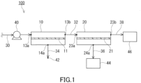
- the third chamber 23 has the inlet 23a and the outlet 23b.
- the fourth chamber 24 has the outlet 24a.
- the inlet 23a of the third chamber 23 is an opening for providing the first non-permeated gas 81 to the second separation membrane unit 20.
- the outlet 24a of the fourth chamber 24 is an opening for discharging, from the second separation membrane unit 20, a second permeated gas 90 obtained by allowing the first non-permeated gas 81 to permeate through the second separation membrane 21.
- the outlet 23b of the third chamber 23 is an opening for discharging, from the second separation membrane unit 20, the first non-permeated gas 81 (a second non-permeated gas 91) not having permeated through the second separation membrane 21.
- the inlet 23a, the outlet 23b, and the outlet 24a are formed, for example, in wall surfaces of the tank 22.
- a concentration of the gas A in the first non-permeated gas 81 gradually increases from the inlet 23a toward the outlet 23b in the third chamber 23.
- a content of the gas A in the first non-permeated gas 81 (the second non-permeated gas 91) processed in the third chamber 23 is, for example, but not particularly limited to, 70 vol% or more, preferably 80 vol% or more, more preferably 90 vol% or more, and still more preferably 95 vol% or more.
- the content of the gas A in the second non-permeated gas 91 is preferably 70 vol% or more.
- the second non-permeated gas 91 is discharged to the outside of the second separation membrane unit 20 via the outlet 23b.
- the second non-permeated gas 91 is delivered to the second recovery portion 46 via the second recovery passage 38.
- the membrane area M1 of the first separation membrane 11 and the membrane area M2 of the second separation membrane 21 satisfy a relational expression (1) below.
- a relational expression (2) or a relational expression (3) below may be satisfied instead of the relational expression (1) or together with the relational expression (1).
- T1 means a permeation rate of the gas A permeating through the first separation membrane 11
- T2 means a permeation rate of the gas B permeating through the second separation membrane 21.
- the first separation membrane unit 10 may be a spiral membrane element as shown in FIG. 5 .
- a first separation membrane unit 15 of FIG. 5 includes a central tube 16 and a laminate 17.
- the laminate 17 includes the first separation membrane 11.
- Calculation Example 4 was simulated in the same manner as in Calculation Example 1, except that it was assumed to use the carbon dioxide permeable membrane as the first separation membrane and to use the hydrogen permeable membrane as the second separation membrane.
- the gas separation system according to the assumption of Calculation Example 4 may be referred to as model 3-1.
- the membrane areas of the separation membranes required to separate the gas mixture by using the gas separation system, the purity of hydrogen (the content of H 2 in the second permeated gas), and the recovery rate of hydrogen (the ratio of the weight of H 2 in the second permeated gas with respect to the weight of H 2 in the gas mixture) were calculated. Table 1 shows the results.
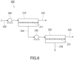
- the first recovery passage 332 is a passage connected to a permeated gas outlet of the separation membrane unit 310 and configured to recover the permeated gas from the separation membrane unit 310.
- the second recovery passage 334 is a passage connected to a non-permeated gas outlet of the separation membrane unit 310 and configured to recover the non-permeated gas from the separation membrane unit 310.
- Calculation Example 7 was simulated in the same manner as in Calculation Example 3, except that it was assumed to use the carbon dioxide permeable membrane as the first separation membrane 211, to use the carbon dioxide permeable membrane as the second separation membrane 221, and to recover the first non-permeated gas and the second permeated gas.
- the gas separation system according to the assumption of Calculation Example 7 may be referred to as model 5.
Landscapes
- Chemical & Material Sciences (AREA)
- Chemical Kinetics & Catalysis (AREA)
- Engineering & Computer Science (AREA)
- Inorganic Chemistry (AREA)
- Organic Chemistry (AREA)
- Analytical Chemistry (AREA)
- General Chemical & Material Sciences (AREA)
- Oil, Petroleum & Natural Gas (AREA)
- Combustion & Propulsion (AREA)
- Manufacturing & Machinery (AREA)
- Separation Using Semi-Permeable Membranes (AREA)
Applications Claiming Priority (2)
| Application Number | Priority Date | Filing Date | Title |
|---|---|---|---|
| JP2021136963 | 2021-08-25 | ||
| PCT/JP2022/029554 WO2023026783A1 (ja) | 2021-08-25 | 2022-08-01 | ガス分離システム及び混合ガスの分離方法 |
Publications (2)
| Publication Number | Publication Date |
|---|---|
| EP4393571A1 true EP4393571A1 (de) | 2024-07-03 |
| EP4393571A4 EP4393571A4 (de) | 2026-02-25 |
Family
ID=85323080
Family Applications (1)
| Application Number | Title | Priority Date | Filing Date |
|---|---|---|---|
| EP22861074.7A Pending EP4393571A4 (de) | 2021-08-25 | 2022-08-01 | Gastrennungssystem und verfahren zur trennung von mischgas |
Country Status (5)
| Country | Link |
|---|---|
| US (1) | US20240399296A1 (de) |
| EP (1) | EP4393571A4 (de) |
| JP (1) | JPWO2023026783A1 (de) |
| CN (1) | CN117794631A (de) |
| WO (1) | WO2023026783A1 (de) |
Families Citing this family (1)
| Publication number | Priority date | Publication date | Assignee | Title |
|---|---|---|---|---|
| CN116286107A (zh) * | 2023-03-27 | 2023-06-23 | 大连理工大学 | 一种应用于合成气的多级膜分离碳捕集工艺 |
Family Cites Families (11)
| Publication number | Priority date | Publication date | Assignee | Title |
|---|---|---|---|---|
| US5482539A (en) * | 1993-09-22 | 1996-01-09 | Enerfex, Inc. | Multiple stage semi-permeable membrane process and apparatus for gas separation |
| EP2141119B1 (de) * | 2007-03-29 | 2014-01-22 | Nippon Oil Corporation | Verfahren zur erzeugung von wasserstoff und rückgewinnung von kohlendioxid und vorrichtung dafür |
| JP5124158B2 (ja) * | 2007-04-13 | 2013-01-23 | 株式会社ノリタケカンパニーリミテド | メタン濃縮装置およびメタン濃縮方法 |
| JP5039471B2 (ja) * | 2007-07-27 | 2012-10-03 | Jx日鉱日石エネルギー株式会社 | 水素製造および二酸化炭素回収方法ならびに装置 |
| JP2013255898A (ja) * | 2012-06-13 | 2013-12-26 | Mitsubishi Electric Corp | ガス回収装置およびガス回収方法 |
| JP6553739B2 (ja) * | 2015-11-16 | 2019-07-31 | 株式会社ルネッサンス・エナジー・リサーチ | ガス回収装置、ガス回収方法、及び、半導体洗浄システム |
| WO2017206069A1 (en) * | 2016-05-31 | 2017-12-07 | Evonik Specialty Chemicals (Shanghai) Co., Ltd. | Process and apparatus for separating gases |
| US10239015B2 (en) * | 2016-11-22 | 2019-03-26 | Korea Institute Of Energy Research | Apparatus and method for separating carbon dioxide with self recycle loop |
| JP2018162184A (ja) | 2017-03-24 | 2018-10-18 | 三菱重工業株式会社 | ガス製造システム及びガス製造方法 |
| EP3695897A1 (de) * | 2019-02-12 | 2020-08-19 | Haffmans B.V. | System und verfahren zum trennen eines gasgemisches |
| US11911725B2 (en) * | 2019-03-26 | 2024-02-27 | Nitto Denko Corporation | Separation membrane |
-
2022
- 2022-08-01 EP EP22861074.7A patent/EP4393571A4/de active Pending
- 2022-08-01 WO PCT/JP2022/029554 patent/WO2023026783A1/ja not_active Ceased
- 2022-08-01 US US18/686,502 patent/US20240399296A1/en active Pending
- 2022-08-01 JP JP2023543771A patent/JPWO2023026783A1/ja active Pending
- 2022-08-01 CN CN202280054916.8A patent/CN117794631A/zh active Pending
Also Published As
| Publication number | Publication date |
|---|---|
| JPWO2023026783A1 (de) | 2023-03-02 |
| EP4393571A4 (de) | 2026-02-25 |
| WO2023026783A1 (ja) | 2023-03-02 |
| CN117794631A (zh) | 2024-03-29 |
| US20240399296A1 (en) | 2024-12-05 |
Similar Documents
| Publication | Publication Date | Title |
|---|---|---|
| US12076691B2 (en) | Apparatus and method for concentrating hydrogen isotopes | |
| EP4194076A1 (de) | Gastrennungssystem und verfahren zur trennung von mischgas | |
| US9186622B1 (en) | Device for separation of oxygen and nitrogen | |
| JP6774966B2 (ja) | アルカン類からのアルケン類の分離のための薄膜複合膜 | |
| EP4393571A1 (de) | Gastrennungssystem und verfahren zur trennung von mischgas | |
| JP2019526446A5 (de) | ||
| Feng et al. | Air separation by integrally asymmetric hollow‐fiber membranes | |
| Itoh et al. | Deposition of palladium inside straight mesopores of anodic alumina tube and its hydrogen permeability | |
| CN107803117B (zh) | 一种高稳定性介孔聚合物限域的离子液体支撑液膜及其制备方法和应用 | |
| EP3572141B1 (de) | Gastrennmembranelement, gastrennmembranmodul und gastrennvorrichtung | |
| EP3632527A1 (de) | Gastrennmembran, gastrennmembranelement, gastrenner und gastrennverfahren | |
| EP4681801A1 (de) | Gastrennungssystem und mischgastrennungsverfahren | |
| EP4670822A1 (de) | Gastrennungssystem und verfahren zur trennung von mischgas | |
| Li et al. | Repair of a Pd/α-Al2O3 composite membrane containing defects | |
| JP2014226650A (ja) | ガス分離膜の製造方法 | |
| JP2021100756A (ja) | 水素排出膜 | |
| EP4112157B1 (de) | Zusammensetzung einer ionischen flüssigkeit für eine kohlendioxid-trennmembran, kohlendioxid-trennmembran, die diese zusammensetzung hält, und kohlendioxid-konzentrationsvorrichtung, die mit dieser kohlendioxid-trennmembran versehen ist | |
| EP4306205A1 (de) | Spiralförmiges membranelement und membrantrennsystem | |
| US20050252856A1 (en) | Concentration of hydrogen peroxide | |
| WO2025063216A1 (ja) | ガス分離システム及び混合ガスの分離方法 | |
| JP2024118353A (ja) | 供給方法および供給装置 | |
| CN106654296B (zh) | 一种憎水透氧质子交换膜燃料电池阴极的制备方法 | |
| JP2020017374A (ja) | 基材処理装置および基材処理方法 | |
| Mercea et al. | Gas separation through a high-flux asymmetric polymer membrane metallized with palladium | |
| JP2023030786A (ja) | 二酸化炭素分離膜用イオン液体組成物、及び該組成物を保持した二酸化炭素分離膜、並びに該二酸化炭素分離膜を備えた二酸化炭素の濃縮装置 |
Legal Events
| Date | Code | Title | Description |
|---|---|---|---|
| STAA | Information on the status of an ep patent application or granted ep patent |
Free format text: STATUS: THE INTERNATIONAL PUBLICATION HAS BEEN MADE |
|
| PUAI | Public reference made under article 153(3) epc to a published international application that has entered the european phase |
Free format text: ORIGINAL CODE: 0009012 |
|
| STAA | Information on the status of an ep patent application or granted ep patent |
Free format text: STATUS: REQUEST FOR EXAMINATION WAS MADE |
|
| 17P | Request for examination filed |
Effective date: 20240306 |
|
| AK | Designated contracting states |
Kind code of ref document: A1 Designated state(s): AL AT BE BG CH CY CZ DE DK EE ES FI FR GB GR HR HU IE IS IT LI LT LU LV MC MK MT NL NO PL PT RO RS SE SI SK SM TR |
|
| DAV | Request for validation of the european patent (deleted) | ||
| DAX | Request for extension of the european patent (deleted) | ||
| A4 | Supplementary search report drawn up and despatched |
Effective date: 20260121 |
|
| RIC1 | Information provided on ipc code assigned before grant |
Ipc: B01D 69/00 20060101AFI20260116BHEP Ipc: B01D 71/52 20060101ALI20260116BHEP Ipc: B01D 71/56 20060101ALI20260116BHEP Ipc: B01D 53/22 20060101ALI20260116BHEP |