EP4392743B1 - Verfahren zur befestigung eines gehäuses für ein messgerät der prozess- oder automatisierungstechnik an einer wandung - Google Patents
Verfahren zur befestigung eines gehäuses für ein messgerät der prozess- oder automatisierungstechnik an einer wandung Download PDFInfo
- Publication number
- EP4392743B1 EP4392743B1 EP22768321.6A EP22768321A EP4392743B1 EP 4392743 B1 EP4392743 B1 EP 4392743B1 EP 22768321 A EP22768321 A EP 22768321A EP 4392743 B1 EP4392743 B1 EP 4392743B1
- Authority
- EP
- European Patent Office
- Prior art keywords
- housing
- wall
- measuring device
- recesses
- screw
- Prior art date
- Legal status (The legal status is an assumption and is not a legal conclusion. Google has not performed a legal analysis and makes no representation as to the accuracy of the status listed.)
- Active
Links
Images
Classifications
-
- G—PHYSICS
- G01—MEASURING; TESTING
- G01D—MEASURING NOT SPECIALLY ADAPTED FOR A SPECIFIC VARIABLE; ARRANGEMENTS FOR MEASURING TWO OR MORE VARIABLES NOT COVERED IN A SINGLE OTHER SUBCLASS; TARIFF METERING APPARATUS; MEASURING OR TESTING NOT OTHERWISE PROVIDED FOR
- G01D11/00—Component parts of measuring arrangements not specially adapted for a specific variable
- G01D11/30—Supports specially adapted for an instrument; Supports specially adapted for a set of instruments
-
- F—MECHANICAL ENGINEERING; LIGHTING; HEATING; WEAPONS; BLASTING
- F16—ENGINEERING ELEMENTS AND UNITS; GENERAL MEASURES FOR PRODUCING AND MAINTAINING EFFECTIVE FUNCTIONING OF MACHINES OR INSTALLATIONS; THERMAL INSULATION IN GENERAL
- F16B—DEVICES FOR FASTENING OR SECURING CONSTRUCTIONAL ELEMENTS OR MACHINE PARTS TOGETHER, e.g. NAILS, BOLTS, CIRCLIPS, CLAMPS, CLIPS OR WEDGES; JOINTS OR JOINTING
- F16B5/00—Joining sheets or plates, e.g. panels, to one another or to strips or bars parallel to them
- F16B5/02—Joining sheets or plates, e.g. panels, to one another or to strips or bars parallel to them by means of fastening members using screw-thread
-
- F—MECHANICAL ENGINEERING; LIGHTING; HEATING; WEAPONS; BLASTING
- F16—ENGINEERING ELEMENTS AND UNITS; GENERAL MEASURES FOR PRODUCING AND MAINTAINING EFFECTIVE FUNCTIONING OF MACHINES OR INSTALLATIONS; THERMAL INSULATION IN GENERAL
- F16B—DEVICES FOR FASTENING OR SECURING CONSTRUCTIONAL ELEMENTS OR MACHINE PARTS TOGETHER, e.g. NAILS, BOLTS, CIRCLIPS, CLAMPS, CLIPS OR WEDGES; JOINTS OR JOINTING
- F16B23/00—Specially shaped nuts or heads of bolts or screws for rotations by a tool
- F16B23/0007—Specially shaped nuts or heads of bolts or screws for rotations by a tool characterised by the shape of the recess or the protrusion engaging the tool
- F16B23/0038—Specially shaped nuts or heads of bolts or screws for rotations by a tool characterised by the shape of the recess or the protrusion engaging the tool substantially prismatic with up to six edges, e.g. triangular, square, pentagonal, Allen-type cross-sections
Definitions
- the invention relates to a method for fastening a housing for a measuring device in process or automation technology to a wall.
- Pressure measuring devices are often used in automation technology, particularly in pneumatic applications. These measuring devices, like a variety of other sensors that are used to monitor a medium or the properties of a medium, such as the pressure or temperature of a liquid or gas, usually consist of a lower part known as the process connection and a housing attached to it, which serves, among other things, to protect the sensor and the associated electronics.
- the process connection connects the sensor element to a container or pipe carrying the medium and usually contains the sensor element itself.
- the measuring device is usually mounted on or at the container or pipe containing the medium to be measured, in such a way that the mechanical connection is established solely by the process connection, which is usually screwed onto the connection piece of the pipe or container.
- the process connection must therefore have the appropriate mechanical stability to ensure a permanent connection.
- Pressure measuring devices in particular have special requirements for mechanical stability. For this reason, the process connection is often manufactured by machining a stainless steel workpiece.
- a pressure measuring device which is suitable for wall and mounting rail mounting by means of a base-like process connection block.
- the process connection block disclosed therein has horizontal and vertical through holes through which appropriately long screws can be passed in order to mount the process connection block and thus the entire pressure measuring device on a rear wall or on a surface.
- DE 20 2020 103546 U1 shows another known housing for an instrument, which is attached to a wall by means of horizontal holes.
- the object of the invention is to attach a measuring device of the aforementioned type to a wall in a simple manner without horizontal drilling.
- the starting point of the method according to the invention is, on the one hand, that the housing of the measuring device has a quasi-flat back, i.e. has at least three attachment points with which it should be placed directly on the wall, and on the front a display for displaying measurement and parameter data, possibly with various operating elements, is arranged. Furthermore, the back of the housing has at least two keyhole-like recesses with a wide and a narrow area. In addition, one of the side surfaces and/or the top and/or the bottom of the housing - i.e. not the front - has at least two holes running diagonally through the housing, the ends of which meet the keyhole-like recesses.
- the measuring device housing itself is firmly and securely attached to the wall using this method, as the screw shafts are located in the narrow area of the recesses due to the keyhole-like contours and the downward sliding or twisting of the measuring device housing, which already ensures horizontal fixation.
- An absolutely stable assembly is then achieved by firmly tightening the screws, which is possible using the hexagon wrench with a ball head despite the angled engagement of the ball head in the hexagon socket of the screw head.
- the front of the measuring device housing is completely unaffected and can accommodate a display over the entire surface.
- an advantageous further development provides that the inside of the back of the housing in the area of the transition between the wide and the narrow area of the at least two keyhole-like recesses has a brake wedge-like thickening over which the screw heads are guided while the measuring device housing is pushed downwards. This ensures that the measuring device housing is not only fixed in the axial direction by the tightened screws, but also in the radial direction, because the screw head is prevented from being displaced by the brake wedge-like thickening and thus any displacement of the housing resulting from friction can be prevented even when the screws are tightened.
- the effect could also be achieved by means of an inclined plane over which the screw heads are pushed while being pushed downwards or twisted. When they reach the end of the inclined plane, the screw heads then snap into place and the inclined plane acts like a barb.
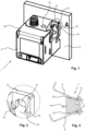
- Figure 1 shows a measuring device 1 for process or automation technology, fixed to a wall 2, in this case a pressure measuring device for measuring pneumatic pressures.
- the measuring device 1 has a cube-shaped housing 10, with at least one pressure connection for a pneumatic line located on the underside (and therefore not shown) and a plug connection visible on the top for passing on an electrical measurement signal converted from the measured pressure to a higher-level control unit, e.g. a PLC.
- the housing shape is not limited to a cube-shaped shape, however. All shapes are conceivable in which the measuring device 1, as in Fig. 1 shown, with the housing back 11 mounted on the wall 2.
- the housing 11 is shown partially cut open in the upper right corner.
- this measuring device 1 is that the front is completely filled with a display 3, whereby the term display does not only refer to the display unit itself, but also to the associated control buttons and the LED indicators shown on the two upper corners.
- the resulting problem is that the screws required to fix the measuring device 1 to the wall 2 cannot simply be passed through the measuring device housing 11 from the front.
- at least two obliquely running holes 13 are therefore provided, of which the opening of one of these holes 13 can be seen on the top.
- the housing back 11 has at least two keyhole-like recesses 12 with a wide and a narrow area. The narrow area is located at the top and its width corresponds essentially to the diameter of the hole 6, while the wide area is arranged below the narrow area and its width must correspond at least to the diameter of the screw head.
- the measuring device housing 10 is now placed on the wall 2 so that the screw heads of the screws 4 in the wall are each guided through the wide areas of the at least two keyhole-like recesses 12.
- the entire measuring device housing 11 is now pushed downwards so that the screw shafts of the screws 4 are each located in the narrow areas of the keyhole-like recesses 12.
- Fig. 1 This exact moment is shown during the assembly process, whereby, as mentioned, screws 4 have been omitted for better illustration.
- the screw shafts can also be moved into the narrow areas of the keyhole-like recesses 12 by rotating the housing 1 by a few degrees.
- the holes 13 on the surface of the housing 11 can be closed with a small cover.
- connection between the measuring device 1 and the wall 2 can be further improved by providing the inside of the housing rear 11 in the area of the transition between the wide and the narrow area of the keyhole-like recesses 12 with a brake wedge-like thickening 14, over which the screw heads are guided while the measuring device housing 11 is pushed downwards.
- Figure 2 which is an enlarged view of the area of the keyhole-like recesses 12 of Fig. 1 , two of these brake wedge-like thickenings 14 can be seen.
- the fully assembled measuring device 1 can no longer be moved so easily on the wall 2, which could happen, for example, when connecting the pneumatic pressure line.
- the screws 4 would have to be unscrewed far enough that their screw heads can be guided over the brake wedge-like thickenings 14, which requires a conscious or deliberate process and cannot be achieved by simply loosening the screws 4.
Landscapes
- Engineering & Computer Science (AREA)
- General Engineering & Computer Science (AREA)
- Mechanical Engineering (AREA)
- Physics & Mathematics (AREA)
- General Physics & Mathematics (AREA)
- Measuring Fluid Pressure (AREA)
- A Measuring Device Byusing Mechanical Method (AREA)
Description
- Die Erfindung betrifft ein Verfahren zur Befestigung eines Gehäuses für ein Messgerät der Prozess- oder Automatisierungstechnik an einer Wandung.
- In der Automatisierungstechnik, insbesondere bei Pneumatikapplikationen, werden häufig Druckmessgeräte eingesetzt. Diese Messgeräte wie eine Vielzahl anderer Sensoren, die zur Überwachung eines Mediums bzw. der Eigenschaft eines Mediums, wie z. B. des Druckes, Temperatur einer Flüssigkeit oder eines Gases, dienen, bestehen meist aus einem als Prozessanschluss bezeichneten Unterteil und einem darauf aufgesetzten Gehäuse, das u. a. zum Schutz des Sensors und der dazu gehörenden Elektronik dient. Der Prozessanschluss stellt die Verbindung des Sensorelements mit einem das Medium führenden Behälter oder Rohr her und beinhaltet meist das Sensorelement selbst.
- Meist erfolgt die Montage des Messgeräts auf oder an dem Behälter bzw. Rohr, worin sich das zu messende Medium befindet, in der Form, dass die mechanische Verbindung allein durch den üblicherweise auf dem Anschlussstutzen des Rohrs bzw. Behälters aufgeschraubten Prozessanschluss hergestellt wird. Der Prozessanschluss muss daher über eine entsprechende mechanische Stabilität verfügen, um eine dauerhafte Verbindung zu gewährleisten. Insbesondere bei Druckmessgeräten werden an die mechanische Stabilität besondere Anforderungen gestellt. Aus diesem Grund wird der Prozessanschluss häufig durch Zerspanung eines Edelstahlwerkstücks hergestellt.
- Andererseits gibt es die Möglichkeit, Sensoren an einer Wandung oder auf einer Tragschiene, bspw. einer Hutschiene, zu befestigen. Die mechanische Verbindung wird in diesen Fällen nicht oder nicht ausschließlich über den Prozessanschluss hergestellt. Hierfür gibt es eine Vielzahl an Möglichkeiten, die jedoch in den meisten Fällen ein oder mehrere Zusatzteile, wie z. B. Schellen, Klammern, Wandhalterungen o. dgl. erforderlich machen.
- Aus der
DE 102008026020 B4 ist ein Druckmessgerät bekannt, das mittels eines sockelartig ausgebildeten Prozessanschlussblocks zur Wand- und Tragschienenmontage geeignet ist. Der dort offenbarte Prozessanschlussblock weist horizontale und vertikale Durchgangsbohrungen auf, durch die entsprechend lange Schrauben geführt werden können, um den Prozessanschlussblock und damit das gesamte Druckmessgerät an eine rückwärtige Wandung oder auf einem Untergrund montieren zu können. DieDE 20 2020 103546 U1 zeigt ein weiteres bekanntes Gehäuse für ein Instrument, welches mittels horizontaler Bohrungen an einer Wandung angebracht wird. - Eine derartige Wandmontage ist jedoch nicht möglich, wenn aus verschiedenen Gründen keine horizontalen Bohrungen möglich sind. Ein Grund dafür könnte bspw. sein, dass es sich um ein kompaktes, quaderförmiges Messgerätegehäuse handelt, bei dem die Vorderseite vollständig von einem Display ausgefüllt ist und sich dadurch kein Platz für derartige Bohrungen ergibt. Ein weiterer Grund könnte sein, dass aus ästhetischen Gründen auf sichtbare Bohrungen bzw. Schraubenköpfe an der Vorderseite verzichtet werden soll.
- Aufgabe der Erfindung ist es, auf einfache Weise ein Messgerät der vorgenannten Art ohne horizontale Bohrungen an einer Wandung zu befestigen.
- Die Aufgabe wird durch ein Verfahren mit den Merkmalen des Anspruchs 1 gelöst. Vorteilhafte Ausgestaltungen der Erfindung sind in den Unteransprüchen angegeben. Ausgangspunkt des erfindungsgemäßen Verfahrens ist zum einen, dass das Gehäuse des Messgeräts eine quasi-plane Rückseite aufweist, d.h. über wenigstens drei Anschlagpunkten verfügt, mit der es unmittelbar an der Wandung zur Anlage kommen soll und auf der Vorderseite ein Display zur Anzeige von Mess- und Parameterdaten, ggf. mit diversen Bedienelementen, angeordnet ist. Weiterhin weist die Gehäuserückseite wenigstens zwei Schlüsselloch-ähnliche Aussparungen mit einem breiten und einem schmalen Bereich auf. Außerdem weist eine der Seitenflächen und/oder die Oberseite und/oder die Unterseite des Gehäuses - also nicht die Vorderseite - wenigstens zwei schräg durch das Gehäuse verlaufende Bohrungen auf, die mit ihrem Ende auf die Schlüsselloch-ähnlichen Aussparungen stoßen.
- Das erfindungsgemäße Verfahren ist dann durch folgende Verfahrensschritte gekennzeichnet:
- Bohren von wenigstens zwei Löchern in die Wand entsprechend des Lochbildes auf der Gehäuserückseite;
- Einschrauben von jeweils einer Innensechskant-Schraube in diese Löcher, mit einem Abstand zwischen Wand und Schraubenkopf, der wenigstens der Dicke der Gehäuserückseite entspricht;
- Aufsetzen des Messgerätegehäuses auf die Wandung, derart, dass die Schraubenköpfe der in der Wand befindlichen Schrauben jeweils durch die breiten Bereiche der wenigstens zwei Schlüsselloch-ähnlichen Aussparungen in der Gehäuserückseite geführt werden;
- Nach-unten-Schieben oder Um-die-eigene-Achse-Verdrehen des Messgerätegehäuses, so dass sich die Schraubenschäfte der wenigstens zwei Schrauben jeweils im schmalen Bereich der wenigstens zwei Schlüsselloch-ähnlichen Aussparungen befinden;
- Einführen eines Sechskantschlüssels mit Kugelkopf in die wenigstens zwei schräg verlaufenden Bohrungen, derart, dass der Kugelkopf in den Innensechskant des Schraubenkopfes eingreift und die jeweilige Schraube angezogen wird.
- Das Messgerätegehäuse selbst ist durch dieses Verfahren fest und sicher an der Wandung befestigt, da zum einen die durch die Aussparungen mit ihrer Schlüsselloch-ähnlichen Kontur und das Nach-unten-Schieben bzw. Verdrehen des Messgerätegehäuses die Schraubenschäfte sich jeweils im schmalen Bereich dieser Aussparungen befinden, wodurch bereits eine horizontale Fixierung erreicht ist. Eine absolut stabile Montage wird dann dadurch erreicht, dass die Schrauben fest angezogen werden, was mit Hilfe des Sechskantschlüssels mit Kugelkopf trotz des schrägen Eingreifens des Kugelkopfes in den Innensechskant des Schraubenkopfes möglich ist.
- Durch die schräg verlaufenden Bohrungen ist die Vorderseite des Messgerätegehäuses völlig unbeeinträchtigt und kann über die gesamte Fläche ein Display aufnehmen.
- Eine vorteilhafte Weiterbildung sieht vor, dass die Innenseite der Gehäuserückseite im Bereich des Übergangs zwischen dem breiten und dem schmalen Bereich der wenigstens zwei Schlüsselloch-ähnlichen Aussparungen jeweils eine Bremskeil-artige Verdickung aufweist, über die die Schraubenköpfe während des Nach-unten-schiebens des Messgerätegehäuses geführt werden. Dadurch wird erreicht, dass das Messgerätegehäuse durch die angezogenen Schrauben nicht nur in axialer Richtung fixiert ist, sondern auch in radialer, weil der Schraubenkopf durch die bremskeil-artige Verdickung an einer Verschiebbarkeit gehindert wird und sich dadurch auch während des Anziehens der Schrauben eine aus der Reibung resultierende Verschiebung des Gehäuses verhindern lässt.
- Alternativ zu einer bremskeil-artigen Verdickung könnte der Effekt auch durch eine schräge Ebene erreicht werden, über die die Schraubenköpfe während des Nach-unten-Schiebens bzw. Verdrehens zu schieben sind. Am Ende der schrägen Ebene angelangt rasten die Schraubenköpfe dann gewissermaßen ein und die schräge Ebene wirkt wie ein Widerhaken.
- Nachfolgend wird die Erfindung anhand von Ausführungsbeispielen unter Bezugnahme auf die Zeichnungen näher erläutert.
- Es zeigen schematisch:
- Figur 1
- ein an eine Wandung fixiertes Messgerät der Prozess- oder Automatisierungstechnik,
- Figur 2
- eine vergrößerte Darstellung eines Bereichs aus
Fig. 1 und - Figur 3
- Darstellung eines Zwischenschritts des erfindungsgemäßen Verfahrens.
- Bei der nachfolgenden Beschreibung der bevorzugten Ausführungsformen bezeichnen gleiche Bezugszeichen gleiche oder vergleichbare Komponenten.
-
Figur 1 zeigt ein an eine Wandung 2 fixiertes Messgerät 1 der Prozess- oder Automatisierungstechnik, vorliegend ein Druckmessgerät zu Erfassung von Pneumatikdrücken. Das Messgerät 1 hat ein würfelförmiges Gehäuse 10, mit wenigstens einem auf der Unterseite befindlichen (und deswegen nicht dargestellten) Druckanschluss für eine Pneumatikleitung und einem auf der Oberseite ersichtlichen Steckeranschluss zur Weitergabe eines aus dem gemessenen Druck umgewandelten elektrischen Messsignals an eine übergeordnete Steuereinheit, bspw. eine SPS. Die Gehäuseform ist jedoch nicht auf eine würfelförmige Gestalt beschränkt. Denkbar sind alle Formen, bei denen das Messgerät 1, wie inFig. 1 gezeigt, mit der Gehäuserückseite 11 an der Wandung 2 montiert werden kann. An der oberen rechten Ecke ist das Gehäuse 11 teilweise aufgeschnitten dargestellt. - Das Besondere dieses Messgeräts 1 ist, dass die Vorderseite komplett von einem Display 3 ausgefüllt ist, wobei unter dem Begriff Display nicht nur die reine Anzeigeeinheit zu verstehen ist, sondern auch die dazugehörigen Bedientasten sowie die dargestellten LED-Indikatoren an den beiden oberen Ecken. Das daraus entstehende Problem ist, dass die zur Fixierung des Messgeräts 1 an der Wandung 2 notwendigen Schauben nicht einfach von vorn durch das Messgerätegehäuse 11 durchgeführt werden können. Erfindungsgemäß sind deshalb wenigstens zwei schräg verlaufende Bohrungen 13 vorgesehen, wovon die Öffnung einer dieser Bohrungen 13 auf der Oberseite zu erkennen ist.
- Für die Montage des Messgeräts 1 an der Wandung 2 ist es zunächst erforderlich, dass in die Wandung 2 wenigstens zwei Löcher 6 entsprechend des Lochbildes auf der Gehäuserückseite 11 gebohrt werden. In diese Löcher 6 wird jeweils eine Innensechskant-Schraube 4 eingeschraubt, wobei der Abstand zwischen Wand 2 und Schraubenkopf wenigstens der Dicke der Gehäuserückseite 11 entsprechen muss. In
Fig. 1 ist lediglich ein Loch 6 dargestellt, ohne Schraube 4. Die Gehäuserückseite 11 weist wenigstens zwei Schlüsselloch-ähnliche Aussparungen 12 mit einem breiten und einem schmalen Bereich auf. Der schmale Bereich befindet sich oben und entspricht von seiner Breite im Wesentlichen dem Durchmesser des Loches 6, während der breite Bereich unterhalb des schmalen Bereichs angeordnet ist und von seiner Breite zumindest dem Durchmesser des Schraubenkopfes entsprechen muss. - Das Messgerätegehäuse 10 wird nun auf die Wandung 2 aufgesetzt, so dass die Schraubenköpfe der in der Wand befindlichen Schrauben 4 jeweils durch die breiten Bereiche der wenigstens zwei Schlüsselloch-ähnlichen Aussparungen 12 geführt werden. Nun wird das gesamte Messgerätegehäuse 11 nach unten geschoben, so dass sich die Schraubenschäfte der Schrauben 4 jeweils in den schmalen Bereichen der Schlüsselloch-ähnlichen Aussparungen 12 befinden. In
Fig. 1 ist exakt dieser Moment während des Montageverfahrens abgebildet, wobei wie erwähnt zur besseren Darstellung auf die Schrauben 4 verzichtet wurde. - Alternativ zum Nach-unten-schieben ließen sich die Schraubenschäfte auch durch eine Drehbewegung des Gehäuses 1 um wenige Grad in die schmalen Bereiche der Schlüsselloch-ähnlichen Aussparungen 12 hineinbewegen.
- In
Figur 3 ist nun sehr schematisch der nächste Verfahrensschritt abgebildet, bei dem jeweils ein Sechskantschlüssel 5 mit Kugelkopf in die zwei schräg verlaufenden Bohrungen 13 eingeführt wurden. Der Kugelkopf des Sechskantschlüssels 5 greift dabei in den Innensechskant des Schraubenkopfes ein, so dass die jeweilige Schraube 4 angezogen werden kann. Damit ist das Messgerät 1 an der Wandung montiert. - Um ein Eindringen von Staub- und Dreckpartikeln zu verhindern, können die Bohrungen 13 an der Oberfläche des Gehäuses 11 mit einem kleinen Deckel verschlossen werden.
- Die Verbindung zwischen Messgerät 1 und Wandung 2 kann weiter verbessert werden, indem die Innenseite der Gehäuserückseite 11 im Bereich des Übergangs zwischen dem breiten und dem schmalen Bereich der Schlüsselloch-ähnlichen Aussparungen 12 jeweils eine Bremskeil-artige Verdickung 14 aufweist, über die die Schraubenköpfe während des Nach-unten-schiebens des Messgerätegehäuses 11 geführt werden. In
Figur 2 , die eine vergrößerte Ansicht des Bereichs der Schlüsselloch-ähnlichen Aussparungen 12 ausFig. 1 darstellt, sind zwei dieser Bremskeil-artigen Verdickungen 14 zu erkennen. Das fertig montierte Messgerät 1 lässt sich mit dieser Maßnahme nicht mehr so einfach an der Wandung 2 verschieben, was bspw. während des Anschlusses der Pneumatikdruckleitung geschehen könnte. Zur Demontage müssten die Schrauben 4 derart weit herausgeschraubt werden, dass deren Schraubenköpfe über die Bremskeil-artigen Verdickungen 14 geführt werden können, was einen bewussten bzw. gewollten Vorgang voraussetzt und nicht durch ein selbstständiges leichtes Lösen der Schrauben 4 erreicht werden kann. - Der gleiche Effekt ließe sich auch erzielen, wenn statt der bremskeil-artigen Verdickungen eine schräge Ebene vorgesehen ist, über die die Schraubenköpfe während des Nach-unten-Schiebens bzw. Verdrehens zu schieben sind. Am Ende der schrägen Ebene angelangt rasten die Schraubenköpfe dann gewissermaßen ein und die schräge Ebene wirkt ebenfalls wie ein Widerhaken.
- Denkbar, von der Erfindung jedoch nicht mit umfasst, ist auch, deutlich kürzere Schrauben 4 als in
Fig. 3 darstellt zu verwenden und statt der schräg verlaufenden Bohrungen 13 Ausnehmungen an der Stelle des Messgerätegehäuses 10 vorzusehen, wo sich die Aussparungen zum Durchführen der Schrauben durch die Gehäuserückseite befinden. Durch diese Ausnehmungen hindurch könnten dann ebenfalls die Sechskantschlüssel mit Kugelkopf eingeführt und die Schrauben angezogen werden. -
- 1
- Messgerät
- 2
- Wandung
- 3
- Display
- 4
- Schraube
- 5
- Sechskantschlüssel
- 6
- Loch
- 10
- Gehäuse des Messgeräts
- 11
- Rückseite des Gehäuses
- 12
- Schlüsselloch-ähnliche Aussparung
- 13
- Bohrung
- 14
- Bremskeil-artige Verdickung
Claims (3)
- Verfahren zur Befestigung eines Gehäuses (10) für ein Messgerät (1) der Prozess- oder Automatisierungstechnik an einer Wandung (2),wobei das Gehäuse (10) eine quasi-plane Rückseite (11) aufweist, mit der das Gehäuse unmittelbar an der Wandung (2) zur Anlage kommen soll und auf der Vorderseite ein Display (3) zur Anzeige von Mess- und Parameterdaten angeordnet ist,wobei die Gehäuserückseite (11) wenigstens zwei Schlüsselloch-ähnliche Aussparungen (12) mit einem breiten und einem schmalen Bereich aufweist, und wobei eine der Seitenflächen und/oder die Oberseite und/oder die Unterseite des Gehäuses wenigstens zwei schräg verlaufende Bohrungen (13) aufweisen, die mit ihrem Ende auf die Schlüsselloch-ähnlichen Aussparungen (12) stoßen,gekennzeichnet durch folgende Verfahrensschritte:- Bohren von wenigstens zwei Löchern (6) in die Wandung (2) entsprechend des Lochbildes auf der Gehäuserückseite (11);- Einschrauben von jeweils einer Innensechskant-Schraube (4) in diese Löcher (6), mit einem Abstand zwischen Wand und Schraubenkopf, der wenigstens der Dicke der Gehäuserückseite (11) entspricht;- Aufsetzen des Messgerätegehäuses (10) auf die Wandung (2), derart, dass die Schraubenköpfe der in der Wand befindlichen Schrauben (4) jeweils durch die breiten Bereiche der wenigstens zwei Schlüsselloch-ähnlichen Aussparungen (12) in der Gehäuserückseite (11) geführt werden;- Nach-unten-schieben oder Verdrehen des Messgerätegehäuses (11), so dass sich die Schraubenschäfte der wenigstens zwei Schrauben (4) jeweils im schmalen Bereich der wenigstens zwei Schlüsselloch-ähnlichen Aussparungen (12) befinden;- Einführen eines Sechskantschlüssels (5) mit Kugelkopf in die wenigstens zwei schräg verlaufenden Bohrungen (13), derart, dass der Kugelkopf in den Innensechskant des Schraubenkopfes eingreift und die jeweilige Schraube (4) angezogen wird.
- Verfahren nach Anspruch 1,
dadurch gekennzeichnet, dass die Innenseite der Gehäuserückseite (11) im Bereich des Übergangs zwischen dem breiten und dem schmalen Bereich der wenigstens zwei Schlüsselloch-ähnlichen Aussparungen (12) jeweils eine Bremskeil-artige Verdickung (14) aufweist, über die die Schraubenköpfe während des Nach-unten-schiebens des Messgerätegehäuses (10) geführt werden. - Verfahren nach Anspruch 1,
dadurch gekennzeichnet, dass die Innenseite der Gehäuserückseite (11) im Bereich des Übergangs zwischen dem breiten und dem schmalen Bereich der wenigstens zwei Schlüsselloch-ähnlichen Aussparungen (12) jeweils eine schräge Ebene aufweist, über die die Schraubenköpfe während des Nach-unten-schiebens des Messgerätegehäuses (10) geführt werden.
Applications Claiming Priority (2)
| Application Number | Priority Date | Filing Date | Title |
|---|---|---|---|
| DE102021122116.1A DE102021122116B4 (de) | 2021-08-26 | 2021-08-26 | Verfahren zur Befestigung eines Gehäuses für ein Messgerät der Prozess- oder Automatisierungstechnik an einer Wandung |
| PCT/EP2022/073099 WO2023025659A1 (de) | 2021-08-26 | 2022-08-18 | Verfahren zur befestigung eines gehäuses für ein messgerät der prozess- oder automatisierungstechnik an einer wandung |
Publications (2)
| Publication Number | Publication Date |
|---|---|
| EP4392743A1 EP4392743A1 (de) | 2024-07-03 |
| EP4392743B1 true EP4392743B1 (de) | 2024-11-06 |
Family
ID=83271577
Family Applications (1)
| Application Number | Title | Priority Date | Filing Date |
|---|---|---|---|
| EP22768321.6A Active EP4392743B1 (de) | 2021-08-26 | 2022-08-18 | Verfahren zur befestigung eines gehäuses für ein messgerät der prozess- oder automatisierungstechnik an einer wandung |
Country Status (3)
| Country | Link |
|---|---|
| EP (1) | EP4392743B1 (de) |
| DE (1) | DE102021122116B4 (de) |
| WO (1) | WO2023025659A1 (de) |
Families Citing this family (1)
| Publication number | Priority date | Publication date | Assignee | Title |
|---|---|---|---|---|
| DE102024113860A1 (de) * | 2024-05-17 | 2025-06-12 | Ifm Electronic Gmbh | Anordnung zur Befestigung eines Messgeräts der Prozess- oder Automatisierungstechnik an einer Wandung oder dergleichen |
Family Cites Families (6)
| Publication number | Priority date | Publication date | Assignee | Title |
|---|---|---|---|---|
| DE19905952C2 (de) * | 1999-02-12 | 2001-04-05 | Sew Eurodrive Gmbh & Co | Verteilerkasten |
| DE29919737U1 (de) | 1999-03-16 | 2000-01-20 | Rittal-Werk Rudolf Loh GmbH & Co. KG, 35745 Herborn | Bausatz für ein Gehäuse |
| DE102008026020B4 (de) | 2008-05-30 | 2013-04-11 | Ifm Electronic Gmbh | Druckmessgerät zur Differenzdruckmessung |
| US20130293388A1 (en) * | 2012-04-10 | 2013-11-07 | Daryl Ingalsbe | Cellular tank monitoring technology |
| DE202016102166U1 (de) * | 2016-04-25 | 2016-05-10 | Asm Automation Sensorik Messtechnik Gmbh | Sensorgehäuse |
| CN211904429U (zh) * | 2020-03-13 | 2020-11-10 | 上海凌源设备工程有限公司 | 一种光能数字仪表 |
-
2021
- 2021-08-26 DE DE102021122116.1A patent/DE102021122116B4/de active Active
-
2022
- 2022-08-18 WO PCT/EP2022/073099 patent/WO2023025659A1/de not_active Ceased
- 2022-08-18 EP EP22768321.6A patent/EP4392743B1/de active Active
Also Published As
| Publication number | Publication date |
|---|---|
| EP4392743A1 (de) | 2024-07-03 |
| WO2023025659A1 (de) | 2023-03-02 |
| DE102021122116B4 (de) | 2025-12-31 |
| DE102021122116A1 (de) | 2023-03-02 |
Similar Documents
| Publication | Publication Date | Title |
|---|---|---|
| EP0514668B1 (de) | Schrank | |
| EP3384567B1 (de) | Rahmengestell für eine schaltschrankanordnung | |
| EP3572605B1 (de) | Schaltschrankgehäuse mit einem über eine scharnieranordnung befestigten türelement | |
| DE4317599C2 (de) | Scharnieranordnung | |
| DE112010004991B4 (de) | Rahmenelemente und Aufbauten | |
| DE102007030439A1 (de) | Strömungssensor | |
| DE3132855C2 (de) | ||
| EP1849952A2 (de) | Montagesystem für Fenster und dergleichen | |
| DE102021122116B4 (de) | Verfahren zur Befestigung eines Gehäuses für ein Messgerät der Prozess- oder Automatisierungstechnik an einer Wandung | |
| CH658564A5 (de) | Bausatz zur erstellung von montageroesten fuer geraete und verwendung desselben. | |
| DE10066057A1 (de) | Tür, insbesondere Sicherheitstür | |
| DE3741684C2 (de) | ||
| CH680421A5 (de) | ||
| DE102021122008A1 (de) | Scharnier sowie Türanordnung und Verfahren zur Befestigung einer Tür | |
| DE2539363C2 (de) | Blendrahmenschenkel | |
| DE3422222A1 (de) | Gestell aus einem profilstab und daran mit einem verbinder angebrachter platte o. dgl. gestellteil | |
| DE4305681A1 (de) | Befestigungsanordnung für ein Gestell eines Tasteninstruments | |
| DE10113405A1 (de) | Vorrichtung zum Justieren und Fixieren eines Elementes zwischen zwei Bauteilen | |
| DE3420841A1 (de) | Verbindungsvorrichtung zur erstellung einer mehrdimensionalen konstruktion | |
| DE2555289B2 (de) | Vorrichtung zum aufhaengen von schiebetueren | |
| DE102024113860A1 (de) | Anordnung zur Befestigung eines Messgeräts der Prozess- oder Automatisierungstechnik an einer Wandung oder dergleichen | |
| DE7313052U (de) | Vorrichtung zum Verbinden von Anbaumöbeln | |
| DE10147988B4 (de) | Schaltschrank | |
| EP0708260B1 (de) | Befestigungs- und Verbindungsmittel | |
| DE10209083C2 (de) | Anordnung zur Festlegung eines Slotwinkels |
Legal Events
| Date | Code | Title | Description |
|---|---|---|---|
| STAA | Information on the status of an ep patent application or granted ep patent |
Free format text: STATUS: UNKNOWN |
|
| STAA | Information on the status of an ep patent application or granted ep patent |
Free format text: STATUS: THE INTERNATIONAL PUBLICATION HAS BEEN MADE |
|
| PUAI | Public reference made under article 153(3) epc to a published international application that has entered the european phase |
Free format text: ORIGINAL CODE: 0009012 |
|
| STAA | Information on the status of an ep patent application or granted ep patent |
Free format text: STATUS: REQUEST FOR EXAMINATION WAS MADE |
|
| 17P | Request for examination filed |
Effective date: 20240313 |
|
| AK | Designated contracting states |
Kind code of ref document: A1 Designated state(s): AL AT BE BG CH CY CZ DE DK EE ES FI FR GB GR HR HU IE IS IT LI LT LU LV MC MK MT NL NO PL PT RO RS SE SI SK SM TR |
|
| GRAP | Despatch of communication of intention to grant a patent |
Free format text: ORIGINAL CODE: EPIDOSNIGR1 |
|
| STAA | Information on the status of an ep patent application or granted ep patent |
Free format text: STATUS: GRANT OF PATENT IS INTENDED |
|
| GRAS | Grant fee paid |
Free format text: ORIGINAL CODE: EPIDOSNIGR3 |
|
| DAV | Request for validation of the european patent (deleted) | ||
| DAX | Request for extension of the european patent (deleted) | ||
| INTG | Intention to grant announced |
Effective date: 20240828 |
|
| GRAA | (expected) grant |
Free format text: ORIGINAL CODE: 0009210 |
|
| STAA | Information on the status of an ep patent application or granted ep patent |
Free format text: STATUS: THE PATENT HAS BEEN GRANTED |
|
| AK | Designated contracting states |
Kind code of ref document: B1 Designated state(s): AL AT BE BG CH CY CZ DE DK EE ES FI FR GB GR HR HU IE IS IT LI LT LU LV MC MK MT NL NO PL PT RO RS SE SI SK SM TR |
|
| REG | Reference to a national code |
Ref country code: GB Ref legal event code: FG4D Free format text: NOT ENGLISH |
|
| REG | Reference to a national code |
Ref country code: CH Ref legal event code: EP |
|
| REG | Reference to a national code |
Ref country code: DE Ref legal event code: R096 Ref document number: 502022002093 Country of ref document: DE |
|
| REG | Reference to a national code |
Ref country code: IE Ref legal event code: FG4D Free format text: LANGUAGE OF EP DOCUMENT: GERMAN |
|
| REG | Reference to a national code |
Ref country code: LT Ref legal event code: MG9D |
|
| REG | Reference to a national code |
Ref country code: NL Ref legal event code: MP Effective date: 20241106 |
|
| PG25 | Lapsed in a contracting state [announced via postgrant information from national office to epo] |
Ref country code: PT Free format text: LAPSE BECAUSE OF FAILURE TO SUBMIT A TRANSLATION OF THE DESCRIPTION OR TO PAY THE FEE WITHIN THE PRESCRIBED TIME-LIMIT Effective date: 20250306 Ref country code: HR Free format text: LAPSE BECAUSE OF FAILURE TO SUBMIT A TRANSLATION OF THE DESCRIPTION OR TO PAY THE FEE WITHIN THE PRESCRIBED TIME-LIMIT Effective date: 20241106 Ref country code: IS Free format text: LAPSE BECAUSE OF FAILURE TO SUBMIT A TRANSLATION OF THE DESCRIPTION OR TO PAY THE FEE WITHIN THE PRESCRIBED TIME-LIMIT Effective date: 20250306 |
|
| PG25 | Lapsed in a contracting state [announced via postgrant information from national office to epo] |
Ref country code: FI Free format text: LAPSE BECAUSE OF FAILURE TO SUBMIT A TRANSLATION OF THE DESCRIPTION OR TO PAY THE FEE WITHIN THE PRESCRIBED TIME-LIMIT Effective date: 20241106 Ref country code: NL Free format text: LAPSE BECAUSE OF FAILURE TO SUBMIT A TRANSLATION OF THE DESCRIPTION OR TO PAY THE FEE WITHIN THE PRESCRIBED TIME-LIMIT Effective date: 20241106 |
|
| PG25 | Lapsed in a contracting state [announced via postgrant information from national office to epo] |
Ref country code: BG Free format text: LAPSE BECAUSE OF FAILURE TO SUBMIT A TRANSLATION OF THE DESCRIPTION OR TO PAY THE FEE WITHIN THE PRESCRIBED TIME-LIMIT Effective date: 20241106 |
|
| PG25 | Lapsed in a contracting state [announced via postgrant information from national office to epo] |
Ref country code: ES Free format text: LAPSE BECAUSE OF FAILURE TO SUBMIT A TRANSLATION OF THE DESCRIPTION OR TO PAY THE FEE WITHIN THE PRESCRIBED TIME-LIMIT Effective date: 20241106 |
|
| PG25 | Lapsed in a contracting state [announced via postgrant information from national office to epo] |
Ref country code: NO Free format text: LAPSE BECAUSE OF FAILURE TO SUBMIT A TRANSLATION OF THE DESCRIPTION OR TO PAY THE FEE WITHIN THE PRESCRIBED TIME-LIMIT Effective date: 20250206 |
|
| PG25 | Lapsed in a contracting state [announced via postgrant information from national office to epo] |
Ref country code: LV Free format text: LAPSE BECAUSE OF FAILURE TO SUBMIT A TRANSLATION OF THE DESCRIPTION OR TO PAY THE FEE WITHIN THE PRESCRIBED TIME-LIMIT Effective date: 20241106 Ref country code: GR Free format text: LAPSE BECAUSE OF FAILURE TO SUBMIT A TRANSLATION OF THE DESCRIPTION OR TO PAY THE FEE WITHIN THE PRESCRIBED TIME-LIMIT Effective date: 20250207 |
|
| PG25 | Lapsed in a contracting state [announced via postgrant information from national office to epo] |
Ref country code: PL Free format text: LAPSE BECAUSE OF FAILURE TO SUBMIT A TRANSLATION OF THE DESCRIPTION OR TO PAY THE FEE WITHIN THE PRESCRIBED TIME-LIMIT Effective date: 20241106 |
|
| PG25 | Lapsed in a contracting state [announced via postgrant information from national office to epo] |
Ref country code: RS Free format text: LAPSE BECAUSE OF FAILURE TO SUBMIT A TRANSLATION OF THE DESCRIPTION OR TO PAY THE FEE WITHIN THE PRESCRIBED TIME-LIMIT Effective date: 20250206 |
|
| PG25 | Lapsed in a contracting state [announced via postgrant information from national office to epo] |
Ref country code: SM Free format text: LAPSE BECAUSE OF FAILURE TO SUBMIT A TRANSLATION OF THE DESCRIPTION OR TO PAY THE FEE WITHIN THE PRESCRIBED TIME-LIMIT Effective date: 20241106 |
|
| PG25 | Lapsed in a contracting state [announced via postgrant information from national office to epo] |
Ref country code: DK Free format text: LAPSE BECAUSE OF FAILURE TO SUBMIT A TRANSLATION OF THE DESCRIPTION OR TO PAY THE FEE WITHIN THE PRESCRIBED TIME-LIMIT Effective date: 20241106 |
|
| PG25 | Lapsed in a contracting state [announced via postgrant information from national office to epo] |
Ref country code: EE Free format text: LAPSE BECAUSE OF FAILURE TO SUBMIT A TRANSLATION OF THE DESCRIPTION OR TO PAY THE FEE WITHIN THE PRESCRIBED TIME-LIMIT Effective date: 20241106 |
|
| PG25 | Lapsed in a contracting state [announced via postgrant information from national office to epo] |
Ref country code: RO Free format text: LAPSE BECAUSE OF FAILURE TO SUBMIT A TRANSLATION OF THE DESCRIPTION OR TO PAY THE FEE WITHIN THE PRESCRIBED TIME-LIMIT Effective date: 20241106 |
|
| PG25 | Lapsed in a contracting state [announced via postgrant information from national office to epo] |
Ref country code: SK Free format text: LAPSE BECAUSE OF FAILURE TO SUBMIT A TRANSLATION OF THE DESCRIPTION OR TO PAY THE FEE WITHIN THE PRESCRIBED TIME-LIMIT Effective date: 20241106 |
|
| PG25 | Lapsed in a contracting state [announced via postgrant information from national office to epo] |
Ref country code: CZ Free format text: LAPSE BECAUSE OF FAILURE TO SUBMIT A TRANSLATION OF THE DESCRIPTION OR TO PAY THE FEE WITHIN THE PRESCRIBED TIME-LIMIT Effective date: 20241106 |
|
| PG25 | Lapsed in a contracting state [announced via postgrant information from national office to epo] |
Ref country code: IT Free format text: LAPSE BECAUSE OF FAILURE TO SUBMIT A TRANSLATION OF THE DESCRIPTION OR TO PAY THE FEE WITHIN THE PRESCRIBED TIME-LIMIT Effective date: 20241106 |
|
| REG | Reference to a national code |
Ref country code: DE Ref legal event code: R097 Ref document number: 502022002093 Country of ref document: DE |
|
| PG25 | Lapsed in a contracting state [announced via postgrant information from national office to epo] |
Ref country code: SE Free format text: LAPSE BECAUSE OF FAILURE TO SUBMIT A TRANSLATION OF THE DESCRIPTION OR TO PAY THE FEE WITHIN THE PRESCRIBED TIME-LIMIT Effective date: 20241106 |
|
| PLBE | No opposition filed within time limit |
Free format text: ORIGINAL CODE: 0009261 |
|
| STAA | Information on the status of an ep patent application or granted ep patent |
Free format text: STATUS: NO OPPOSITION FILED WITHIN TIME LIMIT |
|
| PGFP | Annual fee paid to national office [announced via postgrant information from national office to epo] |
Ref country code: DE Payment date: 20250819 Year of fee payment: 4 |
|
| 26N | No opposition filed |
Effective date: 20250807 |
|
| PGFP | Annual fee paid to national office [announced via postgrant information from national office to epo] |
Ref country code: AT Payment date: 20251020 Year of fee payment: 4 Ref country code: FR Payment date: 20250821 Year of fee payment: 4 |
|
| REG | Reference to a national code |
Ref country code: CH Ref legal event code: H13 Free format text: ST27 STATUS EVENT CODE: U-0-0-H10-H13 (AS PROVIDED BY THE NATIONAL OFFICE) Effective date: 20260324 |
|
| PG25 | Lapsed in a contracting state [announced via postgrant information from national office to epo] |
Ref country code: MC Free format text: LAPSE BECAUSE OF FAILURE TO SUBMIT A TRANSLATION OF THE DESCRIPTION OR TO PAY THE FEE WITHIN THE PRESCRIBED TIME-LIMIT Effective date: 20241106 |
|
| PG25 | Lapsed in a contracting state [announced via postgrant information from national office to epo] |
Ref country code: LU Free format text: LAPSE BECAUSE OF NON-PAYMENT OF DUE FEES Effective date: 20250818 |
|
| PG25 | Lapsed in a contracting state [announced via postgrant information from national office to epo] |
Ref country code: CH Free format text: LAPSE BECAUSE OF NON-PAYMENT OF DUE FEES Effective date: 20250831 |