EP4390263A1 - Lüftungsgerät - Google Patents
Lüftungsgerät Download PDFInfo
- Publication number
- EP4390263A1 EP4390263A1 EP23200182.6A EP23200182A EP4390263A1 EP 4390263 A1 EP4390263 A1 EP 4390263A1 EP 23200182 A EP23200182 A EP 23200182A EP 4390263 A1 EP4390263 A1 EP 4390263A1
- Authority
- EP
- European Patent Office
- Prior art keywords
- housing
- ventilation device
- assemblies
- components
- air ducts
- Prior art date
- Legal status (The legal status is an assumption and is not a legal conclusion. Google has not performed a legal analysis and makes no representation as to the accuracy of the status listed.)
- Granted
Links
Images




Classifications
-
- F—MECHANICAL ENGINEERING; LIGHTING; HEATING; WEAPONS; BLASTING
- F24—HEATING; RANGES; VENTILATING
- F24F—AIR-CONDITIONING; AIR-HUMIDIFICATION; VENTILATION; USE OF AIR CURRENTS FOR SCREENING
- F24F13/00—Details common to, or for air-conditioning, air-humidification, ventilation or use of air currents for screening
- F24F13/20—Casings or covers
-
- F—MECHANICAL ENGINEERING; LIGHTING; HEATING; WEAPONS; BLASTING
- F24—HEATING; RANGES; VENTILATING
- F24F—AIR-CONDITIONING; AIR-HUMIDIFICATION; VENTILATION; USE OF AIR CURRENTS FOR SCREENING
- F24F12/00—Use of energy recovery systems in air conditioning, ventilation or screening
- F24F12/001—Use of energy recovery systems in air conditioning, ventilation or screening with heat-exchange between supplied and exhausted air
- F24F12/006—Use of energy recovery systems in air conditioning, ventilation or screening with heat-exchange between supplied and exhausted air using an air-to-air heat exchanger
-
- F—MECHANICAL ENGINEERING; LIGHTING; HEATING; WEAPONS; BLASTING
- F24—HEATING; RANGES; VENTILATING
- F24F—AIR-CONDITIONING; AIR-HUMIDIFICATION; VENTILATION; USE OF AIR CURRENTS FOR SCREENING
- F24F13/00—Details common to, or for air-conditioning, air-humidification, ventilation or use of air currents for screening
- F24F13/02—Ducting arrangements
- F24F13/0263—Insulation for air ducts
-
- F—MECHANICAL ENGINEERING; LIGHTING; HEATING; WEAPONS; BLASTING
- F24—HEATING; RANGES; VENTILATING
- F24F—AIR-CONDITIONING; AIR-HUMIDIFICATION; VENTILATION; USE OF AIR CURRENTS FOR SCREENING
- F24F12/00—Use of energy recovery systems in air conditioning, ventilation or screening
- F24F12/001—Use of energy recovery systems in air conditioning, ventilation or screening with heat-exchange between supplied and exhausted air
- F24F2012/007—Use of energy recovery systems in air conditioning, ventilation or screening with heat-exchange between supplied and exhausted air using a by-pass for bypassing the heat-exchanger
-
- F—MECHANICAL ENGINEERING; LIGHTING; HEATING; WEAPONS; BLASTING
- F24—HEATING; RANGES; VENTILATING
- F24F—AIR-CONDITIONING; AIR-HUMIDIFICATION; VENTILATION; USE OF AIR CURRENTS FOR SCREENING
- F24F13/00—Details common to, or for air-conditioning, air-humidification, ventilation or use of air currents for screening
- F24F13/20—Casings or covers
- F24F2013/205—Mounting a ventilator fan therein
Definitions
- the present invention relates to a ventilation device with a housing and with air ducts and device components arranged in the housing.
- the air ducts serve for an exhaust air flow passed through the ventilation device and a fresh air flow or outside air flow passed through the ventilation device.
- Ventilation devices are known from the state of the art. They are used, for example, to control the supply air and exhaust air in buildings or in individual rooms of buildings. Ventilation devices are also used for heat recovery by at least partially extracting the thermal energy contained in the exhaust air and transferring it to the fresh air.
- the housings of such ventilation devices are made of expanded polystyrene (EPS) and/or expanded polypropylene (EPP).
- EPS expanded polystyrene
- EPP expanded polypropylene
- EPS expanded polystyrene
- EPP expanded polypropylene
- the plastics also offer advantageous design options, particularly with regard to the design of the air ducts.
- the plastic parts should not have any undercuts if possible, as this can cause problems when demolding.
- the individual device components must be glued together, with the adhesive surfaces or adhesive seams always bringing with them the risk of leaks.
- the ventilation units are designed in such a way that the air ducts leading out of the housing described above can be positioned on the left or right side of the unit. Then the same Depending on the position of the building connections, the device can be operated in either a left or right variant.
- the invention is based on the object of designing a ventilation device in such a way that the individual housing components can be assembled easily and reliably and the device can be operated in both a left and a right variant.
- the housing comprises expanded polystyrene, which is referred to below as "EPS".
- EPS expanded polystyrene
- important components such as the supply and exhaust air duct, the bypass duct or the heating register duct as well as empty spaces for filters or heating registers and connections or positioning options for sensors, cable lines, cable spaces or the like are provided in duplicate in the housing. This is achieved by an essentially symmetrical structure of the housing.
- the invention is based on the basic idea of forming the required air ducts on the one hand and receiving openings, connections or positioning options for the device components on the other hand in two assemblies.
- the use of assemblies has the advantage that the technical functions of the ventilation device are largely combined in the assemblies.
- the supply and exhaust air ducts, the bypass duct or the heating register duct are formed in both assemblies.
- receiving openings for device components such as sensors, heating registers and bypass motors are provided.
- cable spaces and cable ducts are also formed in the assemblies.
- one of the two modules is upgraded for operation as a ventilation unit by installing all of the aforementioned device components.
- the other module is used for another purpose, for example as an exhaust air duct without the necessary heating devices.
- the use of EPS components makes it possible to optimize the air ducts in terms of their flow properties.
- the air ducts are designed to be aerodynamically efficient so that the pressure loss in the air flow is kept to a minimum.
- the areas of the air ducts in which high air speeds prevail can be optimally shaped.
- the air ducts can be easily adapted to the fan outlet duct and, in particular, turbulence caused by sudden cross-sectional changes can be avoided.
- the ventilation unit follows the further basic idea of providing as few device components as possible, thereby reducing the number of joints between housing components and thus also the number of adhesive surfaces or adhesive seams.
- the two aforementioned assemblies consist of just two individual components each.
- the device components and cables can be easily installed in the assembly to be upgraded.
- the fact that at least one or both individual components for the assemblies are designed identically is advantageous. In this way, the idea of an identical structure on the left and right side of the device is consistently pursued by using these identical parts.
- the channel openings in the assemblies are provided with end covers, in particular with end covers designed as ring connectors.
- end covers designed as ring connectors.
- the housing is, in a further advantageous embodiment, composed of a base part, an intermediate part and the two assemblies with the ring nozzles.
- the housing is composed of just ten housing components, whereby the four ring nozzles and at least one individual component of the two assemblies are identical parts, so that a maximum of six different housing components are used. If both individual components of the assemblies are identical, the variety of parts is reduced to just five different housing components.
- the housing components are designed in such a way that only predominantly vertical and/or horizontal joints or planes of separation are present between the housing components on the housing.
- the term "predominantly" vertical or horizontal is intended here to refer in particular to a shape that allows the housing components to be removed in a vertical or horizontal direction. In other words, the course of the joints is designed in such a way that demolding in one direction is guaranteed.
- the joints or planes between the individual housing components are designed as tongue and groove joints. These tongue and groove joints initially form a defined adhesive joint between the individual housing components.
- the adhesive surfaces or adhesive seams formed in this way are particularly advantageous because the The risk of leaks forming as a result of leaks between the individual housing components is significantly reduced.
- the tongue and groove connections in the area of the joints or parting planes of the individual housing components also make it easier to assemble the housing.
- centering bolts can be provided in one component in the area of the parting lines or parting planes between adjacent housing components, and centering holes complementary to the centering bolts can be provided in the associated other component. In this way, the correct allocation and assembly of the individual housing components is very simple and easy.
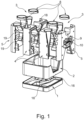
- the exploded view in Fig.1 shows the bottom part 1 with a condensate tray, the intermediate part 2 placed on the bottom part 1 in the final assembly state, and the two assemblies 3.
- the two assemblies 3 are made up of two individual components, namely an inner component 4 and an outer component 5.
- Air ducts 6 are molded into the assemblies 3, which each open into a duct opening 7 on the top of the assembly 3.
- the circular duct openings 7 are each lined with an annular nozzle 8.
- FIG.1 It is clearly visible that the left assembly 3, composed of the left outer component 5 and the inner component 4 arranged next to it, and the right assembly 3, composed of the outer component 5 on the outside right and the associated inner component 4, are axially symmetrical to one another.
- separating joint 15 between the base part 1 and the intermediate part 2 is also visible, as is its structure as a tongue and groove combination.
- the illustration of the Fig.1 the circumferential spring lip 16 protruding from the base part 1 in the area of the separating joint 15 is visible, which in the assembled state is in a Fig.1 not visible groove on the underside of the intermediate part 2.
- Fig.2 another hexagonal mounting hole 17 can be seen.
- the mounting opening 17 serves to accommodate a central heat exchanger, which is also hexagonal.
- centering bolts 18 and associated centering holes 19 can also be seen in the figures.
- the housing works as follows: In the embodiment, especially in Fig.2 A right-hand variant of the ventilation unit is shown. In the example in Fig.2 In the assembly 3 shown on the left, the mounting opening 17 and the receiving openings 10 for the heating registers and the receiving openings 9 for the filters are therefore closed. In the Fig.2 In the assembly 3 shown on the right, filters are mounted in the receiving openings 9 and heating registers in the receiving openings 10, and a heat exchanger is inserted into the mounting opening 17. Bypass motors 12 and fans are also present in the area of the fan arrangement 14.
- the inner components 4, the outer components 5 and the assemblies 3 are positively locked together in the area of their jointly formed vertical separating joints 15 and are additionally glued.
- the assemblies 3 are positively locked together with the intermediate part 2 and the intermediate part 2 in turn with the base part 1 in the area of the jointly formed horizontal separating joints 15 and are additionally glued.
- the ring connectors 8 are also inserted into the channel openings 7 of the air channels 6 and additionally glued. The ring connectors 8 prevent the separating joints 15 between the inner component 4 and the outer component 5 from breaking open in the area of the channel opening 7.
- Fig.3 corresponds essentially to Fig.1 , wherein in this embodiment, two symmetrical separating plates 30 are additionally provided between the intermediate part 2 and the assembled assemblies 3.
- the separating plates 30 are preferably made of metal, in particular aluminum or stainless steel.
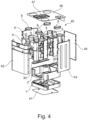
- Fig.4 shows schematically and exemplarily the ventilation unit of the Fig. 1 to 3 , around which a particularly metallic housing 40 is additionally arranged in an exploded view.
- the housing 40 comprises a base plate 41, several side walls 42, 43, 44 and 45 as well as a ceiling plate 46 with control panels 47 and 48.
- Fig.5 is also the Fig.4 shown ventilation device is shown schematically and by way of example, whereby only the housing 40 is shown in an exploded view and the rest of the ventilation device is shown in assembled form.
- Fig.6 The ventilation unit is shown schematically and exemplarily Fig.4 and 5 with the housing 40 also closed.
- Fig.7 and 8th show schematically and exemplarily the inner component 4 from two sides.
- Fig.7 the connection plane between two opposite inner components 4 is shown
- Fig.8 the view from the outside, i.e. the connection level with the external component 5.
- Fig.9 finally shows the outer component 5 schematically and exemplarily from the inside, that is, with a view to the connection between outer component 5 and inner component 4.
Landscapes
- Engineering & Computer Science (AREA)
- Chemical & Material Sciences (AREA)
- Combustion & Propulsion (AREA)
- Mechanical Engineering (AREA)
- General Engineering & Computer Science (AREA)
- Cooling Or The Like Of Electrical Apparatus (AREA)
Abstract
Description
- Die vorliegende Erfindung betrifft ein Lüftungsgerät mit einem Gehäuse und mit im Gehäuse angeordneten Luftkanälen und Gerätekomponenten. Die Luftkanäle dienen für einen durch das Lüftungsgerät hindurch geleiteten Abluftstrom und einen durch das Lüftungsgerät hindurch geleiteten Frischluftstrom beziehungsweise Außenluftstrom.
- Derartige Lüftungsgeräte sind aus dem Stand der Technik bekannt. Sie dienen beispielsweise zu Steuerung der Zuluft und Abluft in Gebäuden beziehungsweise in einzelnen Räumen von Gebäuden. Ferner werden Lüftungsgeräte für die Wärmerückgewinnung genutzt, indem die in der Abluft enthaltene Wärmeenergie der Abluft zumindest teilweise entzogen und auf die Frischluft übertragen wird.
- Die Gehäuse derartiger Lüftungsgeräte bestehen nach dem Stand der Technik aus expandiertem Polystyrol (EPS) und / oder expandiertem Polypropylen (EPP). Diese Kunststoffe haben den Vorteil, dass sie sehr gute Isolationseigenschaften aufweisen, sodass auf zusätzliche Isolationsmaterialen, welche beispielsweise in einem Blechgehäuse erforderlich sind, verzichtet werden kann. Die Kunststoffe bieten ferner vorteilhafte Gestaltungsmöglichkeiten, insbesondere in Bezug auf die Gestaltung der Luftkanäle. Allerdings sollten die Kunststoffteile möglichst keine Hinterschneidungen aufweisen, weil dies beim Entformen Probleme aufwerfen kann. Schließlich müssen die einzelnen Gerätebauteile miteinander verklebt werden, wobei die Klebeflächen oder Klebenähte stets die Gefahr von Leckagen mit sich bringen.
- Die Lüftungsgeräte sind zweckmäßig so gestaltet, dass die vorbeschriebenen, aus dem Gehäuse hausführenden Luftkanäle sowohl auf der linken Geräteseite als auch auf der rechten Geräteseite positioniert werden können. Dann kann dasselbe Gerät in Abhängigkeit von der Lage der Gebäudeanschlüsse sowohl in einer Linksals auch in einer Rechtsvariante betrieben werden.
- Der Erfindung liegt die Aufgabe zugrunde, ein Lüftungsgerät so zu gestalten, dass die einzelnen Gehäusebauteile einfach und betriebssicher zusammengefügt werden können und das Gerät sowohl in einer Links- als auch in einer Rechtsvariante betrieben werden kann.
- Diese Aufgabe löst das Lüftungsgerät mit den Merkmalen des Anspruchs 1.
- Erfindungsgemäß weist das Gehäuse expandiertes Polystyrol auf, welches nachfolgend kurz als "EPS" bezeichnet wird. Um das Gehäuse sowohl als Links- als auch als Rechtsvariante betreiben zu können, sind im Gehäuse wichtige Bestandteile wie der Zu- und Abluftkanal, der Bypasskanal oder der Heizregisterkanal sowie Leerräume für Filter oder Heizregister und Anschlüsse oder Positionsmöglichkeiten für Sensoren, Kabelleitungen, Kabelräume oder dergleichen in doppelter Ausführung vorgesehen. Realisiert ist dies durch einen im wesentlichen symmetrischen Aufbau des Gehäuses.
- Die Erfindung beruht dabei auf der einen Grundüberlegung, die erforderlichen Luftkanäle einerseits und Aufnahmeöffnungen, Anschlüsse oder Positionsmöglichkeiten für die Gerätekomponenten andererseits in zwei Baugruppen einzuformen. Die Verwendung von Baugruppen hat den Vorteil, dass in den Baugruppen die technische Funktionen des Lüftungsgerätes weitgehend zusammengefasst sind. In beide Baugruppen sind sowohl der Zu- und Abluftkanal, der Bypasskanal oder der Heizregisterkanal eingeformt. Weiterhin sind Aufnahmeöffnungen für Gerätekomponenten wie Sensoren, Heizregister, Bypassmotoren vorgesehen. Schließlich sind auch Kabelräume und Kabelkanäle in die Baugruppen eingeformt.
- Je nachdem, ob die Links- oder Rechtsvariante realisiert werden soll, wird eine der beiden Baugruppen durch den Einbau sämtlicher vorerwähnter Gerätekomponenten für den Betrieb als Lüftungsgerät ertüchtigt. Die andere Baugruppe wird entsprechend anderweitig genutzt, beispielsweise als Fortluftkanal ohne dort notwendige Heizeinrichtungen.
- Die Verwendung von EPS-Bauteilen ermöglicht es dabei, die Luftkanäle hinsichtlich ihrer Strömungseigenschaften zu optimieren. Die Luftkanäle sind strömungsgünstig so gestaltet, dass der Druckverlust im Luftstrom gering gehalten ist. Gerade die Bereiche der Luftkanäle, in denen hohe Luftgeschwindigkeiten herrschen, können optimal geformt werden. Die Luftkanäle können an den Lüfteraustrittskanal gut angepasst werden und insbesondere können Verwirbelungen durch plötzliche Querschnittsänderungen vermieden werden.
- Ferner ist es vorteilhaft in den EPS-Gehäusebauteilen dort Aussparungen an den Gehäusebauteilen vorzusehen, wo kein Material benötigt wird. Hierdurch wird sowohl Material als auch Prozesszeit bei der Fertigung der Teile eingespart.
- Das Lüftungsgerät folgt der weiteren Grundüberlegung, möglichst eine geringe Anzahl von Gerätebauteilen vorzusehen, wodurch die Anzahl der Trennfugen zwischen Gehäusebauteilen und damit auch die Anzahl von Klebeflächen oder Klebenähten reduziert ist.
- In vorteilhafter Ausgestaltung bestehen die beiden vorerwähnten Baugruppen nur aus jeweils zwei Einzelkomponenten. Auf diese Weise können die Gerätekomponenten und Kabelleitungen einfach in der jeweils zu ertüchtigen Baugruppe montiert werden. Vorteilhaft ist die Tatsache, dass mindestens eine oder beide Einzelkomponenten für die Baugruppen identisch ausgebildet sind. Auf diese Weise wird der Gedanke eines identischen Aufbaus auf der linken und auf der rechten Geräteseite durch die Verwendung dieser Gleichteile konsequent weiterverfolgt. Dies gilt auch für die zu montierenden Gerätekomponenten, die auch als Gleichteile ausgebildet sind, so dass sie in gleicher Weise in einer Linksanordnung oder einer Rechtsanordnung montiert werden können.
- In weiterer vorteilhafter Ausgestaltung ist vorgesehen, dass die Kanalöffnungen in den Baugruppen mit endseitigen Abschlussblenden, insbesondere mit als Ringstutzen ausgestalteten Abschlussblenden versehen werden. Auf diese Weise werden die Klebenähte im Bereich der Trennfuge zwischen den beiden Einzelkomponenten nicht auseinandergedrückt sondern entlastet, was die Dichtigkeit der Baugruppe steigert.
- Dem Grundgedanken der Verwendung weniger Gehäusebauteile folgend, ist das Gehäuse in weiterer vorteilhafter Ausgestaltung aus einem Bodenteil, einem Zwischenteil und den beiden Baugruppen mit den Ringstutzen zusammengesetzt. Auf diese Weise ist das Gehäuse aus lediglich zehn Gehäusebauteilen zusammengesetzt, wobei es sich bei den vier Ringstutzen und bei mindestens einer Einzelkomponente der beiden Baugruppen Gleichteile handelt, sodass maximal sechs unterschiedliche Gehäusebauteile zur Anwendung kommen. Sind beide Einzelkomponenten der Baugruppen jeweils identisch, reduziert sich die Teilevielfalt auf nur fünf unterschiedliche Gehäusebauteile.
- In weiterer Ausgestaltung der Erfindung sind die Gehäusebauteile so gestaltet, dass am Gehäuse jeweils nur überwiegend vertikale und / oder horizontale Trennfugen beziehungsweise Trennebenen zwischen den Gehäusebauteilen vorhanden sind. Mit dem Begriff "überwiegend" vertikal bzw. horizontal soll hier insbesondere eine solche Form bezeichnet werden, die eine vertikale bzw. horizontale Entfernungsrichtung der Gehäusebauteile ermöglicht. Anders ausgedrückt, der Verlauf der Trennfugen ist derart ausgeführt, dass eine Entformung in einer Richtung gewährleistet ist.
- Auf diese Weise können Hinterschnitte bzw. Schattenwurf an den Gehäusebauteilen konsequent vermieden werden. Die Verwendung von waagrecht und senkrecht aufeinander stehenden Trennebenen zwischen den Gehäusebauteilen vereinfacht auch das Entformen der einzelnen Gehäusebauteile bei der Fertigung, weil zwei Entformungsrichtungen zur Verfügung stehen. Hinzu kommt, dass durch die Aufteilung in mehrere Gehäuseteile konstruktiver Spielraum hinzugewonnen wird, während die Fertigung nicht weiter verkompliziert wird, da die Entformung in einer Richtung gewährleistet bleibt.
- In weiterer vorteilhafter Ausgestaltung sind die Trennfugen beziehungsweise Trennebenen zwischen den einzelnen Gehäusebauteilen als Nut-Feder-Verbindungen ausgestaltet. Diese Nut-Feder-Verbindungen bilden zunächst eine definierte Klebefuge zwischen den einzelnen Gehäusebauteilen. Die dadurch gebildeten Klebeflächen beziehungsweise Klebenähte sind besonders vorteilhaft, weil die Gefahr der Bildung von Leckagen infolge von Undichtigkeiten zwischen den einzelnen Gehäusebauteilen deutlich reduziert ist. Die Nut-Feder-Verbindungen im Bereich der Trennfugen beziehungsweise Trennebenen der einzelnen Gehäusebauteile erleichtern zudem die Montage des Gehäuses.
- In weiterer vorteilhafter Ausgestaltung können im Bereich der Trennfugen beziehungsweise Trennebenen zwischen einander benachbarten Gehäusebauteilen Zentrierbolzen in einem Bauteil und zu den Zentrierbolzen komplementäre Zentrierbohrungen im zugeordneten anderen Bauteil vorgesehen sein. Auf diese Weise ist eine passungsgerechte Zuordnung und Montage der einzelnen Gehäusebauteile sehr einfach und gut möglich.
- Anhand des in den Zeichnungsfiguren gezeigten Lüftungsgeräts ist die Erfindung weiter erläutert. Es zeigen:
- Fig. 1
- eine Explosionsdarstellung des Gehäuses des Lüftungsgeräts
- Fig. 2
- eine Draufsicht auf die Innenseiten der beiden Baugruppen des Lüftungsgerätes,
- Fig. 3
- eine weitere Explosionsdarstellung einer anderen Ausführungsform des Lüftungsgeräts,
- Fig. 4 bis 6
- eine Ausführung des Lüftungsgeräts mit Gehäuse in teilweiser Explosionsdarstellung,
- Fig. 7 bis 9
- Detailansichten auf Verbindungsebenen der Innenkomponente bzw. der Außenkomponente.
- Identische und baugleiche Teile sind mit identischen Bezugsziffern versehen. Einzelne Figuren zeigen der besseren Übersichtlichkeit halber nicht sämtliche Bezugszeichen. Die Figuren enthalten teilweise vereinfachte oder schematische Darstellungen. Verschiedene Ansichten gleicher Teile können unterschiedlich skaliert sein.
- Die Explosionsdarstellung in
Fig. 1 zeigt zunächst unten das Bodenteil 1 mit einer Kondensatwanne, das auf das Bodenteil 1 im Montageendzustand aufgestellte Zwischenteil 2 sowie die beiden Baugruppen 3. Die beiden Baugruppen 3 setzen sich aus zwei Einzelkomponenten, nämlich jeweils einer Innenkomponente 4 und einer Außenkomponente 5 zusammen. In die Baugruppen 3 sind Luftkanäle 6 eingeformt, die an der Oberseite der Baugruppe 3 jeweils in eine Kanalöffnung 7 münden. Die kreisrunden Kanalöffnungen 7 sind dabei mit jeweils einem Ringstutzen 8 ausgekleidet. Das Bodenteil 1, das Zwischenteil 2 die aus den Innenkomponenten 4 und Außenkomponenten 5 zusammengesetzten Baugruppen 3 sowie die Ringstutzen 8 sind Formteile aus expandiertem Polystyrol [= EPS]. - In die beiden Außenkomponenten 5 sind jeweils Aufnahmeöffnungen 9 für Filter und darunter Aufnahmeöffnungen 10 für Heizregister eingeformt. In
Fig. 1 gut erkennbar ist die Tatsache, dass die aus der linken Außenkomponente 5 und der daneben angeordneten Innenkomponente 4 zusammengesetzte linke Baugruppe 3 und die aus der Außenkomponente 5 außen rechts und der zugehörigen Innenkomponente 4 zusammengesetzte rechte Baugruppe 3 zueinander achsensymmetrisch aufgebaut sind. - Dieser achsensymmetrische Aufbau der Baugruppen 3 ist auch in
Fig. 2 wiedergegeben. In den Baugruppen 3 erkennbar sind zunächst die Kanalöffnungen 7 der Luftkanäle 6, die Aufnahmeöffnungen 9 für Filter sowie die Aufnahmeöffnungen 10 für Heizregister. Ferner sind Bypässe 11 mit ihren einsetzbaren Bypassmotoren 12 vorgesehen sowie Leerräume 13 für Kabel oder Sensoren sowie eine Lüfteranordnung 14 im Bodenteil 1. - In der Darstellung der
Fig. 2 ist auch die Trennfuge 15 zwischen dem Bodenteil 1 und dem Zwischenteil 2 erkennbar sowie ihr Aufbau als Nut-Feder-Kombination. Auch in der Darstellung derFig. 1 ist die aus dem Bodenteil 1 im Bereich der Trennfuge 15 vorspringende umlaufende Federlippe 16 erkennbar, welche im montierten Zustand in eine inFig. 1 nicht erkennbare Nut an der Unterseite des Zwischenteils 2 eingreift. Ferner ist inFig. 2 noch eine hexagonale Montageöffnung 17 erkennbar. Die Montageöffnung 17 dient zur Aufnahme eines ebenso hexagonalen zentralen Wärmeübertragers. Schließlich sind in den Figuren auch Zentrierbolzen 18 und zugehörige Zentrierbohrungen 19 erkennbar. - Die Funktionsweise des Gehäuses ist folgende:
Im Ausführungsbeispiel, insbesondere inFig. 2 ist eine Rechtsvariante des Lüftungsgerätes gezeigt. Bei der im Ausführungsbeispiel inFig. 2 links dargestellten Baugruppe 3 sind deshalb die Montageöffnung 17 sowie die Aufnahmeöffnungen 10 für die Heizregister sowie die Aufnahmeöffnungen 9 für die Filter verschlossen. In der inFig. 2 rechts abgebildeten Baugruppe 3 werden in den Aufnahmeöffnungen 9 Filter und in den Aufnahmeöffnungen 10 Heizregister montiert, sowie in die Montageöffnung 17 ein Wärmeübertrager eingebracht. Auch sind sowohl Bypassmotoren 12 als auch Lüfter im Bereich der Lüfteranordnung 14 vorhanden. - Die Innenkomponenten 4, die Aussenkompontenen 5 und die Baugruppen 3 sind im Bereich ihrer gemeinsam ausgebildeten vertikalen Trennfugen 15 miteinander formschlüssig verrastet und zusätzlich verklebt. Die Baugruppen 3 sind mit dem Zwischenteil 2 und das Zwischenteil 2 wiederum mit dem Bodenteil 1 im Bereich der gemeinsam ausgebildeten horizontalen Trennfugen 15 miteinander formschlüssig verrastet und zusätzlich verklebt. Auch sind in die Kanalöffnungen 7 der Luftkanäle 6 die Ringstutzen 8 eingesetzt und zusätzlich verklebt. Die Ringstutzen 8 verhindern ein Aufbrechen der Trennfugen 15 zwischen der Innenkomponente 4 und der Außenkomponente 5 im Bereich der Kanalöffnung 7.
-
Fig. 3 entspricht im WesentlichenFig. 1 , wobei zusätzlich zwischen dem Zwischenteil 2 und den zusammengesetzten Baugruppen 3 in dieser Ausführung zwei ebenfalls symmetrisch ausgebildete Trennbleche 30 ausgeführt sind. Die Trennbleiche 30 bestehen vorzugsweise aus Metall, insbesondere Aluminium oder Edelstahl. -
Fig. 4 zeigt schematisch und exemplarisch das Lüftungsgerät derFig. 1 bis 3 , um das zusätzlich ein insbesondere metallisches Gehäuse 40 angeordnet ist in Explosionsdarstellung. Das Gehäuse 40 umfasst eine Bodenplatte 41, mehrere Seitenwände 42, 43, 44 und 45 sowie eine Deckenpatte 46 mit Bedienfeld 47 und 48. - In
Fig. 5 ist ebenfalls das inFig. 4 gezeigte Lüftungsgerät schematisch und exemplarisch gezeigt, wobei hier lediglich das Gehäuse 40 in Explosionsdarstellung gezeigt ist und der Rest des Lüftungsgeräts in zusammengesetzter Form abgebildet ist. - In
Fig. 6 ist das Lüftungsgerät schematisch und exemplarisch ausFig. 4 und5 mit ebenfalls geschlossenem Gehäuse 40 gezeigt. -
Fig. 7 und8 zeigen schematisch und exemplarisch die Innenkomponente 4 von zwei Seiten. InFig. 7 ist die Verbindungsebene zwischen zwei gegenüberliegenden Innenkomponenten 4 gezeigt, währendFig. 8 die Sicht von außen, also auf die Verbindungsebene mit der Außenkomponete 5 zeigt. -
Fig. 9 zeigt schließlich die Außenkomponente 5 schematisch und exemplarisch von Innen, das heißt mit Blick auf die Verbindung zwischen Außenkomponente 5 und Innenkomponente 4. -
- 1. Bodenteil
- 2. Zwischenteil
- 3. Baugruppe
- 4. Innenkomponente
- 5. Außenkomponente
- 6. Luftkanal
- 7. Kanalöffnung
- 8. Ringstutzen
- 9. Aufnahmeöffnung (Filter)
- 10. Aufnahmeöffnung (Heizregister)
- 11. Bypass
- 12. Bypassmotor
- 13. Leerraum
- 14. Lüfteranordnung
- 15. Trennfuge
- 16. Federlippe
- 17. Montageöffnung
- 18. Zentrierbolzen
- 19. Zentrierbohrung
Claims (10)
- Lüftungsgerät mit einem Gehäuse und mit im Gehäuse angeordneten Luftkanälen (6) und Gerätekomponenten,
dadurch gekennzeichnet,
dass das Gehäuse expandiertes Polystyrol [= EPS] aufweist, dass das Gehäuse mindestens zwei Baugruppen (3) mit eingeformten Luftkanälen (6) und mit Aufnahmeöffnungen (9, 10) für die Gerätekomponenten aufweist und dass die Baugruppen (3) bezogen auf die Mittellängsachse des Gehäuses symmetrisch zueinander aufgebaut sind. - Lüftungsgerät nach Anspruch 1
dadurch gekennzeichnet,
dass die Baugruppen (3) aus jeweils zwei Einzelkomponenten (4,5) zusammengesetzt sind und dass mindestens eine Einzelkomponente (4,5) an beiden Baugruppen (3) identisch ausgebildet ist. - Lüftungsgerät nach Anspruch 1 oder 2
dadurch gekennzeichnet,
dass die Baugruppen (3) jeweils zwei Kanalöffnungen (7) mit endseitigen Abschlussblenden aufweisen. - Lüftungsgerät nach Anspruch 3,
gekennzeichnet durch,
kreisförmige Kanalöffnungen (7) mit identischem Durchmesser und mit identischen, als Ringstutzen (8) ausgestalteten Abschlussblenden. - Lüftungsgerät nach einem der Ansprüche 1 bis 4,
dadurch gekennzeichnet,
dass das Gehäuse aus einem Bodenteil (1) mit einer Kondensatwanne, einem Zwischenteil (2) zur zumindest teilweisen Aufnahme einer zentralen Gerätekomponente, beispielsweise eines Wärmeübertragers und aus den beiden Baugruppen (3) zusammengesetzt ist. - Lüftungsgerät nach einem der Ansprüche 1 bis 5
dadurch gekennzeichnet,
dass die Trennfugen (15) zwischen den Gehäusebauteilen im Wesentlichen vertikal oder horizontal verlaufende Trennebenen definieren, derart, dass eine Entformung in einer Richtung ermöglicht ist. - Lüftungsgerät nach einem der Ansprüche 1 bis 6
dadurch gekennzeichnet,
dass die Trennfugen (15) zwischen den Gehäusebauteilen als Nut-Feder-Verbindungen ausgestaltet sind. - Lüftungsgerät nach einem der Ansprüche 1 bis 7,
dadurch gekennzeichnet,
dass einander benachbarte Gehäusebauteile im Bereich ihrer Trennfugen (15) Zentrierbolzen (18) und zu den Zentrierbolzen (18) komplementäre Zentrierbohrungen (19) aufweisen. - Lüftungsgerät nach Anspruch 5, wobei wenigstens ein Trennblech (30), insbesondere ein metallisches Trennblech, zwischen dem Zwischenteil (2) und den beiden Baugruppen (3) ausgebildet ist.
- Lüftungsgerät nach einem der vorstehenden Ansprüche, wobei das Lüftungsgerät von einem insbesondere metallischen Gehäuse (40) eingefasst ist.
Applications Claiming Priority (1)
| Application Number | Priority Date | Filing Date | Title |
|---|---|---|---|
| DE102022134305.7A DE102022134305A1 (de) | 2022-12-21 | 2022-12-21 | Lüftungsgerät |
Publications (2)
| Publication Number | Publication Date |
|---|---|
| EP4390263A1 true EP4390263A1 (de) | 2024-06-26 |
| EP4390263B1 EP4390263B1 (de) | 2025-09-24 |
Family
ID=88206898
Family Applications (1)
| Application Number | Title | Priority Date | Filing Date |
|---|---|---|---|
| EP23200182.6A Active EP4390263B1 (de) | 2022-12-21 | 2023-09-27 | Lüftungsgerät |
Country Status (3)
| Country | Link |
|---|---|
| EP (1) | EP4390263B1 (de) |
| DE (1) | DE102022134305A1 (de) |
| PL (1) | PL4390263T3 (de) |
Citations (5)
| Publication number | Priority date | Publication date | Assignee | Title |
|---|---|---|---|---|
| DE102008006021A1 (de) * | 2007-02-19 | 2008-08-28 | Maico Elektroapparate-Fabrik Gmbh | Luftverteiler, Luftverteiler-System sowie Luftverteilungs-System |
| WO2008105586A1 (en) * | 2007-02-27 | 2008-09-04 | Moregensengineering Co., Ltd. | Ventilation system for energy recovery |
| GB2491516A (en) * | 2008-01-15 | 2012-12-05 | Titon Hardware | Electric motor drive circuit having a calibration setting and a run setting |
| GB2497568A (en) * | 2011-12-14 | 2013-06-19 | Polypipe Ltd | Ventilation module suitable for use in a mechanical ventilation and heat recovery unit |
| EP3450863A1 (de) * | 2017-09-01 | 2019-03-06 | Enervent Zehnder Oy | Luftzufuhrvorrichtung |
Family Cites Families (1)
| Publication number | Priority date | Publication date | Assignee | Title |
|---|---|---|---|---|
| ITTO20130008A1 (it) * | 2013-01-09 | 2014-07-10 | Thesan S P A | Dispositivo di scambio d'aria per edifici |
-
2022
- 2022-12-21 DE DE102022134305.7A patent/DE102022134305A1/de active Pending
-
2023
- 2023-09-27 EP EP23200182.6A patent/EP4390263B1/de active Active
- 2023-09-27 PL PL23200182.6T patent/PL4390263T3/pl unknown
Patent Citations (5)
| Publication number | Priority date | Publication date | Assignee | Title |
|---|---|---|---|---|
| DE102008006021A1 (de) * | 2007-02-19 | 2008-08-28 | Maico Elektroapparate-Fabrik Gmbh | Luftverteiler, Luftverteiler-System sowie Luftverteilungs-System |
| WO2008105586A1 (en) * | 2007-02-27 | 2008-09-04 | Moregensengineering Co., Ltd. | Ventilation system for energy recovery |
| GB2491516A (en) * | 2008-01-15 | 2012-12-05 | Titon Hardware | Electric motor drive circuit having a calibration setting and a run setting |
| GB2497568A (en) * | 2011-12-14 | 2013-06-19 | Polypipe Ltd | Ventilation module suitable for use in a mechanical ventilation and heat recovery unit |
| EP3450863A1 (de) * | 2017-09-01 | 2019-03-06 | Enervent Zehnder Oy | Luftzufuhrvorrichtung |
Also Published As
| Publication number | Publication date |
|---|---|
| DE102022134305A1 (de) | 2024-06-27 |
| PL4390263T3 (pl) | 2026-02-16 |
| EP4390263B1 (de) | 2025-09-24 |
Similar Documents
| Publication | Publication Date | Title |
|---|---|---|
| EP1306638B1 (de) | Gehäuseloser Plattenwärmetauscher | |
| DE102011051489B4 (de) | Gebläse-Luftansaugungsvorrichtung | |
| DE69004220T2 (de) | Wärmetauscher mit einer umfangsförmigen Zirkulation. | |
| DD139643A5 (de) | Einrichtung bei einem verdunstungskuehler | |
| EP2965017B1 (de) | Luftverteileinrichtung | |
| EP2118577A1 (de) | Luftauslass und verfahren zu dessen herstellung | |
| DE202011000453U1 (de) | Drosseleinrichtung für den Luftdurchsatz durch einen Lufteinlass | |
| EP2745664B1 (de) | Bodenwanne zum verbinden eines dachaufbau-kühlgerätes mit dem dach eines schaltschrankes | |
| EP3599169B1 (de) | Mischerbaugruppe mit umgebendem filterelement, stauraum mit mischerbaugruppe, fahrzeug mit einem stauraum und verfahren zum einbau einer mischerbaugruppe | |
| DE19737531C2 (de) | Wärmetauscherbausatz und Klimatisierungsmeßgerät | |
| EP4390263B1 (de) | Lüftungsgerät | |
| EP1095836B2 (de) | Unterflurcontainer für Schienenfahrzeuge | |
| EP1725823A1 (de) | Vorrichtung zum austausch von wärme und verfahren zur herstellung einer solchen vorrichtung | |
| EP3034337B1 (de) | Luftführungssystem für ein kraftfahrzeug | |
| EP3724555B1 (de) | Lüftungsgerät und verfahren zu dessen montage und demontage | |
| DE102007032154A1 (de) | Lüftungseinrichtung | |
| WO1999067008A1 (de) | Filtersystem mit v-förmiger filterpatrone | |
| EP3995748B1 (de) | Raumlüftungssystem | |
| DE3842814A1 (de) | Luftverteilsystem | |
| EP1674368B1 (de) | Klimagerät für Schienenfahrzeuge | |
| EP2665350A2 (de) | Gebläseeinheit zur Kühlung von Aggregaten, wie elektrische/elektronische Baugruppen, Geräte und dergleichen | |
| DE10215604A1 (de) | Luftansaugkanalsystem für Brennkraftmaschinen | |
| DE202024106520U1 (de) | Klimatisierungsgerät zum deckennahen Einbau | |
| DE1600662C (de) | Anschlußstuck mit kastenförmigen Teilen fur konzentrische Doppelrohr leitungen | |
| DE202015102781U1 (de) | Lüftungseinrichtung für Reinräume |
Legal Events
| Date | Code | Title | Description |
|---|---|---|---|
| PUAI | Public reference made under article 153(3) epc to a published international application that has entered the european phase |
Free format text: ORIGINAL CODE: 0009012 |
|
| STAA | Information on the status of an ep patent application or granted ep patent |
Free format text: STATUS: THE APPLICATION HAS BEEN PUBLISHED |
|
| AK | Designated contracting states |
Kind code of ref document: A1 Designated state(s): AL AT BE BG CH CY CZ DE DK EE ES FI FR GB GR HR HU IE IS IT LI LT LU LV MC ME MK MT NL NO PL PT RO RS SE SI SK SM TR |
|
| STAA | Information on the status of an ep patent application or granted ep patent |
Free format text: STATUS: REQUEST FOR EXAMINATION WAS MADE |
|
| 17P | Request for examination filed |
Effective date: 20250102 |
|
| GRAP | Despatch of communication of intention to grant a patent |
Free format text: ORIGINAL CODE: EPIDOSNIGR1 |
|
| STAA | Information on the status of an ep patent application or granted ep patent |
Free format text: STATUS: GRANT OF PATENT IS INTENDED |
|
| INTG | Intention to grant announced |
Effective date: 20250429 |
|
| GRAS | Grant fee paid |
Free format text: ORIGINAL CODE: EPIDOSNIGR3 |
|
| GRAA | (expected) grant |
Free format text: ORIGINAL CODE: 0009210 |
|
| STAA | Information on the status of an ep patent application or granted ep patent |
Free format text: STATUS: THE PATENT HAS BEEN GRANTED |
|
| AK | Designated contracting states |
Kind code of ref document: B1 Designated state(s): AL AT BE BG CH CY CZ DE DK EE ES FI FR GB GR HR HU IE IS IT LI LT LU LV MC ME MK MT NL NO PL PT RO RS SE SI SK SM TR |
|
| REG | Reference to a national code |
Ref country code: GB Ref legal event code: FG4D Free format text: NOT ENGLISH |
|
| REG | Reference to a national code |
Ref country code: CH Ref legal event code: EP |
|
| REG | Reference to a national code |
Ref country code: DE Ref legal event code: R096 Ref document number: 502023001851 Country of ref document: DE |
|
| PGFP | Annual fee paid to national office [announced via postgrant information from national office to epo] |
Ref country code: AT Payment date: 20251020 Year of fee payment: 3 |
|
| REG | Reference to a national code |
Ref country code: IE Ref legal event code: FG4D Free format text: LANGUAGE OF EP DOCUMENT: GERMAN |
|
| REG | Reference to a national code |
Ref country code: NL Ref legal event code: FP |
|
| PGFP | Annual fee paid to national office [announced via postgrant information from national office to epo] |
Ref country code: DE Payment date: 20251021 Year of fee payment: 3 |
|
| PG25 | Lapsed in a contracting state [announced via postgrant information from national office to epo] |
Ref country code: NO Free format text: LAPSE BECAUSE OF FAILURE TO SUBMIT A TRANSLATION OF THE DESCRIPTION OR TO PAY THE FEE WITHIN THE PRESCRIBED TIME-LIMIT Effective date: 20251224 |
|
| REG | Reference to a national code |
Ref country code: LT Ref legal event code: MG9D |
|
| PG25 | Lapsed in a contracting state [announced via postgrant information from national office to epo] |
Ref country code: FI Free format text: LAPSE BECAUSE OF FAILURE TO SUBMIT A TRANSLATION OF THE DESCRIPTION OR TO PAY THE FEE WITHIN THE PRESCRIBED TIME-LIMIT Effective date: 20250924 |
|
| PG25 | Lapsed in a contracting state [announced via postgrant information from national office to epo] |
Ref country code: HR Free format text: LAPSE BECAUSE OF FAILURE TO SUBMIT A TRANSLATION OF THE DESCRIPTION OR TO PAY THE FEE WITHIN THE PRESCRIBED TIME-LIMIT Effective date: 20250924 |
|
| PGFP | Annual fee paid to national office [announced via postgrant information from national office to epo] |
Ref country code: FR Payment date: 20251126 Year of fee payment: 4 |
|
| PG25 | Lapsed in a contracting state [announced via postgrant information from national office to epo] |
Ref country code: GR Free format text: LAPSE BECAUSE OF FAILURE TO SUBMIT A TRANSLATION OF THE DESCRIPTION OR TO PAY THE FEE WITHIN THE PRESCRIBED TIME-LIMIT Effective date: 20251225 |
|
| PG25 | Lapsed in a contracting state [announced via postgrant information from national office to epo] |
Ref country code: SE Free format text: LAPSE BECAUSE OF FAILURE TO SUBMIT A TRANSLATION OF THE DESCRIPTION OR TO PAY THE FEE WITHIN THE PRESCRIBED TIME-LIMIT Effective date: 20250924 |
|
| PGFP | Annual fee paid to national office [announced via postgrant information from national office to epo] |
Ref country code: CZ Payment date: 20251113 Year of fee payment: 3 |
|
| PG25 | Lapsed in a contracting state [announced via postgrant information from national office to epo] |
Ref country code: LV Free format text: LAPSE BECAUSE OF FAILURE TO SUBMIT A TRANSLATION OF THE DESCRIPTION OR TO PAY THE FEE WITHIN THE PRESCRIBED TIME-LIMIT Effective date: 20250924 |
|
| PG25 | Lapsed in a contracting state [announced via postgrant information from national office to epo] |
Ref country code: BG Free format text: LAPSE BECAUSE OF FAILURE TO SUBMIT A TRANSLATION OF THE DESCRIPTION OR TO PAY THE FEE WITHIN THE PRESCRIBED TIME-LIMIT Effective date: 20250924 |
|
| PG25 | Lapsed in a contracting state [announced via postgrant information from national office to epo] |
Ref country code: RS Free format text: LAPSE BECAUSE OF FAILURE TO SUBMIT A TRANSLATION OF THE DESCRIPTION OR TO PAY THE FEE WITHIN THE PRESCRIBED TIME-LIMIT Effective date: 20251224 |
|
| PG25 | Lapsed in a contracting state [announced via postgrant information from national office to epo] |
Ref country code: SM Free format text: LAPSE BECAUSE OF FAILURE TO SUBMIT A TRANSLATION OF THE DESCRIPTION OR TO PAY THE FEE WITHIN THE PRESCRIBED TIME-LIMIT Effective date: 20250924 |
|
| PG25 | Lapsed in a contracting state [announced via postgrant information from national office to epo] |
Ref country code: ES Free format text: LAPSE BECAUSE OF FAILURE TO SUBMIT A TRANSLATION OF THE DESCRIPTION OR TO PAY THE FEE WITHIN THE PRESCRIBED TIME-LIMIT Effective date: 20250924 |
|
| PG25 | Lapsed in a contracting state [announced via postgrant information from national office to epo] |
Ref country code: IT Free format text: LAPSE BECAUSE OF FAILURE TO SUBMIT A TRANSLATION OF THE DESCRIPTION OR TO PAY THE FEE WITHIN THE PRESCRIBED TIME-LIMIT Effective date: 20250924 Ref country code: RO Free format text: LAPSE BECAUSE OF FAILURE TO SUBMIT A TRANSLATION OF THE DESCRIPTION OR TO PAY THE FEE WITHIN THE PRESCRIBED TIME-LIMIT Effective date: 20250924 |
|
| PG25 | Lapsed in a contracting state [announced via postgrant information from national office to epo] |
Ref country code: IS Free format text: LAPSE BECAUSE OF FAILURE TO SUBMIT A TRANSLATION OF THE DESCRIPTION OR TO PAY THE FEE WITHIN THE PRESCRIBED TIME-LIMIT Effective date: 20260124 |
|
| PG25 | Lapsed in a contracting state [announced via postgrant information from national office to epo] |
Ref country code: PT Free format text: LAPSE BECAUSE OF FAILURE TO SUBMIT A TRANSLATION OF THE DESCRIPTION OR TO PAY THE FEE WITHIN THE PRESCRIBED TIME-LIMIT Effective date: 20260126 |
|
| PGFP | Annual fee paid to national office [announced via postgrant information from national office to epo] |
Ref country code: PL Payment date: 20251114 Year of fee payment: 3 |
|
| PG25 | Lapsed in a contracting state [announced via postgrant information from national office to epo] |
Ref country code: EE Free format text: LAPSE BECAUSE OF FAILURE TO SUBMIT A TRANSLATION OF THE DESCRIPTION OR TO PAY THE FEE WITHIN THE PRESCRIBED TIME-LIMIT Effective date: 20250924 Ref country code: SK Free format text: LAPSE BECAUSE OF FAILURE TO SUBMIT A TRANSLATION OF THE DESCRIPTION OR TO PAY THE FEE WITHIN THE PRESCRIBED TIME-LIMIT Effective date: 20250924 |
|
| PG25 | Lapsed in a contracting state [announced via postgrant information from national office to epo] |
Ref country code: LU Free format text: LAPSE BECAUSE OF NON-PAYMENT OF DUE FEES Effective date: 20250927 |
|
| REG | Reference to a national code |
Ref country code: BE Ref legal event code: MM Effective date: 20250930 |
|
| REG | Reference to a national code |
Ref country code: DE Ref legal event code: R097 Ref document number: 502023001851 Country of ref document: DE |
|
| PG25 | Lapsed in a contracting state [announced via postgrant information from national office to epo] |
Ref country code: MC Free format text: LAPSE BECAUSE OF FAILURE TO SUBMIT A TRANSLATION OF THE DESCRIPTION OR TO PAY THE FEE WITHIN THE PRESCRIBED TIME-LIMIT Effective date: 20250924 Ref country code: LT Free format text: LAPSE BECAUSE OF FAILURE TO SUBMIT A TRANSLATION OF THE DESCRIPTION OR TO PAY THE FEE WITHIN THE PRESCRIBED TIME-LIMIT Effective date: 20250924 |
|
| PG25 | Lapsed in a contracting state [announced via postgrant information from national office to epo] |
Ref country code: DK Free format text: LAPSE BECAUSE OF FAILURE TO SUBMIT A TRANSLATION OF THE DESCRIPTION OR TO PAY THE FEE WITHIN THE PRESCRIBED TIME-LIMIT Effective date: 20250924 |
|
| PG25 | Lapsed in a contracting state [announced via postgrant information from national office to epo] |
Ref country code: BE Free format text: LAPSE BECAUSE OF NON-PAYMENT OF DUE FEES Effective date: 20250930 Ref country code: IE Free format text: LAPSE BECAUSE OF NON-PAYMENT OF DUE FEES Effective date: 20250927 |
|
| PLBE | No opposition filed within time limit |
Free format text: ORIGINAL CODE: 0009261 |
|
| STAA | Information on the status of an ep patent application or granted ep patent |
Free format text: STATUS: NO OPPOSITION FILED WITHIN TIME LIMIT |
|
| REG | Reference to a national code |
Ref country code: CH Ref legal event code: L10 Free format text: ST27 STATUS EVENT CODE: U-0-0-L10-L00 (AS PROVIDED BY THE NATIONAL OFFICE) Effective date: 20260805 |