EP4389634B1 - Abtrennbare verschlusskappe für einen behälter mit hals - Google Patents
Abtrennbare verschlusskappe für einen behälter mit hals Download PDFInfo
- Publication number
- EP4389634B1 EP4389634B1 EP23213079.9A EP23213079A EP4389634B1 EP 4389634 B1 EP4389634 B1 EP 4389634B1 EP 23213079 A EP23213079 A EP 23213079A EP 4389634 B1 EP4389634 B1 EP 4389634B1
- Authority
- EP
- European Patent Office
- Prior art keywords
- cage
- locking cap
- outer body
- capsule
- cap
- Prior art date
- Legal status (The legal status is an assumption and is not a legal conclusion. Google has not performed a legal analysis and makes no representation as to the accuracy of the status listed.)
- Active
Links
Images



Classifications
-
- B—PERFORMING OPERATIONS; TRANSPORTING
- B65—CONVEYING; PACKING; STORING; HANDLING THIN OR FILAMENTARY MATERIAL
- B65D—CONTAINERS FOR STORAGE OR TRANSPORT OF ARTICLES OR MATERIALS, e.g. BAGS, BARRELS, BOTTLES, BOXES, CANS, CARTONS, CRATES, DRUMS, JARS, TANKS, HOPPERS, FORWARDING CONTAINERS; ACCESSORIES, CLOSURES, OR FITTINGS THEREFOR; PACKAGING ELEMENTS; PACKAGES
- B65D41/00—Caps, e.g. crown caps or crown seals, i.e. members having parts arranged for engagement with the external periphery of a neck or wall defining a pouring opening or discharge aperture; Protective cap-like covers for closure members, e.g. decorative covers of metal foil or paper
- B65D41/02—Caps or cap-like covers without lines of weakness, tearing strips, tags, or like opening or removal devices
- B65D41/28—Caps combined with stoppers
-
- B—PERFORMING OPERATIONS; TRANSPORTING
- B65—CONVEYING; PACKING; STORING; HANDLING THIN OR FILAMENTARY MATERIAL
- B65D—CONTAINERS FOR STORAGE OR TRANSPORT OF ARTICLES OR MATERIALS, e.g. BAGS, BARRELS, BOTTLES, BOXES, CANS, CARTONS, CRATES, DRUMS, JARS, TANKS, HOPPERS, FORWARDING CONTAINERS; ACCESSORIES, CLOSURES, OR FITTINGS THEREFOR; PACKAGING ELEMENTS; PACKAGES
- B65D45/00—Clamping or other pressure-applying devices for securing or retaining closure members
- B65D45/02—Clamping or other pressure-applying devices for securing or retaining closure members for applying axial pressure to engage closure with sealing surface
- B65D45/30—Annular members, e.g. with snap-over action or screw-threaded
-
- B—PERFORMING OPERATIONS; TRANSPORTING
- B65—CONVEYING; PACKING; STORING; HANDLING THIN OR FILAMENTARY MATERIAL
- B65D—CONTAINERS FOR STORAGE OR TRANSPORT OF ARTICLES OR MATERIALS, e.g. BAGS, BARRELS, BOTTLES, BOXES, CANS, CARTONS, CRATES, DRUMS, JARS, TANKS, HOPPERS, FORWARDING CONTAINERS; ACCESSORIES, CLOSURES, OR FITTINGS THEREFOR; PACKAGING ELEMENTS; PACKAGES
- B65D41/00—Caps, e.g. crown caps or crown seals, i.e. members having parts arranged for engagement with the external periphery of a neck or wall defining a pouring opening or discharge aperture; Protective cap-like covers for closure members, e.g. decorative covers of metal foil or paper
- B65D41/32—Caps or cap-like covers with lines of weakness, tearing-strips, tags, or like opening or removal devices, e.g. to facilitate formation of pouring openings
- B65D41/58—Caps or cap-like covers combined with stoppers
-
- A—HUMAN NECESSITIES
- A61—MEDICAL OR VETERINARY SCIENCE; HYGIENE
- A61J—CONTAINERS SPECIALLY ADAPTED FOR MEDICAL OR PHARMACEUTICAL PURPOSES; DEVICES OR METHODS SPECIALLY ADAPTED FOR BRINGING PHARMACEUTICAL PRODUCTS INTO PARTICULAR PHYSICAL OR ADMINISTERING FORMS; DEVICES FOR ADMINISTERING FOOD OR MEDICINES ORALLY; BABY COMFORTERS; DEVICES FOR RECEIVING SPITTLE
- A61J1/00—Containers specially adapted for medical or pharmaceutical purposes
- A61J1/14—Details; Accessories therefor
- A61J1/1412—Containers with closing means, e.g. caps
-
- B—PERFORMING OPERATIONS; TRANSPORTING
- B65—CONVEYING; PACKING; STORING; HANDLING THIN OR FILAMENTARY MATERIAL
- B65D—CONTAINERS FOR STORAGE OR TRANSPORT OF ARTICLES OR MATERIALS, e.g. BAGS, BARRELS, BOTTLES, BOXES, CANS, CARTONS, CRATES, DRUMS, JARS, TANKS, HOPPERS, FORWARDING CONTAINERS; ACCESSORIES, CLOSURES, OR FITTINGS THEREFOR; PACKAGING ELEMENTS; PACKAGES
- B65D41/00—Caps, e.g. crown caps or crown seals, i.e. members having parts arranged for engagement with the external periphery of a neck or wall defining a pouring opening or discharge aperture; Protective cap-like covers for closure members, e.g. decorative covers of metal foil or paper
- B65D41/32—Caps or cap-like covers with lines of weakness, tearing-strips, tags, or like opening or removal devices, e.g. to facilitate formation of pouring openings
- B65D41/34—Threaded or like caps or cap-like covers provided with tamper elements formed in, or attached to, the closure skirt
- B65D41/3423—Threaded or like caps or cap-like covers provided with tamper elements formed in, or attached to, the closure skirt with flexible tabs, or elements rotated from a non-engaging to an engaging position, formed on the tamper element or in the closure skirt
-
- B—PERFORMING OPERATIONS; TRANSPORTING
- B65—CONVEYING; PACKING; STORING; HANDLING THIN OR FILAMENTARY MATERIAL
- B65D—CONTAINERS FOR STORAGE OR TRANSPORT OF ARTICLES OR MATERIALS, e.g. BAGS, BARRELS, BOTTLES, BOXES, CANS, CARTONS, CRATES, DRUMS, JARS, TANKS, HOPPERS, FORWARDING CONTAINERS; ACCESSORIES, CLOSURES, OR FITTINGS THEREFOR; PACKAGING ELEMENTS; PACKAGES
- B65D51/00—Closures not otherwise provided for
- B65D51/002—Closures to be pierced by an extracting-device for the contents and fixed on the container by separate retaining means
-
- B—PERFORMING OPERATIONS; TRANSPORTING
- B65—CONVEYING; PACKING; STORING; HANDLING THIN OR FILAMENTARY MATERIAL
- B65D—CONTAINERS FOR STORAGE OR TRANSPORT OF ARTICLES OR MATERIALS, e.g. BAGS, BARRELS, BOTTLES, BOXES, CANS, CARTONS, CRATES, DRUMS, JARS, TANKS, HOPPERS, FORWARDING CONTAINERS; ACCESSORIES, CLOSURES, OR FITTINGS THEREFOR; PACKAGING ELEMENTS; PACKAGES
- B65D51/00—Closures not otherwise provided for
- B65D51/18—Arrangements of closures with protective outer cap-like covers or of two or more co-operating closures
-
- B—PERFORMING OPERATIONS; TRANSPORTING
- B65—CONVEYING; PACKING; STORING; HANDLING THIN OR FILAMENTARY MATERIAL
- B65D—CONTAINERS FOR STORAGE OR TRANSPORT OF ARTICLES OR MATERIALS, e.g. BAGS, BARRELS, BOTTLES, BOXES, CANS, CARTONS, CRATES, DRUMS, JARS, TANKS, HOPPERS, FORWARDING CONTAINERS; ACCESSORIES, CLOSURES, OR FITTINGS THEREFOR; PACKAGING ELEMENTS; PACKAGES
- B65D51/00—Closures not otherwise provided for
- B65D51/24—Closures not otherwise provided for combined or co-operating with auxiliary devices for non-closing purposes
- B65D51/241—Closures not otherwise provided for combined or co-operating with auxiliary devices for non-closing purposes provided with freeze-drying means
-
- B—PERFORMING OPERATIONS; TRANSPORTING
- B65—CONVEYING; PACKING; STORING; HANDLING THIN OR FILAMENTARY MATERIAL
- B65D—CONTAINERS FOR STORAGE OR TRANSPORT OF ARTICLES OR MATERIALS, e.g. BAGS, BARRELS, BOTTLES, BOXES, CANS, CARTONS, CRATES, DRUMS, JARS, TANKS, HOPPERS, FORWARDING CONTAINERS; ACCESSORIES, CLOSURES, OR FITTINGS THEREFOR; PACKAGING ELEMENTS; PACKAGES
- B65D85/00—Containers, packaging elements or packages, specially adapted for particular articles or materials
-
- B—PERFORMING OPERATIONS; TRANSPORTING
- B65—CONVEYING; PACKING; STORING; HANDLING THIN OR FILAMENTARY MATERIAL
- B65D—CONTAINERS FOR STORAGE OR TRANSPORT OF ARTICLES OR MATERIALS, e.g. BAGS, BARRELS, BOTTLES, BOXES, CANS, CARTONS, CRATES, DRUMS, JARS, TANKS, HOPPERS, FORWARDING CONTAINERS; ACCESSORIES, CLOSURES, OR FITTINGS THEREFOR; PACKAGING ELEMENTS; PACKAGES
- B65D2401/00—Tamper-indicating means
- B65D2401/15—Tearable part of the closure
- B65D2401/20—Frangible elements completely enclosed in closure skirt
-
- B—PERFORMING OPERATIONS; TRANSPORTING
- B65—CONVEYING; PACKING; STORING; HANDLING THIN OR FILAMENTARY MATERIAL
- B65D—CONTAINERS FOR STORAGE OR TRANSPORT OF ARTICLES OR MATERIALS, e.g. BAGS, BARRELS, BOTTLES, BOXES, CANS, CARTONS, CRATES, DRUMS, JARS, TANKS, HOPPERS, FORWARDING CONTAINERS; ACCESSORIES, CLOSURES, OR FITTINGS THEREFOR; PACKAGING ELEMENTS; PACKAGES
- B65D2401/00—Tamper-indicating means
- B65D2401/15—Tearable part of the closure
- B65D2401/25—Non-metallic tear-off strips
-
- B—PERFORMING OPERATIONS; TRANSPORTING
- B65—CONVEYING; PACKING; STORING; HANDLING THIN OR FILAMENTARY MATERIAL
- B65D—CONTAINERS FOR STORAGE OR TRANSPORT OF ARTICLES OR MATERIALS, e.g. BAGS, BARRELS, BOTTLES, BOXES, CANS, CARTONS, CRATES, DRUMS, JARS, TANKS, HOPPERS, FORWARDING CONTAINERS; ACCESSORIES, CLOSURES, OR FITTINGS THEREFOR; PACKAGING ELEMENTS; PACKAGES
- B65D2401/00—Tamper-indicating means
- B65D2401/15—Tearable part of the closure
- B65D2401/35—Vertical or axial lines of weakness
Definitions
- the present invention relates to a cap for a necked container, intended to block a stopper in the neck of said container.
- the invention relates in particular to a locking cap adapted to bottles, for example for pharmaceutical products, requiring the complete removal of the cap and then the stopper, for the extraction or reconstitution of the product.
- EP2814752 which provides a cap locking device on a container with a neck, which is completely removable.
- This device comprises an external ring shaped to cover the cap and surround the upper collar of the neck of the container. It also comprises an internal ring in the form of a ring, capable of being secured in the external ring and provided with lower internal notches intended to bear under said collar to be fixed on the container.
- Such a cap makes it possible to lock a cap in the neck of the container and thus to keep the container hermetically sealed.
- locking devices are typically used to preserve pharmaceutical products in vial-type containers. Some products are withdrawn using a syringe, inserted through the elastomer stopper, after removing a protective capsule at the top of the locking device. Other products require the bottle to be completely opened to be extracted or reconstituted.
- the aforementioned document provides a frangible zone, at the level of the external ring of the locking device, capable of being broken to allow the opening of said ring and its removal relative to the collar of the bottle.
- the internal ring is provided with a deformable and breakable bridge, capable of being broken to allow the removal of said ring, thus allowing access to the stopper and its removal from the neck of the container.
- a disadvantage of this solution comes from the lack of repeatability and ergonomics of the opening, linked to the difficulty of pulling repeatably on the internal ring until the deformable and breakable bridge breaks.
- the document EP3763635 which discloses a locking cap according to the preamble of claim 1, at least partially addresses this problem by implementing a locking cap provided with an external body having a breakable portion and a cage configured to fit and lock axially in the external body, and also adapted to surround the collar of the neck of the container in a locked position of the cap.
- the cage comprises a breakable zone and a flexible opening tab, adjacent to said breakable zone; the application of a tensile force on the tab makes it possible to cause, in a reproducible manner, the breakage at the breakable zone.
- the present invention provides a solution to overcome all or part of the drawbacks of the prior art.
- the invention relates to a locking cap allowing ergonomic, secure and repeatable removal of said cap, so as to allow extraction of the elastomer stopper and access to the contents of the container.
- the locking cap is remarkable in that the flexible member of the cage is integral with the breakable strip of the external body.
- the present invention relates to a locking cap 100 for a container 200 with a neck, intended to block a stopper 10 in the neck 201 of said container 200.
- the container 200 can in particular adopt the shape of a bottle, having a neck 201 with a circular opening, ending in a collar 202 flared relative to the external perimeter of the neck 201 ( Figure 1a ).
- the stopper 10 has a circular section and a T shape with a head 11 and a foot 12, the head 11 being of a greater diameter than the foot 12.
- the foot 12 of the stopper 10 is completely pushed into the neck 201, the head 11 locks against the collar 202.
- the stopper 10 when the contents of the bottle are intended to be freeze-dried, the stopper 10 has an opening in its foot 12, to allow the passage of evaporative flows as long as the foot 12 of the stopper 10 is not completely pushed into the neck 202.
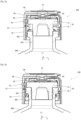
- the locking cap 100 when associated with the stopper 10, is capable of adopting two positions on the container 200: a first position, called intermediate holding, in which the stopper 10 is partially pushed into the neck 201 ( Figure 1a ). It is in this position that the container 200 can be subjected to a freeze-drying step, because the partial depression of the stopper 10 allows the evaporative flows to pass through the opening provided in the foot 12 of said stopper.
- the cap 100 associated with the stopper 10 can also adopt a second position, called locking, in which the stopper 10 is completely pushed in, and locked in the neck 201 by the cap 100 ( figure 1b ). In this position, the stopper 10 hermetically closes the container 200, the foot 12 being completely surrounded by the neck 201 of the container 200.
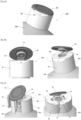
- the locking cap 100 comprises a capsule 40, an outer body 30 and a cage 20 ( figure 2a, figure 2b ).
- the outer body 30 is configured to completely surround the cage 20, so as to prevent any access to said cage 20 from the outside, when the cover 100 locks the cap 10 on the container 200.
- the external body 30 has a generally cylindrical shape; it is defined by an upper face 30a and a cylindrical wall 30b centered on a main axis z.
- the free end of the cylindrical wall 30b defines an opening, adapted to accommodate the cage 20, and the stopper 10 before the positioning of the cap 100 on the neck of the container 200.
- the external body 30 has a breakable strip 35, visible on the Figure 4b and the figure 4c .
- the breakable strip 35 extends from the upper face 30a to the free end of the cylindrical wall 30b. It may for example consist of a radial portion of the upper face 30a, continuing on a portion of the cylindrical wall 30b, said portions being delimited by a double groove at the level of which the thickness of the external body 30 is reduced.
- Capsule 40 ( Figure 2a ) is arranged on the upper face 30a of the external body 30 and secured to the breakable strip 35 at a first fixing zone F1 ( figure 1a, figure 1b , figure 2b ).
- the elements to be secured may include mechanical retaining means capable of cooperating to form the first fixing zone F1.
- the mechanical retaining means may in particular consist of a rim or shoulder, a dovetail system, etc. ( figure 2b ).
- the capsule 40 may comprise a tenon intended to pass through an orifice present on the upper face 30a of the external body 30, and in particular in the portion belonging to the breakable strip 35.
- the fixing between the capsule 40 and the external body 30 may be done by riveting. It may also be obtained by forming the capsule 40 and the external body 30 by an overmolding technique.
- the first fixing zone F1 may involve chemical adhesion between the materials of the elements to be secured.
- the capsule 40 and the external body 30 may be formed by an overmolding technique, from identical or different plastic materials, but capable of adhering to each other.
- the cage 20 of the locking cap 100 comprises an upper ring 21 and a plurality of branches 22 connected to the upper ring 21 and defining therewith a generally cylindrical shape of the cage 20, the central axis of which is the main axis z ( figure 3a, figure 3b ).
- the upper ring 21 is pressed against an internal surface of the upper face 30a.
- the plug 10 is intended to bear against the other side of the upper ring 21, as can be seen in the figure 1a And there figure 1b .
- the locking of the cage 20 in the body 30 is done, for example, by cooperation of lugs 221 in a complementary groove 301 arranged in the internal wall of the body 30 ( figure 2a, figure 2b ).
- the cage 20 also comprises a plurality of bridges 25, 26, each connecting two neighboring branches 22 together.
- the cage has six branches 22 and six bridges 25, but a different number could of course be implemented.
- first bridges 25 are positioned at or reach an intermediate altitude between the upper ring 21 and the end of the branches 22; second bridges 26 connect the ends of neighboring branches 22 and are positioned at or reach an altitude lower than the aforementioned intermediate altitude ( figure 3a, figure 3b ).
- first and second bridges (25, 26) are preferably an alternation of first and second bridges (25, 26) on the periphery of the cage 20.
- the first bridges 25 occupy between 20% and 40% of the perimeter of the cage 20, for example 30%; and the second bridges 26 occupy between 40% and 70% of said perimeter, for example 60%.
- the residual perimeter to reach 100% is occupied by the branches 22.
- each first bridge 25 is designed to provide an open space 251 between it and the collar 202, when the cap 100 is in its intermediate holding position ( figure 3b ).
- the cage 20 thus has open spaces 251, distributed around the perimeter of the cage 20, allowing efficient evacuation of evaporative flows during freeze-drying steps.
- the first bridges 25 can alternatively be devoid of the open space 251 (therefore be full up to the free end of the branches 22) or provided with a much more restricted space, not effective for evacuation of gas flow but useful, for example for mechanical reasons or for part design or even gripping.
- the cage 20 comprises a plurality of first tabs 23, each being supported by a first bridge 25.
- Each first tab 23 is flexible and inclined relative to the branches 22 towards the inside of the cage 20, at an angle of between 20° and 60°, advantageously around 45°, towards the upper ring 21.
- These first tabs 23 are intended to block the plug 10 inside the cage 20, against the upper ring 21, when the plug 10 is associated with the cap 100.
- the first tabs 23 flex to allow the head 11 of the plug 10 to pass when the latter is introduced into the cage 20, and come to block under the head 11, to prevent the plug 10 from being extracted from said cage 20.
- the stopper 10 remains firmly attached to the cover 100 and no accidental separation between the stopper 10 and the cover 100 can occur, in particular, when the cover 100 is in its intermediate holding position on the container 200.
- the cage 20 advantageously comprises a plurality of second tabs 24, each supported by a second bridge 26.
- Each second tab 24 is flexible and inclined relative to the branches 22 towards the inside of the cage 20, at an angle of between 20° and 60°, advantageously around 30°, in the direction of the upper ring 21.
- These second tabs 24 are intended to remain above the collar 202, slightly raised or in contact with it, when the cap 100 is in the intermediate holding position ( Figure 1a ). In this intermediate holding position, the second bridges 26 and the branches 22 are intended to at least partially surround the collar 202. This configuration allows for more stable and secure mechanical holding of the cap 10 - cover 100 assembly, during potential freeze-drying steps.
- the second tabs 24 are intended to rest under the collar 202 of the neck 201 of the container 200, when the cap 100 is in the locking position ( Figures 1b ). Indeed, when moving to the locked position, the cap 10 - cap 100 assembly will descend into/around the neck 201 of the container 200, so as to completely push the foot 12 of the cap 10 into the neck 201, until its head 11 rests on the collar 202. When pushing, the second tabs 24 flex and disappear to allow the collar 202 to pass, and come to block under the latter, thus locking the cap 10 on the container 200. Note that, in the locked position, the first tabs 23 disappear because they are resting against the peripheral edge of the collar 202. They therefore do not remain under the head 11 of the cap 10 and allow the latter to rest on the collar 202. The first bridges 25 then surround the peripheral edge of the collar 202.
- the cage 20 comprises at least one flexible member 27, one end of which is secured to a bridge 25, 26 and another end, free, is oriented towards the upper ring 21.
- the flexible member 27 is able to flex towards the outside of the cage 20. In the examples illustrated, it is secured to a second bridge 26 but this configuration is not limiting; it is entirely possible for the flexible member 27 to be supported by a first bridge 25.
- the flexible member 27 is furthermore adjacent to a fragile point 28 arranged in the bridge 25, 26 supporting said member 27.
- the fragile point 28 may correspond to a notch ( Figure 3a ) or to a partial or total split ( figure 3b ), arranged on said bridge 25,26. This fragile point 28 constitutes a privileged breaking point when a force is applied to said bridge 25,26, in particular via the flexible member 27.
- the flexible member 27 of the cage 20 is integral with the breakable strip 35 of the external body 30 at a second fixing zone F2 ( figure 2b ).
- the elements to be secured may comprise mechanical retaining means capable of cooperating to form the second attachment zone F2.
- the mechanical retaining means may consist of a rim, a shoulder 271 (arranged on the flexible member 27 to cooperate with a complementary hollow in the external body 30) or even a dovetail system, obtained by forming the flexible member 27 and the external body 30 using an overmolding technique.
- the second fixing zone F2 may involve chemical adhesion between the materials of the elements to be secured.
- the flexible member 27 and the external body 30 may be formed by an overmolding technique, from identical or different plastic materials, but capable of adhering to each other.
- the second fixing zone F2 is located, in altitude along the main axis z, between the upper face 30a of the external body 30 and a mid-height of the cylindrical wall 30b of the external body 30, which brings the advantages of a lever arm during the process of total removal of the locking cap 100.
- the second fixing zone F2 could alternatively be located at any altitude between the bridge 25, 26 supporting the flexible member 27 and the upper ring 21.
- the locking cap 100 is completely removable and therefore allows the removal of the cap 10 with a view to completely opening the container 200.
- a local gripping zone 43 is defined by the mutual shape of the capsule 40 and the body 30 in a peripheral part of the cap 100.
- This force is transmitted from the capsule 40 to the breakable strip 35, these two elements being integral ( Figure 4b ).
- the tearing force if sufficient, will induce a rupture between the breakable strip 35 and the rest of the external body 30 (for example, at the level of the double groove of reduced thickness) over the entire extent of the breakable strip 35 ( figure 4c ).
- a hinge or flexible articulation zone 32 can be arranged in the cylindrical wall 30b of the body 30, in a region diametrically opposite the portion of cylindrical wall 30b corresponding to the breakable strip 35; this facilitates the separation into two parts of the external body 30 and consequently its separation from the container 200.
- the capsule 40 and the breakable strip 35 remain integral with the flexible member 27 of the cage 20, at the level of the second fixing point F2 ( figure 4d ).
- a force to the capsule 40 - breakable strip 35 - flexible member 27 assembly oriented towards the outside of the cage 20, transmits a tearing stress at the fragile point 28 of the bridge 25, 26 supporting the flexible member 27.
- the fragile point 28 is a notch or a partial split
- the applied force causes the bridge 25, 26 to break 28' in the extension of said notch or partial split, and the deformation of the broken bridge 26' towards the outside of the cage 20.
- the fragile point 28 is a total split, the applied force induces the deformation of the bridge 26' and its separation towards the outside of the cage 20.
- the cage 20 can then be easily separated from the neck 201 of the container 200, leaving free access to the stopper 10 ( figure 4e ), which can, in turn, be removed to access the pharmaceutical product.
- the locking cap 100 Thanks to the characteristics of the locking cap 100 according to the invention, it is easy to remove it from the container 200 when the cap 10 must be opened to access the pharmaceutical product.
- the gripping of the capsule 40 is simple and ergonomic, and the fact that this capsule 40 is not only integral with the breakable strip 35 of the external body 30 but also with the flexible member 27 of the cage 20, facilitates the successive separation of the body 30 and the cage 20.
- the gripping of the capsule 40, then potentially of the capsule 40 and the breakable strip 35, is practical and well suited to operators wearing gloves, because the gripping surface is relatively large, compared to a flexible member 27 taken in isolation. The application of a force and its reproducibility are facilitated by this gripping ergonomics.
- the various elements forming the cover 100 according to the present invention are preferably produced by molding plastic materials compatible with the intended medical applications and other sterilization constraints.
- these three elements can advantageously be manufactured during one or more overmolding steps, to mold them and secure them directly to each other at the first F1 and second F2 fixing zones.
- the capsule 40 can be overmolded on the external body 30; then the body 30 - capsule 40 assembly can be overmolded on the cage 20.
- the overmolding steps could also be carried out in another order, by any method known from the state of the art.
- the cage 20, the outer body 30 and the capsule 32 may be formed from materials such as polycarbonate (PC), polypropylene (PP) or polybutylene terephthalate (PBT).
- the capsule 40 may be formed from flexible plastic materials such as, for example, polypropylene (PP), to facilitate its gripping. It may also be chosen to produce the outer body 30 from two different materials: a first material to form the breakable strip 35, said first material also being able to be chosen to form the capsule 40; and a second material to form the remainder of the outer body 30, possibly more rigid.
- the first material may be polypropylene
- the second material may be polybutylene terephthalate.
Landscapes
- Engineering & Computer Science (AREA)
- Mechanical Engineering (AREA)
- Health & Medical Sciences (AREA)
- Pharmacology & Pharmacy (AREA)
- Life Sciences & Earth Sciences (AREA)
- Animal Behavior & Ethology (AREA)
- General Health & Medical Sciences (AREA)
- Public Health (AREA)
- Veterinary Medicine (AREA)
- Closures For Containers (AREA)
- Medical Preparation Storing Or Oral Administration Devices (AREA)
Claims (11)
- Verschlusskappe (100) für einen Behälter (200) mit einem Hals, die dazu bestimmt ist, einen Stopfen (10) in dem Hals (201) des Behälters (200) zu blockieren, und umfassend:- einen Außenkörper (30), der durch eine Oberseite (30a) und eine zylindrische Wand (30b) definiert ist, die auf einer Hauptachse (z) zentriert ist, wobei der Außenkörper (30) einen teilbaren Streifen (35) aufweist, der sich von der Oberseite (30a) bis zu einem freien Ende der zylindrischen Wand (30b) erstreckt,- eine Kapsel (40), die auf der Oberseite (30a) angeordnet und mit dem teilbaren Streifen (35) fest verbunden ist,- ein Gehäuse (20), das in dem Außenkörper (30) eingeschlossen ist und dazu bestimmt ist, einen Flansch (202) des Halses (201) des Behälters (200) in einer Verschlussposition der Kappe (100) zu umgeben; wobei das Gehäuse (20) einen oberen Ring (21), wobei der Stopfen (10) dazu bestimmt ist, sich auf diesen zu stützen, wenn er in dem Gehäuse (20) angeordnet wird, eine Vielzahl von Schenkeln (22), die mit dem oberen Ring (21) verbunden sind und damit eine allgemeine zylindrische Form des Gehäuses (20) ausbilden, eine Vielzahl von Brücken (25,26), die jeweils zwei benachbarte Schenkel (22) miteinander verbinden, und ein flexibles Element (27), von dem ein Ende mit einer Brücke (25,26) fest verbunden ist und ein anderes freies Ende zu dem oberen Ring (21) hin ausgerichtet ist, vorweist, wobei das flexible Element (27) an eine zerbrechliche Stelle (28) der Brücke (25,26) angrenzt; wobei die Verschlusskappe (100) dadurch gekennzeichnet ist, dass das flexible Element (27) des Gehäuses (20) mit dem teilbaren Streifen (35) des Außenkörpers (30) fest verbunden ist.
- Verschlusskappe (100) nach dem vorstehenden Anspruch, wobei die zerbrechliche Stelle (28) einer Kerbe oder einem Schlitz entspricht, die/der an der Brücke (25,26) eingerichtet ist, die das flexible Element (27) trägt.
- Verschlusskappe (100) nach einem der vorstehenden Ansprüche, wobei:- die Kapsel (40) mit dem teilbaren Streifen (35) auf Höhe einer ersten Befestigungszone (F1) fest verbunden ist,- das flexible Element (27) mit dem teilbaren Streifen (35) auf Höhe einer zweiten Befestigungszone (F2) fest verbunden ist, und- die erste (F1) und/oder die zweite (F2) Befestigungszone(n) durch mechanische Haltemittel ausgebildet ist (sind), die an jedem fest zu verbindenden Element angeordnet sind und miteinander zusammenwirken.
- Verschlusskappe (100) nach einem der vorstehenden Ansprüche, wobei:- eine Kapsel (40) mit dem teilbaren Streifen (35) auf Höhe einer ersten Befestigungszone (F1) fest verbunden ist,- das flexible Element (27) mit dem teilbaren Streifen (35) auf Höhe einer zweiten Befestigungszone (F2) fest verbunden ist, und- die erste (F1) und/oder die zweite (F2) Befestigungszone(n) eine chemische Haftung zwischen den Materialien der fest zu verbindenden Elemente impliziert (implizieren).
- Verschlusskappe (100) nach einem der vorstehenden Ansprüche, wobei die mechanischen Haltemittel einen Rand, einen Absatz oder ein Schwalbenschwanzsystem umfassen.
- Verschlusskappe (100) nach einem der Ansprüche 3 bis 5, wobei sich die zweite Befestigungszone (F2) auf der Höhe entlang der Hauptachse (z) zwischen der Oberseite (30a) des Außenkörpers (30) und einer halben Höhe der zylindrischen Wand (30b) des Außenkörpers (30) befindet.
- Verschlusskappe (100) nach einem der vorstehenden Ansprüche, wobei:- der Außenkörper (30) aus einem ersten Material und einem zweiten Material erstellt wird, wobei das erste Material den teilbaren Streifen (35) ausbildet und das zweite Material den Rest des Außenkörpers (30) ausbildet,- die Kapsel (40) aus dem ersten Material erstellt ist.
- Verschlusskappe (100) nach einem der vorstehenden Ansprüche, wobei die Kapsel (40) aus Polypropylen ausgebildet ist.
- Verschlusskappe (100) nach einem der vorstehenden Ansprüche, wobei der Außenkörper (30) aus einem oder mehreren Materialien besteht, ausgewählt aus Polypropylen und Polybutylenterephthalat.
- Verschlusskappe (100) nach einem der vorstehenden Ansprüche, wobei das Gehäuse (20) aus Polycarbonat ausgebildet ist.
- Verfahren zum Herstellen einer Verschlusskappe (100) nach einem der vorstehenden Ansprüche, umfassend mindestens einen Überformungsschritt zum Formen und festen Verbinden miteinander:- der Kapsel (40) und des Außenkörpers (30) und- des Außenkörpers (30) und des Gehäuses (20).
Applications Claiming Priority (1)
| Application Number | Priority Date | Filing Date | Title |
|---|---|---|---|
| FR2214266A FR3144116B1 (fr) | 2022-12-22 | 2022-12-22 | coiffe de verrouillage sécable pour récipient à col |
Publications (3)
| Publication Number | Publication Date |
|---|---|
| EP4389634A1 EP4389634A1 (de) | 2024-06-26 |
| EP4389634B1 true EP4389634B1 (de) | 2025-02-26 |
| EP4389634C0 EP4389634C0 (de) | 2025-02-26 |
Family
ID=85462443
Family Applications (1)
| Application Number | Title | Priority Date | Filing Date |
|---|---|---|---|
| EP23213079.9A Active EP4389634B1 (de) | 2022-12-22 | 2023-11-29 | Abtrennbare verschlusskappe für einen behälter mit hals |
Country Status (12)
| Country | Link |
|---|---|
| US (1) | US12540014B2 (de) |
| EP (1) | EP4389634B1 (de) |
| JP (1) | JP2024091570A (de) |
| KR (1) | KR20240100235A (de) |
| CN (1) | CN118239119A (de) |
| CA (1) | CA3223342A1 (de) |
| ES (1) | ES3023684T3 (de) |
| FR (1) | FR3144116B1 (de) |
| IL (1) | IL308908A (de) |
| MX (1) | MX2023015003A (de) |
| TW (1) | TW202434506A (de) |
| ZA (1) | ZA202311147B (de) |
Families Citing this family (1)
| Publication number | Priority date | Publication date | Assignee | Title |
|---|---|---|---|---|
| EP4238887B1 (de) * | 2022-03-03 | 2024-11-06 | Inductio AG | Verschlusssystem für einen medikamentenbehälter sowie medikamentenbehälter mit einem verschlusssystem |
Family Cites Families (3)
| Publication number | Priority date | Publication date | Assignee | Title |
|---|---|---|---|---|
| FR2986782B1 (fr) | 2012-02-13 | 2014-03-07 | Raymond A & Cie | Dispositif de verrouillage de bouchon sur recipient a collerette, recipient a collerette obture par bouchon pourvu d'un tel dispositif de verrouillage |
| FR3098504B1 (fr) * | 2019-07-09 | 2021-06-04 | A Raymond Et Cie | coiffe de verrouillage pour récipient à col |
| FR3098505B1 (fr) | 2019-07-09 | 2021-06-04 | A Raymond Et Cie | coiffe de verrouillage sécable pour récipient à col |
-
2022
- 2022-12-22 FR FR2214266A patent/FR3144116B1/fr active Active
-
2023
- 2023-11-27 IL IL308908A patent/IL308908A/en unknown
- 2023-11-27 KR KR1020230167019A patent/KR20240100235A/ko active Pending
- 2023-11-28 TW TW112146082A patent/TW202434506A/zh unknown
- 2023-11-29 EP EP23213079.9A patent/EP4389634B1/de active Active
- 2023-11-29 ES ES23213079T patent/ES3023684T3/es active Active
- 2023-12-04 ZA ZA2023/11147A patent/ZA202311147B/en unknown
- 2023-12-12 CN CN202311709689.0A patent/CN118239119A/zh active Pending
- 2023-12-13 MX MX2023015003A patent/MX2023015003A/es unknown
- 2023-12-15 CA CA3223342A patent/CA3223342A1/fr active Pending
- 2023-12-20 US US18/390,265 patent/US12540014B2/en active Active
- 2023-12-21 JP JP2023215618A patent/JP2024091570A/ja active Pending
Also Published As
| Publication number | Publication date |
|---|---|
| TW202434506A (zh) | 2024-09-01 |
| ES3023684T3 (en) | 2025-06-02 |
| JP2024091570A (ja) | 2024-07-04 |
| US12540014B2 (en) | 2026-02-03 |
| ZA202311147B (en) | 2024-08-28 |
| CN118239119A (zh) | 2024-06-25 |
| EP4389634A1 (de) | 2024-06-26 |
| CA3223342A1 (fr) | 2024-06-22 |
| EP4389634C0 (de) | 2025-02-26 |
| IL308908A (en) | 2024-07-01 |
| US20240208697A1 (en) | 2024-06-27 |
| MX2023015003A (es) | 2024-06-24 |
| KR20240100235A (ko) | 2024-07-01 |
| FR3144116B1 (fr) | 2024-11-15 |
| FR3144116A1 (fr) | 2024-06-28 |
Similar Documents
| Publication | Publication Date | Title |
|---|---|---|
| EP3763634B1 (de) | Verschlusskappe für behälter mit hals | |
| EP3763635B1 (de) | Abtrennbare verschlusskappe für behälter mit hals | |
| EP0704251B1 (de) | Ring, Vorrichtung und Verfahren zum Befestigen einer Kappe an einem Behälter | |
| EP2643231B1 (de) | Stöpselvorrichtung für einen behälter und mit einer solchen vorrichtung ausgestatteter behälter | |
| EP2102071B1 (de) | Nachfüllungsverhinderungsvorrichtung für den hals eines gefässes | |
| FR3106339A1 (fr) | Coiffe de verrouillage pour recipient a col avec une capsule a pattes de fixation secables | |
| CA2908800C (fr) | Flacon de conditionnement de liquide | |
| EP0345173A1 (de) | Verschlussvorrichtung, bestehend aus einer Kappe und einem Originalitätsring, und Verfahren zu ihrer Herstellung | |
| EP0575272A1 (de) | Kunststofftube mit einem zerreissbaren Innenhütchen, diese Tube mit einer Kapsel und deren Anwendungen | |
| EP4389634B1 (de) | Abtrennbare verschlusskappe für einen behälter mit hals | |
| FR3004379A1 (fr) | Procede de fabrication d'un bouchon de fermeture du goulot d'un contenant, procede de bouchage d'un contenant par un bouchon fabrique selon un tel procede et bouchon fabrique selon un tel procede | |
| EP4410702B1 (de) | Bi-injizierter käfig einer phiolenverschlusskappe zur pharmazeutischen verwendung | |
| FR2508136A1 (fr) | Perfectionnement aux valves pour recipients aerosols | |
| CH419876A (fr) | Capsule de fermeture du type serti pour bouteilles et autres récipients munis d'un col | |
| EP4433378B1 (de) | Verschlusskappe für ein medizinisches gerät mit eignung für magnetischen griff | |
| EP4140916B1 (de) | Vorrichtung zum montieren einer verschlusskappe auf einem behälterhals | |
| EP3823764B1 (de) | Gehäuse für einen druckbehälter | |
| FR2890943A1 (fr) | Dispositif de bouchage d'un col de recipient, recipient equipe d'un tel dispositif et procede de fabrication d'un tel dispositif | |
| EP0642984A1 (de) | Originalitäts-Verschluss für Flaschen | |
| EP3760155B1 (de) | Doppelverpackung für gegenstand, der steril bleiben soll | |
| FR2964954A1 (fr) | Dispositif de securite pour bouteille contenant un liquide effervescent. | |
| FR2739360A1 (fr) | Capsule de bouchage anti-fraude | |
| FR3156642A1 (fr) | Tamis amovible pour réceptacle de produit cosmétique tel qu’un pot en verre, et pot muni d’un tel tamis | |
| FR2747105A1 (fr) | Recipient en verre a goulot, comportant un bouchon bloque dans le goulot | |
| FR3151309A1 (fr) | Dispositif de préhension d’une boucle muselet ou d’un ficelage |
Legal Events
| Date | Code | Title | Description |
|---|---|---|---|
| PUAI | Public reference made under article 153(3) epc to a published international application that has entered the european phase |
Free format text: ORIGINAL CODE: 0009012 |
|
| STAA | Information on the status of an ep patent application or granted ep patent |
Free format text: STATUS: REQUEST FOR EXAMINATION WAS MADE |
|
| 17P | Request for examination filed |
Effective date: 20231129 |
|
| AK | Designated contracting states |
Kind code of ref document: A1 Designated state(s): AL AT BE BG CH CY CZ DE DK EE ES FI FR GB GR HR HU IE IS IT LI LT LU LV MC ME MK MT NL NO PL PT RO RS SE SI SK SM TR |
|
| GRAP | Despatch of communication of intention to grant a patent |
Free format text: ORIGINAL CODE: EPIDOSNIGR1 |
|
| STAA | Information on the status of an ep patent application or granted ep patent |
Free format text: STATUS: GRANT OF PATENT IS INTENDED |
|
| RIC1 | Information provided on ipc code assigned before grant |
Ipc: B65D 51/24 20060101ALI20241018BHEP Ipc: B65D 51/00 20060101ALI20241018BHEP Ipc: B65D 45/30 20060101AFI20241018BHEP |
|
| INTG | Intention to grant announced |
Effective date: 20241107 |
|
| GRAS | Grant fee paid |
Free format text: ORIGINAL CODE: EPIDOSNIGR3 |
|
| GRAA | (expected) grant |
Free format text: ORIGINAL CODE: 0009210 |
|
| STAA | Information on the status of an ep patent application or granted ep patent |
Free format text: STATUS: THE PATENT HAS BEEN GRANTED |
|
| AK | Designated contracting states |
Kind code of ref document: B1 Designated state(s): AL AT BE BG CH CY CZ DE DK EE ES FI FR GB GR HR HU IE IS IT LI LT LU LV MC ME MK MT NL NO PL PT RO RS SE SI SK SM TR |
|
| REG | Reference to a national code |
Ref country code: GB Ref legal event code: FG4D Free format text: NOT ENGLISH |
|
| REG | Reference to a national code |
Ref country code: CH Ref legal event code: EP |
|
| REG | Reference to a national code |
Ref country code: DE Ref legal event code: R096 Ref document number: 602023002215 Country of ref document: DE |
|
| REG | Reference to a national code |
Ref country code: IE Ref legal event code: FG4D Free format text: LANGUAGE OF EP DOCUMENT: FRENCH |
|
| U01 | Request for unitary effect filed |
Effective date: 20250310 |
|
| U07 | Unitary effect registered |
Designated state(s): AT BE BG DE DK EE FI FR IT LT LU LV MT NL PT RO SE SI Effective date: 20250317 |
|
| REG | Reference to a national code |
Ref country code: ES Ref legal event code: FG2A Ref document number: 3023684 Country of ref document: ES Kind code of ref document: T3 Effective date: 20250602 |
|
| PG25 | Lapsed in a contracting state [announced via postgrant information from national office to epo] |
Ref country code: RS Free format text: LAPSE BECAUSE OF FAILURE TO SUBMIT A TRANSLATION OF THE DESCRIPTION OR TO PAY THE FEE WITHIN THE PRESCRIBED TIME-LIMIT Effective date: 20250526 |
|
| PG25 | Lapsed in a contracting state [announced via postgrant information from national office to epo] |
Ref country code: PL Free format text: LAPSE BECAUSE OF FAILURE TO SUBMIT A TRANSLATION OF THE DESCRIPTION OR TO PAY THE FEE WITHIN THE PRESCRIBED TIME-LIMIT Effective date: 20250226 |
|
| PG25 | Lapsed in a contracting state [announced via postgrant information from national office to epo] |
Ref country code: IS Free format text: LAPSE BECAUSE OF FAILURE TO SUBMIT A TRANSLATION OF THE DESCRIPTION OR TO PAY THE FEE WITHIN THE PRESCRIBED TIME-LIMIT Effective date: 20250626 Ref country code: NO Free format text: LAPSE BECAUSE OF FAILURE TO SUBMIT A TRANSLATION OF THE DESCRIPTION OR TO PAY THE FEE WITHIN THE PRESCRIBED TIME-LIMIT Effective date: 20250526 |
|
| PG25 | Lapsed in a contracting state [announced via postgrant information from national office to epo] |
Ref country code: HR Free format text: LAPSE BECAUSE OF FAILURE TO SUBMIT A TRANSLATION OF THE DESCRIPTION OR TO PAY THE FEE WITHIN THE PRESCRIBED TIME-LIMIT Effective date: 20250226 |
|
| PG25 | Lapsed in a contracting state [announced via postgrant information from national office to epo] |
Ref country code: GR Free format text: LAPSE BECAUSE OF FAILURE TO SUBMIT A TRANSLATION OF THE DESCRIPTION OR TO PAY THE FEE WITHIN THE PRESCRIBED TIME-LIMIT Effective date: 20250527 |
|
| PG25 | Lapsed in a contracting state [announced via postgrant information from national office to epo] |
Ref country code: SM Free format text: LAPSE BECAUSE OF FAILURE TO SUBMIT A TRANSLATION OF THE DESCRIPTION OR TO PAY THE FEE WITHIN THE PRESCRIBED TIME-LIMIT Effective date: 20250226 |
|
| PG25 | Lapsed in a contracting state [announced via postgrant information from national office to epo] |
Ref country code: CZ Free format text: LAPSE BECAUSE OF FAILURE TO SUBMIT A TRANSLATION OF THE DESCRIPTION OR TO PAY THE FEE WITHIN THE PRESCRIBED TIME-LIMIT Effective date: 20250226 |
|
| PG25 | Lapsed in a contracting state [announced via postgrant information from national office to epo] |
Ref country code: SK Free format text: LAPSE BECAUSE OF FAILURE TO SUBMIT A TRANSLATION OF THE DESCRIPTION OR TO PAY THE FEE WITHIN THE PRESCRIBED TIME-LIMIT Effective date: 20250226 |
|
| U20 | Renewal fee for the european patent with unitary effect paid |
Year of fee payment: 3 Effective date: 20251127 |
|
| PLBE | No opposition filed within time limit |
Free format text: ORIGINAL CODE: 0009261 |
|
| STAA | Information on the status of an ep patent application or granted ep patent |
Free format text: STATUS: NO OPPOSITION FILED WITHIN TIME LIMIT |
|
| PGFP | Annual fee paid to national office [announced via postgrant information from national office to epo] |
Ref country code: IE Payment date: 20251121 Year of fee payment: 3 |
|
| PGFP | Annual fee paid to national office [announced via postgrant information from national office to epo] |
Ref country code: ES Payment date: 20251229 Year of fee payment: 3 |
|
| 26N | No opposition filed |
Effective date: 20251127 |