EP4388360B1 - Linsenausrichtungssystem mit mehreren freiheitsgraden - Google Patents
Linsenausrichtungssystem mit mehreren freiheitsgraden Download PDFInfo
- Publication number
- EP4388360B1 EP4388360B1 EP22786211.7A EP22786211A EP4388360B1 EP 4388360 B1 EP4388360 B1 EP 4388360B1 EP 22786211 A EP22786211 A EP 22786211A EP 4388360 B1 EP4388360 B1 EP 4388360B1
- Authority
- EP
- European Patent Office
- Prior art keywords
- lens body
- axis
- end effectors
- plane
- engagement
- Prior art date
- Legal status (The legal status is an assumption and is not a legal conclusion. Google has not performed a legal analysis and makes no representation as to the accuracy of the status listed.)
- Active
Links
Images


Classifications
-
- G—PHYSICS
- G02—OPTICS
- G02B—OPTICAL ELEMENTS, SYSTEMS OR APPARATUS
- G02B7/00—Mountings, adjusting means, or light-tight connections, for optical elements
- G02B7/003—Alignment of optical elements
- G02B7/005—Motorised alignment
-
- G—PHYSICS
- G02—OPTICS
- G02B—OPTICAL ELEMENTS, SYSTEMS OR APPARATUS
- G02B7/00—Mountings, adjusting means, or light-tight connections, for optical elements
- G02B7/02—Mountings, adjusting means, or light-tight connections, for optical elements for lenses
- G02B7/023—Mountings, adjusting means, or light-tight connections, for optical elements for lenses permitting adjustment
-
- H—ELECTRICITY
- H04—ELECTRIC COMMUNICATION TECHNIQUE
- H04N—PICTORIAL COMMUNICATION, e.g. TELEVISION
- H04N23/00—Cameras or camera modules comprising electronic image sensors; Control thereof
- H04N23/50—Constructional details
- H04N23/55—Optical parts specially adapted for electronic image sensors; Mounting thereof
Definitions
- Various embodiments relate generally to lens alignment.
- Sensors may include receivers. Sensors may include emitters. In some sensors, a receiver may receive a reflection of a signal emitted by an emitter. The emitter may, for example, emit an electromagnetic signal. The electromagnetic signal may, for example, include an optical signal. The receiver may, for example, generate detection signal(s) in response to receiving an electromagnetic signal. The electromagnetic signal may, for example, include an optical signal. The receiver may, for example, include a photoelectric detector. In some sensors, a receiver may include a photoelectric detection array.
- a sensor may be at least partially disposed in a housing.
- the housing may, for example, provide protection to components of the sensor.
- the housing may protect an emitter and/or receiver of the sensor.
- the housing may be two pieces. At least one piece of the housing may, for example, be optically translucent.
- Apparatus and associated methods relate to a lens alignment system having opposing end effectors configured to control a position of a rigid lens body with respect to a plane.
- each of the opposing end effectors may engage a corresponding receptacle on respective opposite faces of the lens body.
- Each of the end effectors may, for example, frictionally contact each of the corresponding receptacles within a respective portion of each of at least two contact regions.
- each of the contact regions may, for example, lie on opposite sides of an axis of rotation that extends between the end effectors.
- the lens body In response to at least a predetermined minimum net moment applied to the lens body, the lens body may, for example, be rotatable about the axis of rotation.
- Various embodiments may advantageously enable precise and/or rapid positioning of the lens body in the plane.
- Various embodiments may achieve one or more advantages. For example, some embodiments may advantageously rotate to accommodate variations in a lens body and/or housing.
- a lens body may advantageously float in an axis substantially orthogonal to the positioning plane in response to interaction between an engagement surface of the lens body and a receiving surface of a housing.
- one or more degrees of freedom e.g., rotational, linear
- complimenting engagement surfaces configured to auto-align the lens body along an axis may advantageously reduce or eliminate requirements of an operator biasing a lens body to a specific corner.
- Various embodiments may advantageously eliminate a requirement of force feedback to avoid overdriving an alignment machine.
- Some embodiments may advantageously reduce uncertainty in a measuring system (e.g., of a position of the lens body relative to a mounting surface).
- Various embodiments may advantageously increase speed of alignment of a lens body relative to a mounting surface (e.g., of a housing).
- a lens alignment system (LAS) is introduced with reference to FIGS. 1-4 .
- that introduction leads into a description with reference to FIGS. 5-8 of some exemplary geometry relating to an end effector and lens body of the LAS.
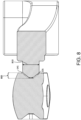
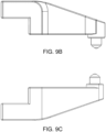
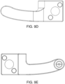
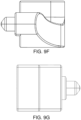
- Third, with reference to FIGS. 9A-9G an exemplary end effector is disclosed.
- the document discusses further embodiments, exemplary applications and aspects relating to lens alignment systems.
- FIG. 1 depicts an exemplary lens alignment system (LAS) employed in an illustrative use-case scenario.
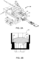
- FIG. 2A depicts a closeup view of the LAS in the illustrative use-case scenario.
- FIG. 2B depicts a cross-section view of an exemplary lens body in an exemplary housing.
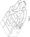
- FIG. 3 depicts the exemplary LAS in an isolated view including exemplary end effectors mounted to an actuator module and engaging the lens body.
- FIG. 4 depicts the exemplary end effectors engaging the lens body.
- the alignment system 120 includes opposing end effectors 130. Each end effector is provided with a distal engagement surface 135. When the opposing end effectors 130 are operated towards each other along the X axis, the respective distal engagement surfaces 135 engage corresponding receiver receptacles 140 in opposing faces of the lens body 105. Each of the corresponding receiver receptacles 140 is provided with an engagement surface 141. Accordingly, the alignment system 120 may operate the opposing end effectors 130 to position the lens body 105 in the first plane (e.g., the X-Y plane).
- the first plane e.g., the X-Y plane
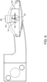
- FIG. 5 and FIG. 6 depict closeups views of the isolated configuration depicted in FIG. 4 with one of the end effectors removed to view a corresponding receiver receptacle.
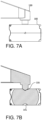
- FIG. 7A depicts a top view and
- FIG. 7B and FIG. 8 depict cross-section views of the configuration depicted in FIG. 5 .
- the receiver receptacles 140 have a width 605 (extending in the plane P L in a direction along the axis X L ) and a height 610.
- the width 605 defines a maximum width of the receiver receptacles 140.
- the width 605 is the distance between the parallel line segments.
- the height 610 defines a maximum height of the receiver receptacles 140.
- the height 610 defines is greater than the width 605 by the length 505.
- the length 505 in a Z L axis (orthogonal to the P L ) of the corresponding engagement surface 141 may, for example, define a degree of freedom of the lens body 105 relative to the opposing end effectors 130 when the distal engagement surfaces 135 engage the corresponding engagement surfaces 141.
- the distal engagement surface 135 is substantially configured as a conical frustum.
- the distal engagement surface 135 has an outer (e.g., maximum) diameter 810.
- a length of the distal engagement surface 135 along the A ⁇ axis may, for example, be substantially equal to the length 805.
- An angle of the distal engagement surface 135 relative to the A ⁇ may, as depicted, be substantially equal to an angle of the corresponding engagement surface 141 relative to the A ⁇ .
- the opposing end effectors 130 and the corresponding receiver receptacles 140 may each engage along two tangent lines in the plane P E .
- the length 505 of the corresponding engagement surface 141 may, for example, provide a range of adjustment in the Z axis (e.g., the Z L axis) of the lens body 105 relative to the opposing end effectors 130.
- FIG. 9A , FIG. 9B , FIG. 9C , FIG. 9D , FIG. 9E , FIG. 9F, and FIG. 9G depict an exemplary end effector.
- the depicted end effector may be a first of a pair of opposing end effectors (e.g., as disclosed at least with reference to FIGS. 1-8 ).
- a second of the pair of opposing end effectors may, for example, be (substantially) a mirror image of the depicted end effector.
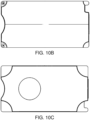
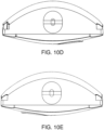
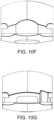
- FIG. 10A , FIG. 10B , FIG. 10C , FIG. 10D , FIG. 10E , FIG. 10F, and FIG. 10G depict an exemplary lens body.
- the depicted lens body may, for example, be the lens body disclosed at least with reference to FIGS. 1-8 .
- an X-Y positioning plane of opposing end effectors may be positioned such that, when the end effectors engage the lens body, an engagement surface of the lens body is lifted slightly (e.g., microns, less than 1/8 inch, less than 0.1 inch, less than 0.05 inch, less than 0.01 inch) above a receiving surface.
- conical engagement surfaces may be configured such that engagement of the end effectors in corresponding receiver receptacles centers the lens body along an axis passing through the end effectors (e.g., A ⁇ ).
- the distal engagement surface 135 and the corresponding engagement surface 141 may be configured to self-center the lens body 105 in the X-Y plane relative to the opposing end effectors 130.
- a housing may include a circuit board.
- a lens alignment system may be configured to position the lens body over an emitter and/or receiver element on a circuit board.
- a lens body may be coupled to a housing (e.g., after positioning) by a dispensing element (e.g., needle) dropping an adhesive (e.g., liquid) at one or more target points.
- a dispensing element e.g., needle
- an adhesive e.g., liquid
- the adhesive may flow between an engagement surface (e.g., engagement surface 145) and a receiving surface (e.g., receiving surface 150).
- the adhesive may cure (e.g., by photopolymerization).
- complimenting engagement surfaces may be configured to auto-align the lens body along an axis (e.g., A ⁇ ).
- a position of the lens body may, for example, be known based on the auto-alignment.
- various embodiments may advantageously reduce or eliminate requirements of an operator biasing a lens body to a specific corner.
- Various embodiments may advantageously eliminate a requirement of force feedback to avoid overdriving an alignment machine (e.g., because the position of the lens body is known based on monitoring a (commanded) position of the opposing end effectors 130).
- Some embodiments may advantageously reduce uncertainty in a measuring system (e.g., of a position of the lens body relative to a mounting surface).
- Various embodiments may advantageously increase speed of alignment of a lens body relative to a mounting surface (e.g., of a housing).
- the end effectors may, for example, be configured to reduce friction between engagement surfaces of the end effectors and the lens body.
- the distal engagement surface 135 may include (poly)tetrafluoroethylene.
- the distal engagement surface 135 may, for example, include oil-impregnated brass.
- the distal engagement surface 135 may, for example, be coated (e.g., permanently, semi-permanently, temporarily) to reduce stick-slip between the distal engagement surface 135 and the corresponding engagement surface 141.
- the lens body may, for example, include acrylic (e.g., to achieve a desired index of refraction).
- the end effectors may, for example, be controlled by pneumatic actuators.
- the end effectors may, for example, be controlled by rotary actuators (e.g., via leadscrews, via ballscrews).
- the end effectors may be operably coupled to at least one rotary (electric) motor.
- the motor(s) may, for example, be configured as a servo motor.
- the motor may, for example, be operated in a torque control mode such that a maximum moment is applied to the end effectors.
- the end effector may, for example, have a known weight (e.g., corresponding to a known moment relative to the motor).
- the motor may, for example, apply a moment to the end effector just less than (e.g., 1.99 ft-lbs when the effector applies two ft-lbs of moment to the motor).
- Some embodiments may, for example, detect contact of the end effectors with the lens body.
- the contact may, for example, be determined by torque sensing in an actuator operably coupled to the effector).
- the contact may, for example, be determined by a distance measurement sensor.
- the contact may, for example, be determined by force feedback.
- some systems may be configured to retract the end effectors slightly (e.g., to reduce a force of contact).
- Some systems may, for example, advance the end effectors slightly (e.g., to achieve a minimum force of contact with the lens body).
- a position of the lens body may, for example, be monitored by a distance sensor.
- a laser distance sensor(s) may monitor placement of the lens body.
- the ball joint may, for example, provide a linear degree of freedom (e.g., Z) of the engagement module relative to the end effector in a direction substantially orthogonal to a plane of engagement of the lens body (e.g., a plane containing the engagement surface 145).
- a linear degree of freedom e.g., Z
- Some such embodiments may, for example, advantageously avoid interference of an inwardly protruding receiver receptacle with an optical field (e.g., of an emitter and/or receiver).
- Various such embodiments may, for example, reduce manufacturing costs of a lens body.
- an engagement feature of the lens body may, for example, be configured as a cavity in the lens body (e.g., a blind cavity, an aperture).
- the cavity may, for example, define an engagement boundary (e.g., a boundary of an aperture).
- a distal engagement surface of the end effector may be configured to engage the engagement boundary.
- the engagement boundary may, for example, provide a rotational degree of freedom (e.g., ⁇ ) relative to the end effector.
- the engagement boundary may, for example, provide a linear degree of freedom (e.g., Z) relative to the end effector.
- a receiver receptacle may be provided in an alignment module.
- the alignment module may, for example, releasably couple to a lens body.
- the alignment module may be provided with engagement features configured to releasably engage mating engagement features of the lens body.
- the mating engagement features may, for example, align the alignment module relative to the lens body.
- the end effectors may, for example, be configured to engage the receiver receptacles of the alignment module.
- a lens alignment system may include opposing end effectors configured to control a position of a rigid lens body with respect to a first plane by engaging, with each of the end effectors, a corresponding receptacle on respective opposite faces of the lens body.
- Each of the end effectors may frictionally contact each of the corresponding receptacles within a respective portion of each of at least two contact regions that, during the engagement, lie on opposite sides of an axis of rotation that extends between the end effectors,
- the lens body is rotatable about the axis of rotation.
- Rotation of the lens body about the axis of rotation may impart a change in a location of each of the respective portions within each of the respective contact regions.
Landscapes
- Physics & Mathematics (AREA)
- General Physics & Mathematics (AREA)
- Optics & Photonics (AREA)
- Engineering & Computer Science (AREA)
- Multimedia (AREA)
- Signal Processing (AREA)
- Optical Couplings Of Light Guides (AREA)
- Manipulator (AREA)
Claims (13)
- Linsenkörperausrichtungs-System, aufweisend:gegenüberliegende Endeffektoren (130), die ausgebildet sind, eine Position eines Ziellinsenkörpers (105) in Bezug auf eine erste Ebene zu steuern durch reibschlüssiges in Eingriff nehmen einer entsprechenden Aufnahme (140) von zumindest zwei Aufnahmen (140) auf jeweiligen gegenüberliegenden Flächen des Linsenkörpers (105) an gegenüberliegenden Enden einer Drehachse (Aθ), die sich zwischen den Endeffektoren (130) erstreckt, durch jeden der Endeffektoren (130),wobei:jeder der gegenüberliegenden Endeffektoren (130) mindestens eine distale Eingriffsfläche (135) aufweist, die durch einen konischen Kegelstumpf (141) definiert und ausgebildet ist, die zugehörige Aufnahme innerhalb eines jeweiligen Abschnitts von jedem von mindestens zwei Kontaktbereichen (141), die während des Eingriffs auf gegenüberliegenden Seiten der Drehachse (Aθ) liegen, die sich zwischen den Endeffektoren (130) erstreckt, reibschlüssig zu berühren,und die gegenüberliegenden Endeffektoren (130) ausgebildet sind, selektiv aufeinander zu betätigt werden zu können, um die Kontaktbereiche der zugehörigen Aufnahmen des Linsenkörpers (105) reibschlüssig zu berühren,so dass ein vorbestimmtes minimales Nettomoment durch den reibschlüssigen Eingriff bestimmt wird,so dass der Linsenkörper (105) als Reaktion auf ein Ausüben mindestens des vorbestimmten minimalen Nettomoments auf den Linsenkörper (105) relativ zu den Endeffektoren (130) um die Drehachse drehbar ist.
- System nach Anspruch 1, wobei eine Drehung des Linsenkörpers (105) um die Drehachse eine Änderung einer Lage jedes der jeweiligen Abschnitte innerhalb jedem der jeweiligen Kontaktbereiche bewirkt; oder
wobei eine Drehung des Linsenkörpers (105) um die Drehachse in Reaktion auf einen Momentarm induziert wird, der einem Kontakt zwischen dem Linsenkörper (105) und einer Aufnahmefläche entspricht. - System nach Anspruch 1, wobei:jeder der mindestens zwei Kontaktbereiche eine Breite um eine zweite Achse besitzt, wobei die zweite Achse während des Eingriffs im Wesentlichen orthogonal zu der Drehachse und im Wesentlichen parallel zu der ersten Ebene ist,so dass der Linsenkörper (105) als Reaktion auf mindestens eine vorbestimmte Mindestkraft, die auf den Linsenkörper (105) in einer Richtung im Wesentlichen orthogonal zu der ersten Ebene ausgeübt wird, in einer Richtung orthogonal zu der ersten Ebene gemäß einer Wechselwirkung des Linsenkörpers (105) mit einer Aufnahmefläche schwimmen kann.
- System nach Anspruch 3, wobei die Aufnahmefläche mindestens ein Teil eines Gehäuses ist.
- System nach Anspruch 1, zudem aufweisend mindestens ein Betätigungsmodul, das betriebsfähig mit den Endeffektoren (130) gekoppelt ist, wobei das mindestens eine Betätigungsmodul ausgebildet ist, die Endeffektoren (130) so zu betätigen, dass während des Eingriffs eine Reibungskraftkomponente einer Wechselwirkung zwischen dem Linsenkörper (105) und einer Aufnahmefläche geringer ist als ein vorbestimmtes maximales Reibungsniveau; oder
wobei sich die zugehörigen Aufnahmen jeweils von der zugehörigen Fläche des Linsenkörpers (105) in den Linsenkörper (105) erstrecken. - System nach Anspruch 1, wobei die distale Eingriffsfläche jedes Endeffektors (130) ausgebildet ist, in den Kontaktabschnitt einzugreifen und
die distale Eingriffsfläche einen im Wesentlichen kreisförmigen Querschnitt in Bezug auf die Drehachse besitzt. - System nach Anspruch 6, wobei die distale Eingriffsfläche durch einen konischen Kegelstumpf (141) begrenzt ist.
- System nach Anspruch 7, wobei ein Radius des Querschnitts in einer distalen Richtung entlang der Drehachse relativ zu dem zugehörigen Endeffektor (130) im Wesentlichen monoton abnimmt.
- System nach Anspruch 1, wobei:ein Querschnitt jeder der zugehörigen Aufnahmen in Bezug auf die Drehachse durch einen Querschnitt definiert ist, der zwei Halbkreise aufweist, die um eine Ebene gespiegelt sind, die während des Eingriffs im Wesentlichen parallel zu der ersten Ebene ist,die beiden Halbkreise durch zwei im Wesentlichen parallele Liniensegmente verbunden sind unddie Liniensegmente durch einen Abstand voneinander getrennt sind, der einem Durchmesser der Halbkreise entspricht, und jeweils im Wesentlichen tangential zu beiden der Halbkreise sind.
- System nach Anspruch 9, wobei die Liniensegmente während des Eingriffs im Wesentlichen orthogonal zu der ersten Ebene sind.
- System nach Anspruch 1, wobei jede der gegenüberliegenden Flächen mit einer Mehrzahl von Aufnahmen versehen ist.
- System nach Anspruch 1, wobei der Eingriff den Linsenkörper (105) in einer Ebene parallel zu der ersten Ebene verschiebt.
- System nach Anspruch 3, wobei die gegenüberliegenden Endeffektoren (130) jeweils verschiebbar in den Linsenkörper (105) eingreifen, so dass der Linsenkörper (105) in einer Richtung orthogonal zu der ersten Ebene entsprechend einer Wechselwirkung des Linsenkörpers (105) mit einer Aufnahmefläche schwimmen kann; oder
wobei die gegenüberliegenden Endeffektoren (130) jeweils in den Linsenkörper (105) eingreifen, so dass, wenn distale Eingriffsflächen der gegenüberliegenden Endeffektoren (130) in zugehörige distale Eingriffsflächen des Linsenkörpers (105) eingreifen, Abmessungen der distalen Eingriffsflächen der gegenüberliegenden Endeffektoren (130) und der zugehörigen distalen Eingriffsflächen des Linsenkörpers (105) einen Freiheitsgrad in einer ersten Achse in der ersten Ebene aufweisen.
Applications Claiming Priority (2)
| Application Number | Priority Date | Filing Date | Title |
|---|---|---|---|
| US17/447,905 US12153279B2 (en) | 2021-09-16 | 2021-09-16 | Lens alignment system with multiple degrees of freedom |
| PCT/US2022/074777 WO2023044209A1 (en) | 2021-09-16 | 2022-08-10 | Lens alignment system with multiple degrees of freedom |
Publications (3)
| Publication Number | Publication Date |
|---|---|
| EP4388360A1 EP4388360A1 (de) | 2024-06-26 |
| EP4388360C0 EP4388360C0 (de) | 2025-07-02 |
| EP4388360B1 true EP4388360B1 (de) | 2025-07-02 |
Family
ID=83598462
Family Applications (1)
| Application Number | Title | Priority Date | Filing Date |
|---|---|---|---|
| EP22786211.7A Active EP4388360B1 (de) | 2021-09-16 | 2022-08-10 | Linsenausrichtungssystem mit mehreren freiheitsgraden |
Country Status (5)
| Country | Link |
|---|---|
| US (1) | US12153279B2 (de) |
| EP (1) | EP4388360B1 (de) |
| CN (1) | CN117999503A (de) |
| MX (1) | MX2024003393A (de) |
| WO (1) | WO2023044209A1 (de) |
Family Cites Families (21)
| Publication number | Priority date | Publication date | Assignee | Title |
|---|---|---|---|---|
| CA2273729A1 (en) | 1998-07-14 | 2000-01-14 | Bayer Corporation | Robotics for transporting containers and objects within an automated analytical instrument and service tool for servicing robotics |
| JP4229760B2 (ja) | 2003-05-27 | 2009-02-25 | 三菱電機株式会社 | 撮像装置の焦点調整装置 |
| US7796187B2 (en) | 2004-02-20 | 2010-09-14 | Flextronics Ap Llc | Wafer based camera module and method of manufacture |
| JP3766835B2 (ja) | 2004-09-10 | 2006-04-19 | シャープ株式会社 | レンズ系調整装置およびそれを用いたレンズ系調整方法 |
| JP4667952B2 (ja) | 2005-04-28 | 2011-04-13 | 日本電産コパル株式会社 | カメラモジュールの調整装置及び調整方法 |
| JP5198295B2 (ja) | 2008-01-15 | 2013-05-15 | 富士フイルム株式会社 | 撮像素子の位置調整方法、カメラモジュール製造方法及び装置、カメラモジュール |
| US8063975B2 (en) | 2008-10-29 | 2011-11-22 | Jabil Circuit, Inc. | Positioning wafer lenses on electronic imagers |
| US8335411B2 (en) | 2008-11-11 | 2012-12-18 | Ultra Communications, Inc. | Fiber optic bi-directional coupling lens |
| US8786713B1 (en) | 2013-03-14 | 2014-07-22 | Automation Engineering, Inc. | Fixture for aligning auto-focus lens assembly to camera sensor |
| JP6328799B2 (ja) * | 2015-01-19 | 2018-05-23 | シャープ株式会社 | カメラモジュールの製造方法及びカメラモジュール |
| TWI589946B (zh) | 2015-08-18 | 2017-07-01 | 群光電子股份有限公司 | 鏡頭調焦方法與光學模組 |
| US9869833B2 (en) | 2015-10-02 | 2018-01-16 | Avago Technologies General Ip (Singapore) Pte. Ltd. | Optical receiver using a photodetector with a self-aligned lens |
| CN107324041B (zh) | 2016-04-29 | 2019-11-26 | 上海微电子装备(集团)股份有限公司 | 用于片盒夹持的机械手及自动片盒搬运装置 |
| KR101724678B1 (ko) | 2016-09-30 | 2017-04-10 | 엘지이노텍 주식회사 | 카메라 모듈 및 카메라 모듈의 제조 방법 |
| JP6845671B2 (ja) | 2016-11-30 | 2021-03-24 | 川崎重工業株式会社 | 部品実装装置及びその制御方法 |
| TWI639029B (zh) | 2017-04-10 | 2018-10-21 | 大立光電股份有限公司 | 含有塑膠透鏡的成像透鏡組、成像鏡頭模組及電子裝置 |
| KR102072811B1 (ko) * | 2017-06-16 | 2020-03-02 | 삼성전기주식회사 | 카메라 모듈 |
| KR102067069B1 (ko) * | 2017-06-16 | 2020-01-16 | 삼성전기주식회사 | 카메라 모듈 |
| WO2019138589A1 (ja) | 2018-01-15 | 2019-07-18 | シャープ株式会社 | レンズユニット、撮像装置、車両周辺監視システム、撮像装置の組立治具、および撮像装置の組立方法 |
| US11025807B1 (en) | 2019-12-02 | 2021-06-01 | Adasky, Ltd. | System and method for optical alignment and calibration of an infrared camera lens |
| EP4468076A4 (de) * | 2022-05-27 | 2025-05-28 | Samsung Electronics Co., Ltd | Kameramodul und mobile elektronische vorrichtung damit |
-
2021
- 2021-09-16 US US17/447,905 patent/US12153279B2/en active Active
-
2022
- 2022-08-10 WO PCT/US2022/074777 patent/WO2023044209A1/en not_active Ceased
- 2022-08-10 MX MX2024003393A patent/MX2024003393A/es unknown
- 2022-08-10 EP EP22786211.7A patent/EP4388360B1/de active Active
- 2022-08-10 CN CN202280062787.7A patent/CN117999503A/zh active Pending
Also Published As
| Publication number | Publication date |
|---|---|
| EP4388360C0 (de) | 2025-07-02 |
| CA3231775A1 (en) | 2023-03-23 |
| WO2023044209A1 (en) | 2023-03-23 |
| EP4388360A1 (de) | 2024-06-26 |
| MX2024003393A (es) | 2024-06-11 |
| US12153279B2 (en) | 2024-11-26 |
| US20230083301A1 (en) | 2023-03-16 |
| CN117999503A (zh) | 2024-05-07 |
Similar Documents
| Publication | Publication Date | Title |
|---|---|---|
| EP0663066B1 (de) | Optischer wegsensor | |
| CN102252639B (zh) | 测量系统 | |
| US6898487B2 (en) | Specimen sensing and edge gripping end effector | |
| CN102261900A (zh) | 测量系统 | |
| US7047826B2 (en) | Force sensors | |
| US4899048A (en) | Focused optical beam encoder of position | |
| EP0125775A2 (de) | Bewegungskontrolle für einen Roboterarm | |
| JPH05240209A (ja) | 流体サーボ弁 | |
| CN107206589B (zh) | 确定机器人关节的校准位置 | |
| EP4388360B1 (de) | Linsenausrichtungssystem mit mehreren freiheitsgraden | |
| CA3231775C (en) | Lens alignment system with multiple degrees of freedom | |
| US6420694B1 (en) | Steerable retroreflective system and method | |
| US4156130A (en) | Joystick mechanism | |
| Monfaredi et al. | Design of a decoupled MRI-compatible force sensor using fiber Bragg grating sensors for robot-assisted prostate interventions | |
| JPH0327044B2 (de) | ||
| EP1214632A1 (de) | Maschinenanlage mit optischer endpunktregelung | |
| US20030048448A1 (en) | Automated apparatus for testing optical filters | |
| US20030048455A1 (en) | Goniometer | |
| US7065892B2 (en) | Method and apparatus for calibrating a vision system to a parts handling device | |
| US20240181632A1 (en) | Robot drive module | |
| US4484854A (en) | Robotic height sensor in laterally compliant probe | |
| US5664033A (en) | Remote fiber test system using a non-blocking N×N mechanical fiber optical switch | |
| KR100279130B1 (ko) | 광센서를 이용한 위치결정장치를 구비한 병렬형 회전 및 병진운동 테이블 | |
| CN114680953B (zh) | 用于操纵手术工具的医疗装置 | |
| US20030038223A1 (en) | Flexure |
Legal Events
| Date | Code | Title | Description |
|---|---|---|---|
| STAA | Information on the status of an ep patent application or granted ep patent |
Free format text: STATUS: UNKNOWN |
|
| STAA | Information on the status of an ep patent application or granted ep patent |
Free format text: STATUS: THE INTERNATIONAL PUBLICATION HAS BEEN MADE |
|
| PUAI | Public reference made under article 153(3) epc to a published international application that has entered the european phase |
Free format text: ORIGINAL CODE: 0009012 |
|
| STAA | Information on the status of an ep patent application or granted ep patent |
Free format text: STATUS: REQUEST FOR EXAMINATION WAS MADE |
|
| 17P | Request for examination filed |
Effective date: 20240322 |
|
| AK | Designated contracting states |
Kind code of ref document: A1 Designated state(s): AL AT BE BG CH CY CZ DE DK EE ES FI FR GB GR HR HU IE IS IT LI LT LU LV MC MK MT NL NO PL PT RO RS SE SI SK SM TR |
|
| DAV | Request for validation of the european patent (deleted) | ||
| DAX | Request for extension of the european patent (deleted) | ||
| GRAP | Despatch of communication of intention to grant a patent |
Free format text: ORIGINAL CODE: EPIDOSNIGR1 |
|
| STAA | Information on the status of an ep patent application or granted ep patent |
Free format text: STATUS: GRANT OF PATENT IS INTENDED |
|
| INTG | Intention to grant announced |
Effective date: 20250214 |
|
| GRAS | Grant fee paid |
Free format text: ORIGINAL CODE: EPIDOSNIGR3 |
|
| GRAA | (expected) grant |
Free format text: ORIGINAL CODE: 0009210 |
|
| STAA | Information on the status of an ep patent application or granted ep patent |
Free format text: STATUS: THE PATENT HAS BEEN GRANTED |
|
| AK | Designated contracting states |
Kind code of ref document: B1 Designated state(s): AL AT BE BG CH CY CZ DE DK EE ES FI FR GB GR HR HU IE IS IT LI LT LU LV MC MK MT NL NO PL PT RO RS SE SI SK SM TR |
|
| REG | Reference to a national code |
Ref country code: GB Ref legal event code: FG4D |
|
| REG | Reference to a national code |
Ref country code: CH Ref legal event code: EP |
|
| REG | Reference to a national code |
Ref country code: DE Ref legal event code: R096 Ref document number: 602022017035 Country of ref document: DE |
|
| REG | Reference to a national code |
Ref country code: IE Ref legal event code: FG4D |
|
| U01 | Request for unitary effect filed |
Effective date: 20250717 |
|
| U07 | Unitary effect registered |
Designated state(s): AT BE BG DE DK EE FI FR IT LT LU LV MT NL PT RO SE SI Effective date: 20250724 |
|
| PG25 | Lapsed in a contracting state [announced via postgrant information from national office to epo] |
Ref country code: IS Free format text: LAPSE BECAUSE OF FAILURE TO SUBMIT A TRANSLATION OF THE DESCRIPTION OR TO PAY THE FEE WITHIN THE PRESCRIBED TIME-LIMIT Effective date: 20251102 |
|
| PG25 | Lapsed in a contracting state [announced via postgrant information from national office to epo] |
Ref country code: NO Free format text: LAPSE BECAUSE OF FAILURE TO SUBMIT A TRANSLATION OF THE DESCRIPTION OR TO PAY THE FEE WITHIN THE PRESCRIBED TIME-LIMIT Effective date: 20251002 |
|
| PG25 | Lapsed in a contracting state [announced via postgrant information from national office to epo] |
Ref country code: HR Free format text: LAPSE BECAUSE OF FAILURE TO SUBMIT A TRANSLATION OF THE DESCRIPTION OR TO PAY THE FEE WITHIN THE PRESCRIBED TIME-LIMIT Effective date: 20250702 |
|
| PG25 | Lapsed in a contracting state [announced via postgrant information from national office to epo] |
Ref country code: GR Free format text: LAPSE BECAUSE OF FAILURE TO SUBMIT A TRANSLATION OF THE DESCRIPTION OR TO PAY THE FEE WITHIN THE PRESCRIBED TIME-LIMIT Effective date: 20251003 |
|
| PG25 | Lapsed in a contracting state [announced via postgrant information from national office to epo] |
Ref country code: CZ Free format text: LAPSE BECAUSE OF FAILURE TO SUBMIT A TRANSLATION OF THE DESCRIPTION OR TO PAY THE FEE WITHIN THE PRESCRIBED TIME-LIMIT Effective date: 20250702 |
|
| PG25 | Lapsed in a contracting state [announced via postgrant information from national office to epo] |
Ref country code: PL Free format text: LAPSE BECAUSE OF FAILURE TO SUBMIT A TRANSLATION OF THE DESCRIPTION OR TO PAY THE FEE WITHIN THE PRESCRIBED TIME-LIMIT Effective date: 20250702 |
|
| PG25 | Lapsed in a contracting state [announced via postgrant information from national office to epo] |
Ref country code: RS Free format text: LAPSE BECAUSE OF FAILURE TO SUBMIT A TRANSLATION OF THE DESCRIPTION OR TO PAY THE FEE WITHIN THE PRESCRIBED TIME-LIMIT Effective date: 20251002 |
|
| PG25 | Lapsed in a contracting state [announced via postgrant information from national office to epo] |
Ref country code: ES Free format text: LAPSE BECAUSE OF FAILURE TO SUBMIT A TRANSLATION OF THE DESCRIPTION OR TO PAY THE FEE WITHIN THE PRESCRIBED TIME-LIMIT Effective date: 20250702 |