EP4387939B1 - Système de pressage de base de moule ébaucheur pour former une entrée d'embouchure sans bavure d'un récipient en verre à produire, et procédé de fabrication d'une paraison au moyen dudit système - Google Patents
Système de pressage de base de moule ébaucheur pour former une entrée d'embouchure sans bavure d'un récipient en verre à produire, et procédé de fabrication d'une paraison au moyen dudit système Download PDFInfo
- Publication number
- EP4387939B1 EP4387939B1 EP22761395.7A EP22761395A EP4387939B1 EP 4387939 B1 EP4387939 B1 EP 4387939B1 EP 22761395 A EP22761395 A EP 22761395A EP 4387939 B1 EP4387939 B1 EP 4387939B1
- Authority
- EP
- European Patent Office
- Prior art keywords
- blank mould
- pressing
- pressing system
- piston
- glass
- Prior art date
- Legal status (The legal status is an assumption and is not a legal conclusion. Google has not performed a legal analysis and makes no representation as to the accuracy of the status listed.)
- Active
Links
Images






Classifications
-
- C—CHEMISTRY; METALLURGY
- C03—GLASS; MINERAL OR SLAG WOOL
- C03B—MANUFACTURE, SHAPING, OR SUPPLEMENTARY PROCESSES
- C03B9/00—Blowing glass; Production of hollow glass articles
- C03B9/30—Details of blowing glass; Use of materials for the moulds
- C03B9/38—Means for cooling, heating, or insulating glass-blowing machines or for cooling the glass moulded by the machine
- C03B9/3825—Details thereof relating to plungers
-
- C—CHEMISTRY; METALLURGY
- C03—GLASS; MINERAL OR SLAG WOOL
- C03B—MANUFACTURE, SHAPING, OR SUPPLEMENTARY PROCESSES
- C03B11/00—Pressing molten glass or performed glass reheated to equivalent low viscosity without blowing
- C03B11/06—Construction of plunger or mould
- C03B11/10—Construction of plunger or mould for making hollow or semi-hollow articles
-
- C—CHEMISTRY; METALLURGY
- C03—GLASS; MINERAL OR SLAG WOOL
- C03B—MANUFACTURE, SHAPING, OR SUPPLEMENTARY PROCESSES
- C03B11/00—Pressing molten glass or performed glass reheated to equivalent low viscosity without blowing
- C03B11/05—Pressing molten glass or performed glass reheated to equivalent low viscosity without blowing in machines with reciprocating moulds
-
- C—CHEMISTRY; METALLURGY
- C03—GLASS; MINERAL OR SLAG WOOL
- C03B—MANUFACTURE, SHAPING, OR SUPPLEMENTARY PROCESSES
- C03B11/00—Pressing molten glass or performed glass reheated to equivalent low viscosity without blowing
- C03B11/12—Cooling, heating, or insulating the plunger, the mould, or the glass-pressing machine; cooling or heating of the glass in the mould
- C03B11/125—Cooling
- C03B11/127—Cooling of hollow or semi-hollow articles or their moulds
-
- C—CHEMISTRY; METALLURGY
- C03—GLASS; MINERAL OR SLAG WOOL
- C03B—MANUFACTURE, SHAPING, OR SUPPLEMENTARY PROCESSES
- C03B9/00—Blowing glass; Production of hollow glass articles
- C03B9/13—Blowing glass; Production of hollow glass articles in gob feeder machines
- C03B9/193—Blowing glass; Production of hollow glass articles in gob feeder machines in "press-and-blow" machines
- C03B9/1932—Details of such machines, e.g. plungers or plunger mechanisms for the press-and-blow machine, cooling of plungers
-
- C—CHEMISTRY; METALLURGY
- C03—GLASS; MINERAL OR SLAG WOOL
- C03B—MANUFACTURE, SHAPING, OR SUPPLEMENTARY PROCESSES
- C03B9/00—Blowing glass; Production of hollow glass articles
- C03B9/30—Details of blowing glass; Use of materials for the moulds
- C03B9/38—Means for cooling, heating, or insulating glass-blowing machines or for cooling the glass moulded by the machine
- C03B9/3866—Details thereof relating to bottom moulds, e.g. baffles
-
- C—CHEMISTRY; METALLURGY
- C03—GLASS; MINERAL OR SLAG WOOL
- C03B—MANUFACTURE, SHAPING, OR SUPPLEMENTARY PROCESSES
- C03B9/00—Blowing glass; Production of hollow glass articles
- C03B9/30—Details of blowing glass; Use of materials for the moulds
- C03B9/40—Gearing or controlling mechanisms specially adapted for glass-blowing machines
- C03B9/41—Electric or electronic systems
-
- C—CHEMISTRY; METALLURGY
- C03—GLASS; MINERAL OR SLAG WOOL
- C03B—MANUFACTURE, SHAPING, OR SUPPLEMENTARY PROCESSES
- C03B2215/00—Press-moulding glass
- C03B2215/50—Structural details of the press-mould assembly
-
- C—CHEMISTRY; METALLURGY
- C03—GLASS; MINERAL OR SLAG WOOL
- C03B—MANUFACTURE, SHAPING, OR SUPPLEMENTARY PROCESSES
- C03B2215/00—Press-moulding glass
- C03B2215/71—Injecting molten glass into the mould cavity
Definitions
- the present invention relates to a preform bottom pressing system for forming a burr-free mouth inlet of a glass container to be manufactured and to a method for producing a parison by means of the same.
- burrs In preform base pressing systems, particularly in the narrow neck pressing process for the cylindrical design of the inner mouth, burrs often form at the mouth entrance during state-of-the-art production.
- the EP 0 327 240 A1 a device (cf. there for example Fig. 1 ) for a blow molding process on so-called IS ( Individual Section ) glass forming machines.
- the final working position of the press ram is determined by the deformation resistance of the molten glass in the preform when the preform cavity is completely filled with glass. It therefore depends on the mass of the glass gob and/or the volume of the preform cavity. Due to fluctuations in the weight of the glass gob, the final working position reaches different end positions.
- the design of the press ram is slightly conical to almost cylindrical where it guides the mouth shape. Towards the end of the pressing process, when the press ram has almost reached its final working position, it is radially guided and centered by a non-split guide ring. Due to the guide play or gap between the guide ring and the press ram and the slight conicity of the press ram in this area, glass mass can enter the gap in certain operating situations, with the gap size depending on the respective final working position of the press ram. This can unfavorably lead to sharp-edged forming seams, a so-called burr formation, which impairs the sealing effect or assembly conditions between the glass container closure and the glass container. within the muzzle entrance can damage sealing and thus pre-tensioned closures or inserts and cause large vertical indentation forces.
- the neck mold consists of a longitudinally split neck tool and a non-longitudinally split guide ring held in a radial groove of the neck tool, which is intended to guide the press ram axially.
- the glass contact profile of the outer sealing edge of the neck is integrated into the press ram and therefore contains no mold division between the press ram and the guide ring.
- the final working position of the press ram is defined by the fact that an upper annular surface of the press ram comes into contact with an annular counter-surface of the neck tool.
- the DE 32 32 288 C1 attempts to utilize a fixed additional volume at the beginning of the molding process to compensate for mass fluctuations and also uses compressed air control to reduce the thermal load on the piston.
- the piston stroke itself like the aforementioned additional volume, is fixed and influenced only by the operating cycle.
- the DE 20 10 443 A1 attempts to achieve mass balance through a purely mechanical device in the form of a spring-loaded preform base on the side opposite the press ram.
- the press ram itself operates within a fixed, predetermined clearance, namely always up to a certain height.
- the spring-loaded preform base is only capable of achieving mass balance to a very limited extent, namely a fixed maximum set by a pin.
- the EP 1 129 039 B1 attempts to counteract this problem by measuring the lowest piston position of the pressing element by means of a potentiometer in order to then use this to adjust the mass of the glass gob via the stroke of the plunger on the feeder (cf. EP 1 129 039 B1 , paragraph [0038]).
- the object of the present invention is to avoid the formation of burrs between the press die and the guide ring within the mouth inlet, but at the same time to ensure the quality of the glass containers to be produced by avoiding excessive burr formation on the preform bottom seam and to avoid tilting or jamming of the press element and preform during production.
- the preform base pressing system according to the invention for forming a burr-free mouth opening for a glass container to be manufactured has - similar to the State of the art according to EP 1 129 039 B1 - a piston operated by applying gas pressure, preferably compressed air, and a pressing element with a pressing element profile, wherein the piston, when subjected to gas pressure on one side, brings the preform base pressing system into the pressing position relative to a glass gob to be formed in a preform and, in the process, preforms a base for the glass container to be produced in contact between the pressing element profile and the glass gob.
- the present invention differs from the prior art according to EP 1 129 039 B1 by providing a control or regulation of the piston stroke, which serves to compensate for fluctuations in the mass of the glass gob by adapting this stroke to the respective glass gob mass.
- Such an adjustment of the piston stroke can preferably be carried out using a gas pressure sensor, which measures the gas pressure currently applied to the piston. If a more massive gob falls into the preform, the volume of the glass mass there is also larger and the piston reaches the gob sooner, whereupon the gas pressure of the piston increases rapidly as a result of the essentially incompressible liquid glass mass immediately after the pressing element comes into contact with the glass mass. If this pressure is now measured, preferably using a gas pressure sensor, the required stroke until the glass gob is reached is ultimately determined and a further piston stroke can then be stopped or slowed down in time before the glass mass penetrates too deeply into the gap between the parison and the preform wall in the area of the parison base. In this way, mass fluctuations of the glass gob can be compensated for via the piston stroke, for example, for the parison currently being produced.
- a non-contact sensor such as an optical sensor (e.g. a laser sensor) that uses triangulation measurement or
- systems can also be provided that determine the actual mass of the glass gob falling into the preform, for example by measuring its spatial extent (and specific gravity) using an image acquisition system, and then use this to determine the required piston stroke.
- this provides a variety of technical options that allow for compensating for mass fluctuations of the glass gob via the piston stroke.
- the preform base pressing system for forming a burr-free mouth inlet for a glass container to be manufactured according to the present invention also has an internal cooling device for cooling by means of a cooling medium, whereby the prior art according to the EP 1 129 039 B1
- the potential disadvantage of heating and volume expansion of the pressing element due to prolonged contact with the warm glass mass can also be avoided, thus preventing tilting or jamming of the pressing element and preform, and thus significant process disruptions.
- the method for producing a parison is also designed such that during production of the parison, it is cooled with a cooling medium, preferably compressed air, by means of the internal cooling device of the preform base pressing system according to the invention.
- the cooling medium is distributed specifically onto the inner surfaces of the pressing element by means of suitable means for this purpose, such as a cooling medium supply line in the piston for solid blowing air (compressed air) of a glass machine and/or a cooling tube arranged in the piston.
- suitable means for this purpose such as a cooling medium supply line in the piston for solid blowing air (compressed air) of a glass machine and/or a cooling tube arranged in the piston.
- the cooling medium is separated from the working chamber of the piston by a seal - such as a sealing package - installed on the cooling medium supply line.
- demoulding takes place after completion of the pressing process, with the stamping tool being moved vertically downwards and the The preform bottom press system is extended vertically upwards and the preform is opened, after which it can be transferred to a final forming station for forming the glass container from the preformed parison.
- the pressing element profile of the pressing element of the preform base pressing system according to the invention preferably has a convex geometry curved towards the glass gob, which advantageously reduces the pressing pressure applied by the pressing element in the parison.
- the pressing element can also preferably be attached to the piston by means of a detachable connection, which allows for easy replacement.
- a threaded connection can preferably serve as the detachable connection.
- other detachable connections such as bayonet locks, are also possible.
- this system preferably integrated into the preform base pressing system according to the invention—comprises springs that press the pressing element upwards against a—preferably integrated—stop surface and thus hold it in the loading position as long as the piston is not subjected to gas pressure.
- springs support the aforementioned mass equalization of the glass gob via the piston stroke, as they can dampen the pressure of the pressing element on the glass mass and ensure that the pressing element does not come into contact with the glass twice, which would negatively affect the quality of the parison formation.
- somewhat more reaction time is available for a control or regulation of the piston stroke used to adapt to the mass of the glass gob, which facilitates the control and/or regulation of the process.
- said system comprises a sliding bearing and/or a funnel guide mounted at the top of the preform, which guide the piston with pressing element axially to the preform profile before the pressing element dips into the preform profile, which can effectively counteract any jamming of the pressing element edge with the preform profile.
- Fig. 1 provides an overview of the method according to the invention for producing a parison by means of a preform base pressing system 9 according to the present invention in a schematic representation of individual production steps arranged step by step in rows from top to bottom and from left to right.
- an internal cooling device (see in particular Fig. 6a , 6b , 6c ) of the preform base pressing system 9 is cooled with a cooling medium, preferably compressed air.
- a cooling medium preferably compressed air.
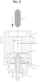
- Fig. 2 shows the loading of the preform 2 with a glass gob 1 as part of the method according to the invention.
- a glass gob 1 is introduced from above from a distributor (feeder) into a preform 2, which has a longitudinally divided mold division.
- the glass gob 1 is guided axially 2.1 during vertical free fall at a funnel opening 3 provided in the upper part of the preform 2.
- a punch tool 4 with integrated cooling tube 7, a neck mold 5 and a cover ring 6 which is guided radially and axially 2.1 in the neck mold 5 .
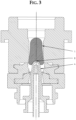
- Fig. 3 shows how the stamping tool 4 according to the present invention serves as a fall limiter for loading the glass gob 1.
- the stamping tool 4 is positioned here in the so-called loading position 8 and serves there as a fall limiter for loading the glass gob 1.
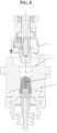
- Fig. 4 shows the beginning of a vertical closing movement of the preform bottom pressing system 9 according to the present invention.
- the preform bottom pressing system 9 closes the preform 2 at its upper end by means of a vertical movement from top to bottom.
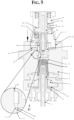
- Fig. 5 shows the further closing movement of the preform bottom pressing system 9 and the pressing process of the punch tool 4 against the parison 1.1 being formed in the preform upwards according to the present invention.
- the preform base pressing system 9 is axially aligned and guided by the preform 2 using a diameter guide 9.4 .
- the piston 9.1 is not pressurized with compressed air 18 and is pressed vertically upward against an integrated stop surface 9.3 by springs 9.2 .
- a pressing element 10, which serves to preform the base, is thus in the loading position.
- the pressing element 10 is first axially aligned on an upper hopper guide 10.1 . This occurs before the lower guide diameter 10.2 on the pressing element 10 penetrates the preform profile 11.
- the vertical closing movement of the preform base pressing system 9 is completed as soon as the stop 14 on the preform base pressing system 9 reaches the stop surface 15 on the preform 2.
- the piston 9.1 is pressed downwards by means of compressed air 18 against the springs 9.2 until it reaches the stop surface 9.6 .
- the pressing element 10 is now in the pressing position.
- the punch tool 4 is pressed upward against the parison 1.1 forming in the preform 2 against the pressing element 10, which is in the pressing position (see above).
- the movements and cooling options of the punch tool 4 and its integrated cooling tube 7 are preferably carried out in a known manner by the corresponding IS machine elements and mechanisms.
- the movement of the stamping tool 4 ends as soon as its stamping surface 4.1 rests against the cover ring surface 6.1 .
- the stamping tool 4 is pressed against the cover ring 6 until the pressing process is completed.
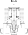
- Fig. 6a shows the integrated internal cooling of the pressing element 10 of the preform base pressing system 9 according to the invention as well as its operation according to the method according to the invention.
- the preform base pressing system 9 has integrated internal cooling of the pressing element 10.
- a compressed air source commonly used in IS glass machines is used for the so-called blowing process.
- This compressed air is supplied via a cooling medium supply line 16 serving as its inlet and is used to cool the pressing element 10.
- This compressed air which serves as the cooling medium here, is directed via the piston 9.1 through a cooling pipe 9.5 integrated in the piston 9.1 onto the inner surfaces 17.1 of the pressing element 10.
- the forced convection in the area 17.2 between the cooling medium (for example, compressed air - see above - as cooling air or fluid) and the inner surfaces 17.1 of the pressing element 10 cools the latter and thus stabilizes its solid-state temperature.
- the cooling medium is preferably separated from the working chamber 22 of the piston 9.1 by a sealing package 24 installed on the cooling medium supply line 16 .
- Fig. 6b shows the result of a flow analysis which shows the forced convection on the pressing element in the embodiment according to the present invention with integrated internal cooling of the pressing element according to Fig. 6a
- the flow pattern is shown.
- the heated cooling medium preferably the cooling air
- the cooling medium supply line 16 escapes.
- Cooling also leads to a reduction of the play (see also Fig. 7 ) 11.1 between pressing element 10 and preform profile 11 , which also counteracts the formation of an undesirably strong preform bottom seam 19 .
- Fig. 6c shows an embodiment according to the present invention in which venting slots 23 are provided on the pressing element of the preform base pressing system, ensuring venting of the medium, preferably air, that must escape due to displacement during the pressing process.
- venting slots are also provided on the guide part.
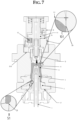
- Fig. 7 illustrates once again the effects of the present invention, particularly with regard to avoiding the formation of burrs between the press ram 4 and the guide ring within the mouth inlet, but also ensuring the quality of the glass containers to be produced with regard to undesirable burr formation on the preform bottom seam.
- Compensation for possible mass or weight fluctuations of the glass gob 1 is achieved via the stroke of the piston 9.1 , which, as already mentioned, can be achieved in various ways – preferably by measuring and evaluating the pressure applied to the piston.
- the pressure in the parison 1.1 displaces the piston 9.1 against the force of the gas pressure acting on the piston 9.1 . This force completes the pressing of the parison 1.1 .
- the mass or weight compensation counteracts the penetration of glass mass into the gap 11.1 between the pressing element 10 and the preform profile 11 , which helps to avoid the undesirable formation of a burr 19 on the preform base (see also Fig. 10a ) and thus serves to ensure the quality of the glass container to be manufactured in this area.
- the stamping tool 4 Due to the mass or weight compensation in the preform base-press system 9 , the stamping tool 4 always has the same final working position due to the limitation on the cover ring 6 , regardless of the mass or weight of the glass gob 1 or parison 1.1 and the volume of the preform profile 11. This also makes it possible to change the position of the burr between the stamping tool 4 and the cover ring 6 in the area outside the mouth opening. The resulting new position of the burr 21 - which is then no longer disruptive - outside the mouth opening in the area of the mouth is not only here, but also in Fig.
- Fig. 8 shows the demoulding after completion of the pressing process, where the punch tool 4 is moved vertically downwards out of the parison 1.1 and the preform 2 and the preform bottom pressing system 9 is moved vertically upwards and the preform 2 is opened.
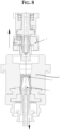
- Fig. 9 finally shows a transfer of the parison 1.1 formed according to the invention to a final forming station, wherein in the illustration shown here a corresponding pivoting movement of the parison 1.1 is indicated by the arc pointing upwards to the right.
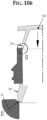
- Fig. 10a and Fig. 10b show the problem of sharp-edged forming seams on the parison.
- EP 0 327 240 A1 which has a device (cf. there for example Fig. 1 ) for a blow molding process on so-called IS ( Individual Section ) glass forming machines, so that sharp-edged forming seams can occur on the parison.
- the final working position of the press ram is determined by the resistance created between the press ram and the parison formed in the preform (i.e., the glass pressed against the preform and neck mold) and is thus dependent on the volume of the preform cavity and/or the mass or weight of the glass gob. Due to fluctuations in the mass of the glass gob, the final working position of the press ram, which is slightly conical to almost cylindrical in its guide towards the neck mold, reaches different end positions.
- parison 1.1 the glass pressed onto the preform and neck is referred to as parison 1.1 .
- the position of the gap and thus of the glass seam 20 is positioned directly at the parison entrance and in the process according to the EP 0 327 240 A1 on the conical, almost cylindrical guide part of the press ram due to the weight compensation realized via the press ram resistance, which is required to compensate for the mass fluctuations of the glass gob.
- Fig. 10c shows a modified position of the ridge in the area of the mouth entrance, which is achieved by the present invention, which uses the Fig. 10a and 10b avoids the disadvantages mentioned above by ensuring that the punch tool remains pressed against the cover ring 6 during the pressing process until its end, thus avoiding the disturbing burr 20 (see above) which forms between the press punch and the guide ring according to the prior art, since at most a non-disturbing burr 21 - if at all - forms outside the mouth entrance.
- the present invention ensures the formation of a preform base with a ridge 19 (see the left half of the illustration in Fig. 10a ) which is considerably smaller than the state of the art - if it still exists at all - and can thus be blown downwards onto the bottom of the container in a curve to position 19.1 during the subsequent final forming process (see the right half of the illustration in Fig. 10a ) and thus also ensures a high quality of the bottom of the glass container to be manufactured.
Landscapes
- Engineering & Computer Science (AREA)
- Chemical & Material Sciences (AREA)
- Manufacturing & Machinery (AREA)
- Materials Engineering (AREA)
- Organic Chemistry (AREA)
- Mechanical Engineering (AREA)
- Blow-Moulding Or Thermoforming Of Plastics Or The Like (AREA)
- Containers Having Bodies Formed In One Piece (AREA)
Claims (14)
- Système de pressage de fond de moule ébaucheur (9) pour la formation d'une entrée d'embouchure sans bavure d'un récipient en verre à fabriquer, qui comprend un piston (9.1) actionné par l'alimentation en pression de gaz, de préférence de l'air comprimé (18), et un élément de pressage (10) avec un profil d'élément de pressage (10.3), le piston (9.1) amenant, lorsqu'il est soumis à une pression de gaz d'un côté, le système de pressage de moule ébaucheur (9) en position de pressage contre une gouttes de verre (1) à former dans un moule ébaucheur (2), et préformant un fond pour le récipient en verre à produire lors du contact du profil de l'élément de pressage (10.3) avec la goutte de verre (1), caractérisé par le fait que le système de pressage de fond de moule ébaucheur (9) comprend un contrôle ou régulation de la course du piston (9.1), qui sert à compenser les fluctuations de masse de la gouttes de verre (1), le système pressage de fond de moule ébaucheur (9) ayant un dispositif de refroidissement interne pour le refroidissement au moyen d'un fluide de refroidissement
- Système de pressage de fond de moule ébaucheur (9) pour la formation d'une entrée d'embouchure sans bavure d'un récipient en verre à fabriquer selon la revendication 1, caractérisé en ce que le dispositif de refroidissement interne pour le refroidissement comporte un moyen de distribution ciblée de refroidissement sur les surfaces intérieures (17.1) de l'élément de pressage (10).
- Système de pressage de fond de moule ébaucheur (9) pour la formation d'une entrée d'embouchure sans bavure d'un récipient en verre à fabriquer selon la revendication 1 ou 2, caractérisé en ce que le moyen de distribution ciblée du fluide de refroidissement sur les surfaces intérieures (17.1) de l'élément de pressage (10) comporte une conduite d'alimentation en fluide de refroidissement (16) pour l'air de soufflage de fixe d'une machine à verre comme air comprimé pour le refroidissement dans le piston (9.1).
- Système de pressage de fond de moule ébaucheur (9) pour la formation d'une entrée d'embouchure sans bavure d'un récipient en verre à fabriquer selon la revendication 1 ou 2 ou 3, caractérisé en ce que le moyen de distribution ciblée du fluide de refroidissement sur les surfaces intérieures (17.1) de l'élément de pressage (10) comporte un tube de refroidissement (9.5) disposé dans le piston (9.1).
- Système de pressage de fond de moule ébaucheur (9) pour la formation d'une entrée d'embouchure sans bavure d'un récipient en verre à fabriquer selon la revendication 3 ou 4, caractérisé en ce que le fluide de refroidissement est séparé de la zone de travail (22) du piston (9.1) par un ensemble d'étanchéité (24) inséré au niveau de la conduite d'alimentation en fluide de refroidissement (16).
- Système de pressage de fond de moule ébaucheur (9) pour la formation d'une entrée d'embouchure sans bavure d'un récipient en verre à fabriquer selon l'une des revendications 1 à 5, caractérisé en ce que le profil de l'élément de pressage (10.3) présente une géométrie convexe ou concave courbée vers la goutte de verre (1).
- Système de pressage de fond de moule ébaucheur (9) pour la formation d'une entrée d'embouchure sans bavure d'un récipient en verre à fabriquer selon l'une des revendications 1 à 6, caractérisé en ce que l'élément de pressage (10) est fixé au piston (9.1) au moyen d'une liaison amovible.
- Système de pressage de fond de moule ébaucheur (9) pour la formation d'une entrée d'embouchure sans bavure d'un récipient en verre à fabriquer selon la revendication 7, caractérisé en ce qu'un filetage (9.8) sert de liaison détachable.
- Système de pressage de fond de moule ébaucheur (9) pour la formation d'une entrée d'embouchure sans bavure d'un récipient en verre à fabriquer selon l'une des revendications 1 à 8, caractérisé en ce que le système de pressage de fond de moule ébaucheur (9) comprend des ressorts (9.2) qui pressent l'élément de pressage (10) vers le haut contre une surface de butée (9.3) de préférence intégrée et le maintiennent ainsi dans la position de chargement tant que le piston (9.1) n'est pas soumis à une pression de gaz.
- Système de pressage de fond de moule ébaucheur (9) pour la formation d'une entrée d'embouchure sans bavure d'un récipient en verre à fabriquer selon l'une des revendications 1 à 9, caractérisé en ce que le système de pressage de fond de moule ébaucheur (9) comprend un palier lisse (12) et un guide d'entonnoir (10.1) fixé en haut dans le moule ébaucheur (2), qui guident le piston (9.1) avec l'élément de pressage (10) axialement par rapport au profil de moule ébaucheur (11) avant que l'élément de pressage (10) ne plonge dans le profil de moule ébaucheur (11).
- Procédé de fabrication d'une paraison (1.1) à l'aide d'un système de pressage de fond de moule ébaucheur (9) selon l'une des revendications 1 à 10, dans lequela) - de préférence à partir d'un dispositif d'alimentation - une goutte de verre (1) est chargée par le haut dans un moule ébaucheur (2), etb) un outil plongeur (4) est positionné dans une position de chargement (8) servant de limite de chute pour le chargement de la goutte de verre (1) à l'extrémité inférieure du moule ébaucheur (2),c) le système de pressage de fond de moule ébaucheur (9) effectue un mouvement de fermeture vertical en étant déplacé par le haut dans le moule ébaucheur (2) jusqu'à ce qu'une butée (14) du système de pressage de fond de moule ébaucheur (9) atteigne une surface de butée (15) sur le moule ébaucheur (2), le piston (9.1) n'étant initialement pas soumis à la pression du gaz, mais étant ensuite soumis à la pression du gaz peu avant ou au moment d'atteindre la surface de butée (15) et ainsi pressé vers le bas jusqu'à la surface de butée (15), l'élément de pressage (10) étant en position de pressage, et une compensation des fluctuations de masse de la goutte de verre (1) étant obtenue par une contrôle ou régulation de la course du piston,d) pendant le mouvement de fermeture vertical du système de pressage de fond de moule ébaucheur (9), l'outil plongeur (4) est en outre pressé contre la paraison (1.1) se formant dans le moule ébaucheur (2) vers le haut contre l'élément de pressage (10) en position de pressage, jusqu'à ce que l'outil plongeur (4) et sa surface plongeante (4.1) viennent en butée contre une surface de anneau de couverture (6.1), contre laquelle il est pressé jusqu'à la fin du processus de pressage, ete) après la fin du processus de pressage, un démoulage a lieu, l'outil plongeur (4) étant déplacé verticalement vers le bas, le système de pressage de fond de moule ébaucheur (9) étant entraîné verticalement vers le haut et le moule ébaucheur (2) étant ouvert, après quoi un transfert vers un poste de formage final peut avoir lieu,où le système de pressage de fond de moule ébaucheur (9) est refroidi pendant la production de la paraison (1.1) au moyen d'un dispositif de refroidissement interne du système de pressage de fond de moule ébaucheur (9) avec un milieu de refroidissement, de préférence de l'air comprimé.
- Procédé selon la revendication 11 pour la fabrication d'une paraison (1.1) à l'aide d'un système de pressage de fond de moule ébaucheur (9) selon l'une des revendications 2 à 10, caractérisé en ce que le fluide de refroidissement, de préférence de l'air de soufflage sous pression provenant d'une machine à verre, est distribué spécifiquement pour le refroidissement sur les surfaces intérieures (17.1) de l'élément de pressage (11).
- Procédé selon la revendication 12 pour la fabrication d'une paraison (1.1) à l'aide d'un système de pressage de fond de moule ébaucheur (9) selon la revendication 9 ou 10, caractérisé en ce que, pendant que le système de pressage de fond de moule ébaucheur (9) effectue un mouvement vertical de fermeture en étant descendu par le haut dans le moule ébaucheur (2) et tant que le piston (9. 1) n'est pas encore soumis à la pression du gaz, le piston (9.1) est pressé verticalement vers le haut contre une surface de butée (9.3), de préférence intégrée, avec les ressorts (9.2) de système de pressage de fond de moule ébaucheur (9), et ainsi maintenu dans la position de chargement.
- Procédé selon la revendication 13 pour la fabrication d'une paraison (1.1) à l'aide d'un système de pressage de fond de moule ébaucheur (9) selon la revendication 10, caractérisé en ce que, tandis que le système de pressage de fond de moule ébaucheur (9) effectue un mouvement de fermeture vertical en étant abaissé par le haut dans le moule ébaucheur (2), l'élément de pressage (10) est aligné axialement sur le guidage en entonnoir supérieur (10.1) et à travers le palier lisse (12) avant que le diamètre de guidage inférieur (10.2) de l'élément de pressage (10) ne plonge dans le profil de moule ébaucheur (11) pour empêcher un bord d'élément de pressage (13) de basculer avec le profil de moule ébaucheur (11).
Priority Applications (1)
| Application Number | Priority Date | Filing Date | Title |
|---|---|---|---|
| SI202230147T SI4387939T1 (sl) | 2021-08-20 | 2022-07-29 | Sistem za stiskanje predoblikovanega kalupa za oblikovanje vhoda steklene posode za proizvodnjo brez zarobkov in postopek za izdelavo steklene mase s tem sistemom |
Applications Claiming Priority (2)
| Application Number | Priority Date | Filing Date | Title |
|---|---|---|---|
| DE102021004257.3A DE102021004257A1 (de) | 2021-08-20 | 2021-08-20 | Vorformboden-Preß-System zur Ausbildung eines gratfreien Mündungseingangs eines zu fertigenden Glasbehälters sowie ein Verfahren zur Herstellung eines Kübels vermittels dessen |
| PCT/DE2022/150001 WO2023020667A1 (fr) | 2021-08-20 | 2022-07-29 | Système de pressage de base de moule ébaucheur pour former une entrée d'embouchure sans bavure d'un récipient en verre à produire, et procédé de fabrication d'une paraison au moyen dudit système |
Publications (2)
| Publication Number | Publication Date |
|---|---|
| EP4387939A1 EP4387939A1 (fr) | 2024-06-26 |
| EP4387939B1 true EP4387939B1 (fr) | 2025-04-30 |
Family
ID=83149311
Family Applications (1)
| Application Number | Title | Priority Date | Filing Date |
|---|---|---|---|
| EP22761395.7A Active EP4387939B1 (fr) | 2021-08-20 | 2022-07-29 | Système de pressage de base de moule ébaucheur pour former une entrée d'embouchure sans bavure d'un récipient en verre à produire, et procédé de fabrication d'une paraison au moyen dudit système |
Country Status (7)
| Country | Link |
|---|---|
| US (1) | US20240375988A1 (fr) |
| EP (1) | EP4387939B1 (fr) |
| CN (1) | CN117794870A (fr) |
| CA (1) | CA3228768A1 (fr) |
| DE (1) | DE102021004257A1 (fr) |
| SI (1) | SI4387939T1 (fr) |
| WO (1) | WO2023020667A1 (fr) |
Families Citing this family (2)
| Publication number | Priority date | Publication date | Assignee | Title |
|---|---|---|---|---|
| EP4733278A1 (fr) | 2024-10-23 | 2026-04-29 | Noelle + von Campe GmbH & Co. KG | Couvercle en verre de cuisson et son procédé de fabrication |
| CN120553968B (zh) * | 2025-08-01 | 2025-10-21 | 山东三金玻璃机械有限公司 | 一种四滴料行列式制瓶机 |
Family Cites Families (6)
| Publication number | Priority date | Publication date | Assignee | Title |
|---|---|---|---|---|
| US781539A (en) | 1904-02-08 | 1905-01-31 | George A Marsh | Machine for making hollow glassware. |
| US4336050A (en) | 1980-01-17 | 1982-06-22 | John D. Northrup, Jr. | Method for manufacturing glass bottles |
| DE3232288C1 (de) | 1982-08-31 | 1983-10-20 | Fa. Hermann Heye, 3063 Obernkirchen | Verfahren und Vorrichtung zum Pressen eines Glaskuelbels |
| US4623374A (en) * | 1985-04-02 | 1986-11-18 | Ball Corporation | Cooling system for parison plunger |
| US4867778A (en) | 1988-02-05 | 1989-09-19 | Emhart Industries, Inc. | Individual section glass forming machine |
| DE19935866C1 (de) | 1999-07-30 | 2000-11-23 | Heye Hermann Fa | Verfahren und Vorrichtung zum Pressen eines Külbels |
-
2021
- 2021-08-20 DE DE102021004257.3A patent/DE102021004257A1/de active Pending
-
2022
- 2022-07-29 CN CN202280056760.7A patent/CN117794870A/zh not_active Withdrawn
- 2022-07-29 CA CA3228768A patent/CA3228768A1/fr active Pending
- 2022-07-29 WO PCT/DE2022/150001 patent/WO2023020667A1/fr not_active Ceased
- 2022-07-29 SI SI202230147T patent/SI4387939T1/sl unknown
- 2022-07-29 US US18/683,799 patent/US20240375988A1/en not_active Abandoned
- 2022-07-29 EP EP22761395.7A patent/EP4387939B1/fr active Active
Also Published As
| Publication number | Publication date |
|---|---|
| WO2023020667A1 (fr) | 2023-02-23 |
| CA3228768A1 (fr) | 2023-02-23 |
| CN117794870A (zh) | 2024-03-29 |
| US20240375988A1 (en) | 2024-11-14 |
| SI4387939T1 (sl) | 2025-08-29 |
| DE102021004257A1 (de) | 2023-02-23 |
| EP4387939A1 (fr) | 2024-06-26 |
Similar Documents
| Publication | Publication Date | Title |
|---|---|---|
| EP4387939B1 (fr) | Système de pressage de base de moule ébaucheur pour former une entrée d'embouchure sans bavure d'un récipient en verre à produire, et procédé de fabrication d'une paraison au moyen dudit système | |
| EP3681692B1 (fr) | Procédé et dispositif pour la fabrication de conteneur en matière plastique | |
| EP3640005B1 (fr) | Remplissage de moule à fermeture subséquente sous pression interne | |
| DE19935866C1 (de) | Verfahren und Vorrichtung zum Pressen eines Külbels | |
| DE19851133B4 (de) | Formöffnungs-und Schließmechanik für eine IS-Maschine | |
| EP0102001B1 (fr) | Procédé et appareil pour le pressage d'une paraison | |
| EP3941711B1 (fr) | Dispositif de soupape de soufflage pour un dispositif de soufflage | |
| EP4186876B1 (fr) | Machine is pour la fabrication de récipients en verre et procédé de fonctionnement d'une telle machine is | |
| EP1565410B1 (fr) | Installation de production de bouchons en verre destines a la fermeture de bouteilles | |
| EP3580035B1 (fr) | Dispositif et procédé pour transformer des préformes en matière plastique en bouteilles en matière plastique comprenant une partie fond mobile | |
| DE19851132B4 (de) | Wende- und Halsring-Haltemechanik bei einer IS-Maschine | |
| DE19851081B4 (de) | IS-Maschine | |
| EP0263409B1 (fr) | Procédé et appareil pour déformer une paraison en verre | |
| EP1377424B1 (fr) | Procede de formage de matiere thermoplastique | |
| DE102004011647A1 (de) | Verfahren und Vorrichtung zur Regelung der Glastropfenmasse bei der Herstellung von Hohlglasbehältern | |
| DE102005046819B4 (de) | IS-Glasformungsmaschine | |
| DE19851098A1 (de) | Is-Maschine | |
| DE19851068A1 (de) | IS-Maschine | |
| DE10316600A1 (de) | Verfahren und Vorrichtung zum Antrieb eines Pressstempels einer Glasformmaschine | |
| DE19851095B4 (de) | Formöffnungs- und Schließmechanik für eine IS-Maschine sowie Formtrageanordnung | |
| EP1951631B1 (fr) | Refroidissement d'orifice dans des machines a verre pour recipient et procede pour refroidir l'orifice d'un recipient en verre lors du preformage dans une machine a verre pour recipient | |
| DE19851069B4 (de) | Formöffnungs- und Schließmechanik für eine IS-Maschine | |
| DE102012208137B4 (de) | Thermoformwerkzeug zur Herstellung von becherförmigen Gegenständen aus einer erwärmten Kunststofffolie | |
| EP2208714A2 (fr) | Dispositif de production d'article en verre creux avec une commande pneumatique | |
| DE102014011310A1 (de) | Verfahren und Vorrichtung zur Verbesserung der Sicherheit des Betriebsablaufs einer Glasformmaschine |
Legal Events
| Date | Code | Title | Description |
|---|---|---|---|
| STAA | Information on the status of an ep patent application or granted ep patent |
Free format text: STATUS: UNKNOWN |
|
| STAA | Information on the status of an ep patent application or granted ep patent |
Free format text: STATUS: THE INTERNATIONAL PUBLICATION HAS BEEN MADE |
|
| PUAI | Public reference made under article 153(3) epc to a published international application that has entered the european phase |
Free format text: ORIGINAL CODE: 0009012 |
|
| STAA | Information on the status of an ep patent application or granted ep patent |
Free format text: STATUS: REQUEST FOR EXAMINATION WAS MADE |
|
| 17P | Request for examination filed |
Effective date: 20230807 |
|
| AK | Designated contracting states |
Kind code of ref document: A1 Designated state(s): AL AT BE BG CH CY CZ DE DK EE ES FI FR GB GR HR HU IE IS IT LI LT LU LV MC MK MT NL NO PL PT RO RS SE SI SK SM TR |
|
| DAV | Request for validation of the european patent (deleted) | ||
| DAX | Request for extension of the european patent (deleted) | ||
| GRAP | Despatch of communication of intention to grant a patent |
Free format text: ORIGINAL CODE: EPIDOSNIGR1 |
|
| STAA | Information on the status of an ep patent application or granted ep patent |
Free format text: STATUS: GRANT OF PATENT IS INTENDED |
|
| INTG | Intention to grant announced |
Effective date: 20241203 |
|
| GRAS | Grant fee paid |
Free format text: ORIGINAL CODE: EPIDOSNIGR3 |
|
| GRAA | (expected) grant |
Free format text: ORIGINAL CODE: 0009210 |
|
| STAA | Information on the status of an ep patent application or granted ep patent |
Free format text: STATUS: THE PATENT HAS BEEN GRANTED |
|
| AK | Designated contracting states |
Kind code of ref document: B1 Designated state(s): AL AT BE BG CH CY CZ DE DK EE ES FI FR GB GR HR HU IE IS IT LI LT LU LV MC MK MT NL NO PL PT RO RS SE SI SK SM TR |
|
| REG | Reference to a national code |
Ref country code: CH Ref legal event code: EP Ref country code: GB Ref legal event code: FG4D Free format text: NOT ENGLISH |
|
| REG | Reference to a national code |
Ref country code: DE Ref legal event code: R096 Ref document number: 502022003804 Country of ref document: DE |
|
| REG | Reference to a national code |
Ref country code: IE Ref legal event code: FG4D Free format text: LANGUAGE OF EP DOCUMENT: GERMAN |
|
| REG | Reference to a national code |
Ref country code: NL Ref legal event code: MP Effective date: 20250430 |
|
| PG25 | Lapsed in a contracting state [announced via postgrant information from national office to epo] |
Ref country code: FI Free format text: LAPSE BECAUSE OF FAILURE TO SUBMIT A TRANSLATION OF THE DESCRIPTION OR TO PAY THE FEE WITHIN THE PRESCRIBED TIME-LIMIT Effective date: 20250430 Ref country code: PT Free format text: LAPSE BECAUSE OF FAILURE TO SUBMIT A TRANSLATION OF THE DESCRIPTION OR TO PAY THE FEE WITHIN THE PRESCRIBED TIME-LIMIT Effective date: 20250901 Ref country code: ES Free format text: LAPSE BECAUSE OF FAILURE TO SUBMIT A TRANSLATION OF THE DESCRIPTION OR TO PAY THE FEE WITHIN THE PRESCRIBED TIME-LIMIT Effective date: 20250430 |
|
| PGFP | Annual fee paid to national office [announced via postgrant information from national office to epo] |
Ref country code: DE Payment date: 20250728 Year of fee payment: 4 |
|
| REG | Reference to a national code |
Ref country code: LT Ref legal event code: MG9D |
|
| PG25 | Lapsed in a contracting state [announced via postgrant information from national office to epo] |
Ref country code: GR Free format text: LAPSE BECAUSE OF FAILURE TO SUBMIT A TRANSLATION OF THE DESCRIPTION OR TO PAY THE FEE WITHIN THE PRESCRIBED TIME-LIMIT Effective date: 20250731 Ref country code: NO Free format text: LAPSE BECAUSE OF FAILURE TO SUBMIT A TRANSLATION OF THE DESCRIPTION OR TO PAY THE FEE WITHIN THE PRESCRIBED TIME-LIMIT Effective date: 20250730 |
|
| PG25 | Lapsed in a contracting state [announced via postgrant information from national office to epo] |
Ref country code: NL Free format text: LAPSE BECAUSE OF FAILURE TO SUBMIT A TRANSLATION OF THE DESCRIPTION OR TO PAY THE FEE WITHIN THE PRESCRIBED TIME-LIMIT Effective date: 20250430 Ref country code: PL Free format text: LAPSE BECAUSE OF FAILURE TO SUBMIT A TRANSLATION OF THE DESCRIPTION OR TO PAY THE FEE WITHIN THE PRESCRIBED TIME-LIMIT Effective date: 20250430 |
|
| PG25 | Lapsed in a contracting state [announced via postgrant information from national office to epo] |
Ref country code: BG Free format text: LAPSE BECAUSE OF FAILURE TO SUBMIT A TRANSLATION OF THE DESCRIPTION OR TO PAY THE FEE WITHIN THE PRESCRIBED TIME-LIMIT Effective date: 20250430 |
|
| PG25 | Lapsed in a contracting state [announced via postgrant information from national office to epo] |
Ref country code: HR Free format text: LAPSE BECAUSE OF FAILURE TO SUBMIT A TRANSLATION OF THE DESCRIPTION OR TO PAY THE FEE WITHIN THE PRESCRIBED TIME-LIMIT Effective date: 20250430 |
|
| PGFP | Annual fee paid to national office [announced via postgrant information from national office to epo] |
Ref country code: AT Payment date: 20251020 Year of fee payment: 4 Ref country code: FR Payment date: 20250723 Year of fee payment: 4 |
|
| PG25 | Lapsed in a contracting state [announced via postgrant information from national office to epo] |
Ref country code: RS Free format text: LAPSE BECAUSE OF FAILURE TO SUBMIT A TRANSLATION OF THE DESCRIPTION OR TO PAY THE FEE WITHIN THE PRESCRIBED TIME-LIMIT Effective date: 20250731 |
|
| PG25 | Lapsed in a contracting state [announced via postgrant information from national office to epo] |
Ref country code: IS Free format text: LAPSE BECAUSE OF FAILURE TO SUBMIT A TRANSLATION OF THE DESCRIPTION OR TO PAY THE FEE WITHIN THE PRESCRIBED TIME-LIMIT Effective date: 20250830 |
|
| PG25 | Lapsed in a contracting state [announced via postgrant information from national office to epo] |
Ref country code: LV Free format text: LAPSE BECAUSE OF FAILURE TO SUBMIT A TRANSLATION OF THE DESCRIPTION OR TO PAY THE FEE WITHIN THE PRESCRIBED TIME-LIMIT Effective date: 20250430 |
|
| PGFP | Annual fee paid to national office [announced via postgrant information from national office to epo] |
Ref country code: SI Payment date: 20250718 Year of fee payment: 4 |
|
| PG25 | Lapsed in a contracting state [announced via postgrant information from national office to epo] |
Ref country code: DK Free format text: LAPSE BECAUSE OF FAILURE TO SUBMIT A TRANSLATION OF THE DESCRIPTION OR TO PAY THE FEE WITHIN THE PRESCRIBED TIME-LIMIT Effective date: 20250430 Ref country code: SM Free format text: LAPSE BECAUSE OF FAILURE TO SUBMIT A TRANSLATION OF THE DESCRIPTION OR TO PAY THE FEE WITHIN THE PRESCRIBED TIME-LIMIT Effective date: 20250430 |
|
| PG25 | Lapsed in a contracting state [announced via postgrant information from national office to epo] |
Ref country code: CZ Free format text: LAPSE BECAUSE OF FAILURE TO SUBMIT A TRANSLATION OF THE DESCRIPTION OR TO PAY THE FEE WITHIN THE PRESCRIBED TIME-LIMIT Effective date: 20250430 |
|
| PG25 | Lapsed in a contracting state [announced via postgrant information from national office to epo] |
Ref country code: EE Free format text: LAPSE BECAUSE OF FAILURE TO SUBMIT A TRANSLATION OF THE DESCRIPTION OR TO PAY THE FEE WITHIN THE PRESCRIBED TIME-LIMIT Effective date: 20250430 |
|
| PG25 | Lapsed in a contracting state [announced via postgrant information from national office to epo] |
Ref country code: SK Free format text: LAPSE BECAUSE OF FAILURE TO SUBMIT A TRANSLATION OF THE DESCRIPTION OR TO PAY THE FEE WITHIN THE PRESCRIBED TIME-LIMIT Effective date: 20250430 |
|
| PG25 | Lapsed in a contracting state [announced via postgrant information from national office to epo] |
Ref country code: IT Free format text: LAPSE BECAUSE OF FAILURE TO SUBMIT A TRANSLATION OF THE DESCRIPTION OR TO PAY THE FEE WITHIN THE PRESCRIBED TIME-LIMIT Effective date: 20250430 |
|
| REG | Reference to a national code |
Ref country code: DE Ref legal event code: R097 Ref document number: 502022003804 Country of ref document: DE |
|
| REG | Reference to a national code |
Ref country code: CH Ref legal event code: H13 Free format text: ST27 STATUS EVENT CODE: U-0-0-H10-H13 (AS PROVIDED BY THE NATIONAL OFFICE) Effective date: 20260224 |
|
| PG25 | Lapsed in a contracting state [announced via postgrant information from national office to epo] |
Ref country code: RO Free format text: LAPSE BECAUSE OF FAILURE TO SUBMIT A TRANSLATION OF THE DESCRIPTION OR TO PAY THE FEE WITHIN THE PRESCRIBED TIME-LIMIT Effective date: 20250430 |
|
| PLBE | No opposition filed within time limit |
Free format text: ORIGINAL CODE: 0009261 |
|
| STAA | Information on the status of an ep patent application or granted ep patent |
Free format text: STATUS: NO OPPOSITION FILED WITHIN TIME LIMIT |
|
| REG | Reference to a national code |
Ref country code: CH Ref legal event code: L10 Free format text: ST27 STATUS EVENT CODE: U-0-0-L10-L00 (AS PROVIDED BY THE NATIONAL OFFICE) Effective date: 20260311 |
|
| PG25 | Lapsed in a contracting state [announced via postgrant information from national office to epo] |
Ref country code: LU Free format text: LAPSE BECAUSE OF NON-PAYMENT OF DUE FEES Effective date: 20250729 |
|
| REG | Reference to a national code |
Ref country code: BE Ref legal event code: MM Effective date: 20250731 |
|
| 26N | No opposition filed |
Effective date: 20260202 |
|
| PG25 | Lapsed in a contracting state [announced via postgrant information from national office to epo] |
Ref country code: BE Free format text: LAPSE BECAUSE OF NON-PAYMENT OF DUE FEES Effective date: 20250731 |
|
| PG25 | Lapsed in a contracting state [announced via postgrant information from national office to epo] |
Ref country code: CH Free format text: LAPSE BECAUSE OF NON-PAYMENT OF DUE FEES Effective date: 20250731 |