EP4387939B1 - Blank mould base pressing system for forming a burr-free mouth entry of a glass container to be produced, and method for producing a parison by means said system - Google Patents
Blank mould base pressing system for forming a burr-free mouth entry of a glass container to be produced, and method for producing a parison by means said system Download PDFInfo
- Publication number
- EP4387939B1 EP4387939B1 EP22761395.7A EP22761395A EP4387939B1 EP 4387939 B1 EP4387939 B1 EP 4387939B1 EP 22761395 A EP22761395 A EP 22761395A EP 4387939 B1 EP4387939 B1 EP 4387939B1
- Authority
- EP
- European Patent Office
- Prior art keywords
- blank mould
- pressing
- pressing system
- piston
- glass
- Prior art date
- Legal status (The legal status is an assumption and is not a legal conclusion. Google has not performed a legal analysis and makes no representation as to the accuracy of the status listed.)
- Active
Links
Images






Classifications
-
- C—CHEMISTRY; METALLURGY
- C03—GLASS; MINERAL OR SLAG WOOL
- C03B—MANUFACTURE, SHAPING, OR SUPPLEMENTARY PROCESSES
- C03B9/00—Blowing glass; Production of hollow glass articles
- C03B9/30—Details of blowing glass; Use of materials for the moulds
- C03B9/38—Means for cooling, heating, or insulating glass-blowing machines or for cooling the glass moulded by the machine
- C03B9/3825—Details thereof relating to plungers
-
- C—CHEMISTRY; METALLURGY
- C03—GLASS; MINERAL OR SLAG WOOL
- C03B—MANUFACTURE, SHAPING, OR SUPPLEMENTARY PROCESSES
- C03B11/00—Pressing molten glass or performed glass reheated to equivalent low viscosity without blowing
- C03B11/06—Construction of plunger or mould
- C03B11/10—Construction of plunger or mould for making hollow or semi-hollow articles
-
- C—CHEMISTRY; METALLURGY
- C03—GLASS; MINERAL OR SLAG WOOL
- C03B—MANUFACTURE, SHAPING, OR SUPPLEMENTARY PROCESSES
- C03B11/00—Pressing molten glass or performed glass reheated to equivalent low viscosity without blowing
- C03B11/05—Pressing molten glass or performed glass reheated to equivalent low viscosity without blowing in machines with reciprocating moulds
-
- C—CHEMISTRY; METALLURGY
- C03—GLASS; MINERAL OR SLAG WOOL
- C03B—MANUFACTURE, SHAPING, OR SUPPLEMENTARY PROCESSES
- C03B11/00—Pressing molten glass or performed glass reheated to equivalent low viscosity without blowing
- C03B11/12—Cooling, heating, or insulating the plunger, the mould, or the glass-pressing machine; cooling or heating of the glass in the mould
- C03B11/125—Cooling
- C03B11/127—Cooling of hollow or semi-hollow articles or their moulds
-
- C—CHEMISTRY; METALLURGY
- C03—GLASS; MINERAL OR SLAG WOOL
- C03B—MANUFACTURE, SHAPING, OR SUPPLEMENTARY PROCESSES
- C03B9/00—Blowing glass; Production of hollow glass articles
- C03B9/13—Blowing glass; Production of hollow glass articles in gob feeder machines
- C03B9/193—Blowing glass; Production of hollow glass articles in gob feeder machines in "press-and-blow" machines
- C03B9/1932—Details of such machines, e.g. plungers or plunger mechanisms for the press-and-blow machine, cooling of plungers
-
- C—CHEMISTRY; METALLURGY
- C03—GLASS; MINERAL OR SLAG WOOL
- C03B—MANUFACTURE, SHAPING, OR SUPPLEMENTARY PROCESSES
- C03B9/00—Blowing glass; Production of hollow glass articles
- C03B9/30—Details of blowing glass; Use of materials for the moulds
- C03B9/38—Means for cooling, heating, or insulating glass-blowing machines or for cooling the glass moulded by the machine
- C03B9/3866—Details thereof relating to bottom moulds, e.g. baffles
-
- C—CHEMISTRY; METALLURGY
- C03—GLASS; MINERAL OR SLAG WOOL
- C03B—MANUFACTURE, SHAPING, OR SUPPLEMENTARY PROCESSES
- C03B9/00—Blowing glass; Production of hollow glass articles
- C03B9/30—Details of blowing glass; Use of materials for the moulds
- C03B9/40—Gearing or controlling mechanisms specially adapted for glass-blowing machines
- C03B9/41—Electric or electronic systems
-
- C—CHEMISTRY; METALLURGY
- C03—GLASS; MINERAL OR SLAG WOOL
- C03B—MANUFACTURE, SHAPING, OR SUPPLEMENTARY PROCESSES
- C03B2215/00—Press-moulding glass
- C03B2215/50—Structural details of the press-mould assembly
-
- C—CHEMISTRY; METALLURGY
- C03—GLASS; MINERAL OR SLAG WOOL
- C03B—MANUFACTURE, SHAPING, OR SUPPLEMENTARY PROCESSES
- C03B2215/00—Press-moulding glass
- C03B2215/71—Injecting molten glass into the mould cavity
Definitions
- the present invention relates to a preform bottom pressing system for forming a burr-free mouth inlet of a glass container to be manufactured and to a method for producing a parison by means of the same.
- burrs In preform base pressing systems, particularly in the narrow neck pressing process for the cylindrical design of the inner mouth, burrs often form at the mouth entrance during state-of-the-art production.
- the EP 0 327 240 A1 a device (cf. there for example Fig. 1 ) for a blow molding process on so-called IS ( Individual Section ) glass forming machines.
- the final working position of the press ram is determined by the deformation resistance of the molten glass in the preform when the preform cavity is completely filled with glass. It therefore depends on the mass of the glass gob and/or the volume of the preform cavity. Due to fluctuations in the weight of the glass gob, the final working position reaches different end positions.
- the design of the press ram is slightly conical to almost cylindrical where it guides the mouth shape. Towards the end of the pressing process, when the press ram has almost reached its final working position, it is radially guided and centered by a non-split guide ring. Due to the guide play or gap between the guide ring and the press ram and the slight conicity of the press ram in this area, glass mass can enter the gap in certain operating situations, with the gap size depending on the respective final working position of the press ram. This can unfavorably lead to sharp-edged forming seams, a so-called burr formation, which impairs the sealing effect or assembly conditions between the glass container closure and the glass container. within the muzzle entrance can damage sealing and thus pre-tensioned closures or inserts and cause large vertical indentation forces.
- the neck mold consists of a longitudinally split neck tool and a non-longitudinally split guide ring held in a radial groove of the neck tool, which is intended to guide the press ram axially.
- the glass contact profile of the outer sealing edge of the neck is integrated into the press ram and therefore contains no mold division between the press ram and the guide ring.
- the final working position of the press ram is defined by the fact that an upper annular surface of the press ram comes into contact with an annular counter-surface of the neck tool.
- the DE 32 32 288 C1 attempts to utilize a fixed additional volume at the beginning of the molding process to compensate for mass fluctuations and also uses compressed air control to reduce the thermal load on the piston.
- the piston stroke itself like the aforementioned additional volume, is fixed and influenced only by the operating cycle.
- the DE 20 10 443 A1 attempts to achieve mass balance through a purely mechanical device in the form of a spring-loaded preform base on the side opposite the press ram.
- the press ram itself operates within a fixed, predetermined clearance, namely always up to a certain height.
- the spring-loaded preform base is only capable of achieving mass balance to a very limited extent, namely a fixed maximum set by a pin.
- the EP 1 129 039 B1 attempts to counteract this problem by measuring the lowest piston position of the pressing element by means of a potentiometer in order to then use this to adjust the mass of the glass gob via the stroke of the plunger on the feeder (cf. EP 1 129 039 B1 , paragraph [0038]).
- the object of the present invention is to avoid the formation of burrs between the press die and the guide ring within the mouth inlet, but at the same time to ensure the quality of the glass containers to be produced by avoiding excessive burr formation on the preform bottom seam and to avoid tilting or jamming of the press element and preform during production.
- the preform base pressing system according to the invention for forming a burr-free mouth opening for a glass container to be manufactured has - similar to the State of the art according to EP 1 129 039 B1 - a piston operated by applying gas pressure, preferably compressed air, and a pressing element with a pressing element profile, wherein the piston, when subjected to gas pressure on one side, brings the preform base pressing system into the pressing position relative to a glass gob to be formed in a preform and, in the process, preforms a base for the glass container to be produced in contact between the pressing element profile and the glass gob.
- the present invention differs from the prior art according to EP 1 129 039 B1 by providing a control or regulation of the piston stroke, which serves to compensate for fluctuations in the mass of the glass gob by adapting this stroke to the respective glass gob mass.
- Such an adjustment of the piston stroke can preferably be carried out using a gas pressure sensor, which measures the gas pressure currently applied to the piston. If a more massive gob falls into the preform, the volume of the glass mass there is also larger and the piston reaches the gob sooner, whereupon the gas pressure of the piston increases rapidly as a result of the essentially incompressible liquid glass mass immediately after the pressing element comes into contact with the glass mass. If this pressure is now measured, preferably using a gas pressure sensor, the required stroke until the glass gob is reached is ultimately determined and a further piston stroke can then be stopped or slowed down in time before the glass mass penetrates too deeply into the gap between the parison and the preform wall in the area of the parison base. In this way, mass fluctuations of the glass gob can be compensated for via the piston stroke, for example, for the parison currently being produced.
- a non-contact sensor such as an optical sensor (e.g. a laser sensor) that uses triangulation measurement or
- systems can also be provided that determine the actual mass of the glass gob falling into the preform, for example by measuring its spatial extent (and specific gravity) using an image acquisition system, and then use this to determine the required piston stroke.
- this provides a variety of technical options that allow for compensating for mass fluctuations of the glass gob via the piston stroke.
- the preform base pressing system for forming a burr-free mouth inlet for a glass container to be manufactured according to the present invention also has an internal cooling device for cooling by means of a cooling medium, whereby the prior art according to the EP 1 129 039 B1
- the potential disadvantage of heating and volume expansion of the pressing element due to prolonged contact with the warm glass mass can also be avoided, thus preventing tilting or jamming of the pressing element and preform, and thus significant process disruptions.
- the method for producing a parison is also designed such that during production of the parison, it is cooled with a cooling medium, preferably compressed air, by means of the internal cooling device of the preform base pressing system according to the invention.
- the cooling medium is distributed specifically onto the inner surfaces of the pressing element by means of suitable means for this purpose, such as a cooling medium supply line in the piston for solid blowing air (compressed air) of a glass machine and/or a cooling tube arranged in the piston.
- suitable means for this purpose such as a cooling medium supply line in the piston for solid blowing air (compressed air) of a glass machine and/or a cooling tube arranged in the piston.
- the cooling medium is separated from the working chamber of the piston by a seal - such as a sealing package - installed on the cooling medium supply line.
- demoulding takes place after completion of the pressing process, with the stamping tool being moved vertically downwards and the The preform bottom press system is extended vertically upwards and the preform is opened, after which it can be transferred to a final forming station for forming the glass container from the preformed parison.
- the pressing element profile of the pressing element of the preform base pressing system according to the invention preferably has a convex geometry curved towards the glass gob, which advantageously reduces the pressing pressure applied by the pressing element in the parison.
- the pressing element can also preferably be attached to the piston by means of a detachable connection, which allows for easy replacement.
- a threaded connection can preferably serve as the detachable connection.
- other detachable connections such as bayonet locks, are also possible.
- this system preferably integrated into the preform base pressing system according to the invention—comprises springs that press the pressing element upwards against a—preferably integrated—stop surface and thus hold it in the loading position as long as the piston is not subjected to gas pressure.
- springs support the aforementioned mass equalization of the glass gob via the piston stroke, as they can dampen the pressure of the pressing element on the glass mass and ensure that the pressing element does not come into contact with the glass twice, which would negatively affect the quality of the parison formation.
- somewhat more reaction time is available for a control or regulation of the piston stroke used to adapt to the mass of the glass gob, which facilitates the control and/or regulation of the process.
- said system comprises a sliding bearing and/or a funnel guide mounted at the top of the preform, which guide the piston with pressing element axially to the preform profile before the pressing element dips into the preform profile, which can effectively counteract any jamming of the pressing element edge with the preform profile.
- Fig. 1 provides an overview of the method according to the invention for producing a parison by means of a preform base pressing system 9 according to the present invention in a schematic representation of individual production steps arranged step by step in rows from top to bottom and from left to right.
- an internal cooling device (see in particular Fig. 6a , 6b , 6c ) of the preform base pressing system 9 is cooled with a cooling medium, preferably compressed air.
- a cooling medium preferably compressed air.
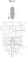
- Fig. 2 shows the loading of the preform 2 with a glass gob 1 as part of the method according to the invention.
- a glass gob 1 is introduced from above from a distributor (feeder) into a preform 2, which has a longitudinally divided mold division.
- the glass gob 1 is guided axially 2.1 during vertical free fall at a funnel opening 3 provided in the upper part of the preform 2.
- a punch tool 4 with integrated cooling tube 7, a neck mold 5 and a cover ring 6 which is guided radially and axially 2.1 in the neck mold 5 .
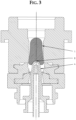
- Fig. 3 shows how the stamping tool 4 according to the present invention serves as a fall limiter for loading the glass gob 1.
- the stamping tool 4 is positioned here in the so-called loading position 8 and serves there as a fall limiter for loading the glass gob 1.
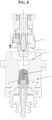
- Fig. 4 shows the beginning of a vertical closing movement of the preform bottom pressing system 9 according to the present invention.
- the preform bottom pressing system 9 closes the preform 2 at its upper end by means of a vertical movement from top to bottom.
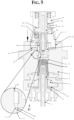
- Fig. 5 shows the further closing movement of the preform bottom pressing system 9 and the pressing process of the punch tool 4 against the parison 1.1 being formed in the preform upwards according to the present invention.
- the preform base pressing system 9 is axially aligned and guided by the preform 2 using a diameter guide 9.4 .
- the piston 9.1 is not pressurized with compressed air 18 and is pressed vertically upward against an integrated stop surface 9.3 by springs 9.2 .
- a pressing element 10, which serves to preform the base, is thus in the loading position.
- the pressing element 10 is first axially aligned on an upper hopper guide 10.1 . This occurs before the lower guide diameter 10.2 on the pressing element 10 penetrates the preform profile 11.
- the vertical closing movement of the preform base pressing system 9 is completed as soon as the stop 14 on the preform base pressing system 9 reaches the stop surface 15 on the preform 2.
- the piston 9.1 is pressed downwards by means of compressed air 18 against the springs 9.2 until it reaches the stop surface 9.6 .
- the pressing element 10 is now in the pressing position.
- the punch tool 4 is pressed upward against the parison 1.1 forming in the preform 2 against the pressing element 10, which is in the pressing position (see above).
- the movements and cooling options of the punch tool 4 and its integrated cooling tube 7 are preferably carried out in a known manner by the corresponding IS machine elements and mechanisms.
- the movement of the stamping tool 4 ends as soon as its stamping surface 4.1 rests against the cover ring surface 6.1 .
- the stamping tool 4 is pressed against the cover ring 6 until the pressing process is completed.
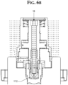
- Fig. 6a shows the integrated internal cooling of the pressing element 10 of the preform base pressing system 9 according to the invention as well as its operation according to the method according to the invention.
- the preform base pressing system 9 has integrated internal cooling of the pressing element 10.
- a compressed air source commonly used in IS glass machines is used for the so-called blowing process.
- This compressed air is supplied via a cooling medium supply line 16 serving as its inlet and is used to cool the pressing element 10.
- This compressed air which serves as the cooling medium here, is directed via the piston 9.1 through a cooling pipe 9.5 integrated in the piston 9.1 onto the inner surfaces 17.1 of the pressing element 10.
- the forced convection in the area 17.2 between the cooling medium (for example, compressed air - see above - as cooling air or fluid) and the inner surfaces 17.1 of the pressing element 10 cools the latter and thus stabilizes its solid-state temperature.
- the cooling medium is preferably separated from the working chamber 22 of the piston 9.1 by a sealing package 24 installed on the cooling medium supply line 16 .
- Fig. 6b shows the result of a flow analysis which shows the forced convection on the pressing element in the embodiment according to the present invention with integrated internal cooling of the pressing element according to Fig. 6a
- the flow pattern is shown.
- the heated cooling medium preferably the cooling air
- the cooling medium supply line 16 escapes.
- Cooling also leads to a reduction of the play (see also Fig. 7 ) 11.1 between pressing element 10 and preform profile 11 , which also counteracts the formation of an undesirably strong preform bottom seam 19 .
- Fig. 6c shows an embodiment according to the present invention in which venting slots 23 are provided on the pressing element of the preform base pressing system, ensuring venting of the medium, preferably air, that must escape due to displacement during the pressing process.
- venting slots are also provided on the guide part.
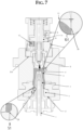
- Fig. 7 illustrates once again the effects of the present invention, particularly with regard to avoiding the formation of burrs between the press ram 4 and the guide ring within the mouth inlet, but also ensuring the quality of the glass containers to be produced with regard to undesirable burr formation on the preform bottom seam.
- Compensation for possible mass or weight fluctuations of the glass gob 1 is achieved via the stroke of the piston 9.1 , which, as already mentioned, can be achieved in various ways – preferably by measuring and evaluating the pressure applied to the piston.
- the pressure in the parison 1.1 displaces the piston 9.1 against the force of the gas pressure acting on the piston 9.1 . This force completes the pressing of the parison 1.1 .
- the mass or weight compensation counteracts the penetration of glass mass into the gap 11.1 between the pressing element 10 and the preform profile 11 , which helps to avoid the undesirable formation of a burr 19 on the preform base (see also Fig. 10a ) and thus serves to ensure the quality of the glass container to be manufactured in this area.
- the stamping tool 4 Due to the mass or weight compensation in the preform base-press system 9 , the stamping tool 4 always has the same final working position due to the limitation on the cover ring 6 , regardless of the mass or weight of the glass gob 1 or parison 1.1 and the volume of the preform profile 11. This also makes it possible to change the position of the burr between the stamping tool 4 and the cover ring 6 in the area outside the mouth opening. The resulting new position of the burr 21 - which is then no longer disruptive - outside the mouth opening in the area of the mouth is not only here, but also in Fig.
- Fig. 8 shows the demoulding after completion of the pressing process, where the punch tool 4 is moved vertically downwards out of the parison 1.1 and the preform 2 and the preform bottom pressing system 9 is moved vertically upwards and the preform 2 is opened.
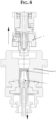
- Fig. 9 finally shows a transfer of the parison 1.1 formed according to the invention to a final forming station, wherein in the illustration shown here a corresponding pivoting movement of the parison 1.1 is indicated by the arc pointing upwards to the right.
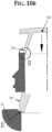
- Fig. 10a and Fig. 10b show the problem of sharp-edged forming seams on the parison.
- EP 0 327 240 A1 which has a device (cf. there for example Fig. 1 ) for a blow molding process on so-called IS ( Individual Section ) glass forming machines, so that sharp-edged forming seams can occur on the parison.
- the final working position of the press ram is determined by the resistance created between the press ram and the parison formed in the preform (i.e., the glass pressed against the preform and neck mold) and is thus dependent on the volume of the preform cavity and/or the mass or weight of the glass gob. Due to fluctuations in the mass of the glass gob, the final working position of the press ram, which is slightly conical to almost cylindrical in its guide towards the neck mold, reaches different end positions.
- parison 1.1 the glass pressed onto the preform and neck is referred to as parison 1.1 .
- the position of the gap and thus of the glass seam 20 is positioned directly at the parison entrance and in the process according to the EP 0 327 240 A1 on the conical, almost cylindrical guide part of the press ram due to the weight compensation realized via the press ram resistance, which is required to compensate for the mass fluctuations of the glass gob.
- Fig. 10c shows a modified position of the ridge in the area of the mouth entrance, which is achieved by the present invention, which uses the Fig. 10a and 10b avoids the disadvantages mentioned above by ensuring that the punch tool remains pressed against the cover ring 6 during the pressing process until its end, thus avoiding the disturbing burr 20 (see above) which forms between the press punch and the guide ring according to the prior art, since at most a non-disturbing burr 21 - if at all - forms outside the mouth entrance.
- the present invention ensures the formation of a preform base with a ridge 19 (see the left half of the illustration in Fig. 10a ) which is considerably smaller than the state of the art - if it still exists at all - and can thus be blown downwards onto the bottom of the container in a curve to position 19.1 during the subsequent final forming process (see the right half of the illustration in Fig. 10a ) and thus also ensures a high quality of the bottom of the glass container to be manufactured.
Landscapes
- Engineering & Computer Science (AREA)
- Chemical & Material Sciences (AREA)
- Manufacturing & Machinery (AREA)
- Materials Engineering (AREA)
- Organic Chemistry (AREA)
- Mechanical Engineering (AREA)
- Blow-Moulding Or Thermoforming Of Plastics Or The Like (AREA)
- Containers Having Bodies Formed In One Piece (AREA)
Description
Die vorliegende Erfindung betrifft ein Vorformboden-Press-System zur Ausbildung eines gratfreien Mündungseingangs eines zu fertigenden Glasbehälters sowie ein Verfahren zur Herstellung eines Külbels vermittels dessen.The present invention relates to a preform bottom pressing system for forming a burr-free mouth inlet of a glass container to be manufactured and to a method for producing a parison by means of the same.
Bei Vorformboden-Press-Systemen, insbesondere im Enghalspreßverfahren zur zylindrischen Ausführung des Mündungsinnenverlaufes entsteht bei der Fertigung nach dem Stand der Technik häufig eine Gratbildung am Mündungseingang.In preform base pressing systems, particularly in the narrow neck pressing process for the cylindrical design of the inner mouth, burrs often form at the mouth entrance during state-of-the-art production.
So zeigt etwa die
Der Preßstempel ist in seinem Design an seiner Führung zu der Mündungsform leicht konisch bis fast zylindrisch gestaltet. Gegen Ende des Pressvorganges, dann wenn der Preßstempel seine Arbeitsendstellung nahezu erreicht hat, wird dieser durch einen nicht längsgeteilten Führungsring radial geführt und zentriert. Wegen des Führungsspiels bzw. Spalts zwischen Führungsring und Pressstempel und der leichten Konizität des Pressstempels in diesem Bereich kann in bestimmten Betriebssituationen Glasmasse in den Spalt gelangen, wobei die Spaltgröße abhängig von der jeweiligen Arbeitsendstellung des Pressstempels ist. Dies kann ungünstigerweise zu scharfkantigen Formnähten, einer sogenannten Gratbildung führen, die die Dichtwirkung bzw. Montagebedingungen zwischen Glasbehälterverschluss und Glasbehälter verschlechtern sowie innerhalb des Mündungseinganges dichtende und somit vorgespannte Verschlüsse oder Einsätze beschädigen und große vertikale Eindrückkräfte bewirken können.The design of the press ram is slightly conical to almost cylindrical where it guides the mouth shape. Towards the end of the pressing process, when the press ram has almost reached its final working position, it is radially guided and centered by a non-split guide ring. Due to the guide play or gap between the guide ring and the press ram and the slight conicity of the press ram in this area, glass mass can enter the gap in certain operating situations, with the gap size depending on the respective final working position of the press ram. This can unfavorably lead to sharp-edged forming seams, a so-called burr formation, which impairs the sealing effect or assembly conditions between the glass container closure and the glass container. within the muzzle entrance can damage sealing and thus pre-tensioned closures or inserts and cause large vertical indentation forces.
Bei einer weiteren aus dem Stand der Technik bekannten Vorrichtung nach der
Auf diese Weise wird zwar der Nachteil der
Die
Zur Minderung der thermischen Belastung - in diesem Falle des Kolbens - setzt die
Die
Die
Eine solche Vorgehensweise kann aber naturgemäß allenfalls den nächsten Glasposten von seiner Masse her ausgleichen, nicht jedoch den gerade aktuell zur Fertigung verwendeten, der den hierdurch womöglich hervorgerufenen Qualitätsmangel am Boden des Külbels bzw. späteren Glasbehälters bereits erlitten hat.Such an approach can, of course, at best compensate for the mass of the next batch of glass, but not for the batch currently being used for production, which has already suffered the resulting quality defect at the bottom of the gob or later glass container.
Auch ist es ein Nachteil der
Vor dem Hintergrund des vorerwähnten Standes der Technik ist es daher ausgehend von der
Diese Aufgabe wird erfindungsgemäß durch ein Vorformboden-Preß-System nach Anspruch 1 und ein Verfahren zur Herstellung eines Külbels vermittels eines solchen erfindungsgemäßen-Vorformboden-Preß-Systems nach Anspruch 11 gelöst. Zweckmäßige Ausführungsformen ergeben sich dabei aus den Ansprüchen 2 bis 9 und 11 bis 14.This object is achieved according to the invention by a preform base pressing system according to
Das erfindungsgemäße Vorformboden-Preß-System zur Ausbildung eines gratfreien Mündungseingangs für einen bzw. eines zu fertigenden Glasbehälters weist dabei - ähnlich wie der Stand der Technik nach
Eine solche Anpassung des Hubs des Kolbens kann bevorzugterweise etwa vermittels eines Gasdrucksensors erfolgen, der den Gasdruck, mit dem der Kolben gerade beaufschlagt ist, mißt. Fällt nämlich ein massereicherer Tropfen in die Vorform, so ist auch das Volumen der Glasmasse dort größer und der Kolben erreicht eher den Tropfen, worauf der Gasdruck des Kolbens infolge der im wesentlichen inkompressiblem flüssigen Glasmasse alsbald nach Inkontakttreten des Preßelements mit der Glasmasse rasch ansteigt. Mißt man nun etwa diesen Druck, vorzugsweise mittels eines Gasdrucksensors, so stellt man damit letztlich auch den erforderlichen Hub bis zum Erreichen des Glastropfens fest und kann dann einen weiteren Kolbenhub rechtzeitig stoppen oder verlangsamen, bevor es zu einem zu starken Eindringen der Glasmasse in den Spalt zwischen Külbel und Vorformwandung im Bereich des Külbelbodens kommt. So kann etwa ein Ausgleich von Masseschwankungen des Glastropfens über den Kolbenhub erfolgen und zwar für das aktuell gefertigte Külbel.Such an adjustment of the piston stroke can preferably be carried out using a gas pressure sensor, which measures the gas pressure currently applied to the piston. If a more massive gob falls into the preform, the volume of the glass mass there is also larger and the piston reaches the gob sooner, whereupon the gas pressure of the piston increases rapidly as a result of the essentially incompressible liquid glass mass immediately after the pressing element comes into contact with the glass mass. If this pressure is now measured, preferably using a gas pressure sensor, the required stroke until the glass gob is reached is ultimately determined and a further piston stroke can then be stopped or slowed down in time before the glass mass penetrates too deeply into the gap between the parison and the preform wall in the area of the parison base. In this way, mass fluctuations of the glass gob can be compensated for via the piston stroke, for example, for the parison currently being produced.
Dies stellt aber beileibe nicht die einzige Möglichkeit dar, den Ausgleich von Masseschwankungen des Glastropfens über den Kolbenhub zu realisieren. So ist es etwa auch möglich, zu messen bis zu welcher Höhe der in die Vorform eingebrachte Glastropfen die Vorform füllt, was etwa mittels eines berührungsfrei arbeitenden Sensors, etwa einem optischen Sensor (z.B. einem Lasersensor) der sich etwa einer Triangulationsmessung oder einer Laufzeitmessung bedient oder auch einem 3D-Stereoaufnahme-Sensor geschehen kann. Auf diese Weise ist infolge der Messung der Füllhöhe der Vorform mit Glasmasse dann auch der Weg bestimmt, den der Kolben des Vorformboden-Preß-Systems zurücklegen muß, um das Preßelement zur Vorformung des Bodens in Kontakt mit der Glasmasse zu bringen. So kann dann am Kolben ein Wegmeßsystem vorgesehen sein, das es erlaubt das Preßelement entsprechend der tatsächlichen Füllhöhe der Vorform mit Glasmasse und damit angepaßt an die aktuelle Glasmasse über den Kolbenhub zu verfahren und so Masseschwankungen des Glastropfens über den Kolbenhub auszugleichen.However, this is by no means the only way to compensate for fluctuations in the mass of the glass gob via the piston stroke. It is also possible, for example, to measure the height to which the glass gob introduced into the preform fills the preform. This can be done using a non-contact sensor, such as an optical sensor (e.g. a laser sensor) that uses triangulation measurement or a time-of-flight measurement, or even a 3D stereo recording sensor. In this way, the measurement of the fill level of the preform with glass mass then determines the distance that the piston of the preform base pressing system must travel in order to bring the pressing element into contact with the glass mass for preforming the base. A distance measuring system can then be provided on the piston, which allows the pressing element to be adjusted according to the actual fill level. the preform with glass mass and thus adapted to the current glass mass via the piston stroke and thus to compensate for mass fluctuations of the glass gob via the piston stroke.
Ferner können aber auch Systeme vorgesehen sein, die die tatsächliche Masse des in die Vorform fallenden Glastropfens, etwa über eine Erfassung seiner räumlichen Ausdehnung (und des spezifischen Gewichts) etwa mittels eines Bilderfassungssystems bestimmen und hieraus den notwendigen Kolbenhubweg ermitteln. Letztlich sind somit eine Vielzahl von technischen Möglichkeiten gegeben, die es erlauben, einen Ausgleich von Masseschwankungen des Glastropfens über den Kolbenhub vorzunehmen.Furthermore, systems can also be provided that determine the actual mass of the glass gob falling into the preform, for example by measuring its spatial extent (and specific gravity) using an image acquisition system, and then use this to determine the required piston stroke. Ultimately, this provides a variety of technical options that allow for compensating for mass fluctuations of the glass gob via the piston stroke.
Auch weist das Vorformboden-Preß-System zur Ausbildung eines gratfreien Mündungseingangs für einen bzw. eines zu fertigenden Glasbehälters nach der vorliegenden Erfindung eine Innenkühlungsvorrichtung zur Kühlung vermittels eines Kühlmediums auf, womit der nach dem Stand der Technik nach der
Vorzugsweise wird dabei das Kühlmedium gezielt auf die Innenflächen des Preßelements mittels geeigneter Mittel hierfür, wie etwa einer Kühlmediumszuleitung in den Kolben für Festblasluft (Druckluft) einer Glasmaschine und/oder eines im Kolben angeordneten Kühlrohrs verteilt.Preferably, the cooling medium is distributed specifically onto the inner surfaces of the pressing element by means of suitable means for this purpose, such as a cooling medium supply line in the piston for solid blowing air (compressed air) of a glass machine and/or a cooling tube arranged in the piston.
Besonders bevorzugterweise ist das Kühlmedium durch ein an der Kühlmediumzuleitung eingebrachte Dichtung - etwa ein Dichtpaket - von dem Arbeitsraum des Kolbens getrennt.Particularly preferably, the cooling medium is separated from the working chamber of the piston by a seal - such as a sealing package - installed on the cooling medium supply line.
Betreibt man nun ein Verfahren zur Herstellung eines Külbels vermittels dieses erfindungsgemäßen Vorformboden-Preß-Systems, wobei
- a) etwa aus einem Speiser ein Glastropfen von oben in eine Vorform eingebracht, und
- b) ein Stempelwerkzeug in einer Ladestellung als Fallbegrenzung zur Ladung des Glastropfens am unteren Ende der Vorform positioniert wird, und
- c) das Vorformboden-Preß-System eine vertikale Schließbewegung ausführt, indem es von oben in die Vorform eingefahren wird, bis ein Anschlag an dem Vorformboden-Preß-System eine Anschlagfläche auf der Vorform erreicht, wobei der Kolben zunächst nicht mit Gasdruck beaufschlagt ist, dann aber kurz vor oder bei Erreichen der Anschlagfläche mit Gasdruck beaufschlagt wird und so nach unten bis auf die Anschlagfläche gedrückt wird, womit sich das Preßelement in Preßstellung befindet, und wobei ein Ausgleich von Masseschwankungen des Glastropfens über eine Steuerung oder Regelung Kolbenhubs erfolgt, indem dieser Hub der jeweiligen Glastropfenmasse angepaßt wird, und
- d) während der vertikalen Schließbewegung des Vorformboden-Preß-Systems das Stempelwerkzeug gegen das in der Vorform entstehende Külbel nach oben weiters gegen das sich in Preßstellung befindende Preßelement gepreßt wird, bis das Stempelwerkzeug mit seiner Stempelfläche an einer Deckringfläche anliegt, wogegen es bis zur Beendigung des Preßvorganges gepreßt wird,
- und wobei das Vorformboden-Preß-System während der Herstellung des Külbels vermittels einer Innenkühlungsvorrichtung des Vorformboden-Preß-Systems mit einem Kühlmedium, vorzugsweise Druckluft, gekühlt wird,
- so kann nicht nur aufgrund des Masseausgleichs der eine erhebliche Reduzierung der Gratbildung am Boden der Vorform ermöglicht und so die Qualität des anschließend an die Külbelformung zu fertigenden Glasbehälters hinsichtlich der Gratausbildung der Vorformbodennaht zu gewährleisten vermag, sondern auch aufgrund der Pressung des Stempelwerkzeugs mit seiner Stempelfläche an die Deckringfläche während der vertikalen Schließbewegung des Vorformboden-Preß-Systems zugleich auch sichergestellt werden, daß eine Gratbildung zwischen Pressstempel und Führungsring innerhalb des Mündungseinganges vermieden wird. Ebenso wirkt dabei die Innenkühlung mit einem Kühlmedium einem Verkanten oder Verklemmen von Preßelement und Vorform entgegen.
- a) a glass drop is introduced from above into a preform from a feeder, and
- b) a stamping tool is positioned in a loading position as a fall limiter for loading the glass gob at the lower end of the preform, and
- c) the preform bottom pressing system executes a vertical closing movement by being moved into the preform from above until a stop on the preform bottom pressing system reaches a stop surface on the preform, wherein the piston is initially not subjected to gas pressure, but is then subjected to gas pressure shortly before or upon reaching the stop surface and is thus pressed downwards to the stop surface, whereby the pressing element is in the pressing position, and wherein a compensation of mass fluctuations of the glass gob is carried out via a control or regulation of the piston stroke by adapting this stroke to the respective glass gob mass, and
- d) during the vertical closing movement of the preform base pressing system, the punch tool is pressed upwards against the parison formed in the preform and further against the pressing element in the pressing position until the punch tool rests with its punch surface against a cover ring surface, against which it is pressed until the pressing process is completed,
- and wherein the preform bottom pressing system is cooled during the production of the parison by means of an internal cooling device of the preform bottom pressing system with a cooling medium, preferably compressed air,
- This not only allows for a significant reduction in burr formation at the base of the preform, thus ensuring the quality of the glass container to be produced after parison forming with regard to the burr formation of the preform base seam, but also ensures that burr formation between the press die and guide ring within the mouth opening is avoided due to the pressing of the stamping tool with its stamping surface against the cover ring surface during the vertical closing movement of the preform base pressing system. Internal cooling with a cooling medium also counteracts tilting or jamming of the pressing element and preform.
Es versteht sich, daß nach dem erfindungsgemäßen Verfahren nach Beendigung des Preßvorganges eine Entformung stattfindet, wobei das Stempelwerkzeug vertikal nach unten und das Vorformboden-Preß-System vertikal nach oben ausgefahren und die Vorform geöffnet wird, worauf eine Übergabe an eine Fertigformungsstation zur Formung des Glasbehälters aus dem vorgeformten Külbel erfolgen kann.It is understood that according to the method according to the invention, demoulding takes place after completion of the pressing process, with the stamping tool being moved vertically downwards and the The preform bottom press system is extended vertically upwards and the preform is opened, after which it can be transferred to a final forming station for forming the glass container from the preformed parison.
Das Preßelementprofil des Preßelements des erfindungsgemäßen Vorformboden-Preß-Systems weist bevorzugterweise eine konvexe zum Glastropfen hin gekrümmte Geometrie auf, was den durch das Preßelement aufgebrachten Preßdruck im Külbel vorteilhafterweise reduziert.The pressing element profile of the pressing element of the preform base pressing system according to the invention preferably has a convex geometry curved towards the glass gob, which advantageously reduces the pressing pressure applied by the pressing element in the parison.
Auch kann das Preßelement vorzugsweise vermittels einer lösbaren Verbindung am Kolben angebracht sein, was dessen leichte Auswechselbarkeit ermöglicht. Hier kann als lösbare Verbindung bevorzugterweise ein Gewinde dienen. Es sind jedoch auch andere lösbare Verbindungen, wie etwa Bajonettverschlüsse möglich.The pressing element can also preferably be attached to the piston by means of a detachable connection, which allows for easy replacement. A threaded connection can preferably serve as the detachable connection. However, other detachable connections, such as bayonet locks, are also possible.
In einer weiteren bevorzugten Ausführungsform des erfindungsgemäßen Vorformboden-Preß-Systems weist dieses - vorzugsweise in das erfindungsgemäße Vorformboden-Preß-System integrierte - Federn auf, die das Preßelement nach oben gegen eine - vorzugsweise integrierte - Anschlagfläche drücken und so in Ladestellung halten, solange der Kolben nicht mit Gasdruck beaufschlagt ist. Eine solche Ausführungsform nach der vorliegenden Erfindung ist auch deshalb vorteilhaft, weil die Federn den bereits angesprochenen Masseausgleich des Glastropfens über den Kolbenhub unterstützen, da sie den Andruck des Preßelements an der Glasmasse zu dämpfen vermögen und dafür sorgen, daß das Presselement nicht zweimal in Kontakt mit dem Glas kommt, was die Qualität der Külbelausformung negativ beeinflussen würde und so für eine zur Anpassung an die Masse des Glastropfens verwendete Steuerung oder Regelung des Kolbenhubwegs etwas mehr Reaktionszeit zur Verfügung steht, was die Steuerung und/oder Regelung des Vorganges erleichtert.In a further preferred embodiment of the preform base pressing system according to the invention, this system—preferably integrated into the preform base pressing system according to the invention—comprises springs that press the pressing element upwards against a—preferably integrated—stop surface and thus hold it in the loading position as long as the piston is not subjected to gas pressure. Such an embodiment according to the present invention is also advantageous because the springs support the aforementioned mass equalization of the glass gob via the piston stroke, as they can dampen the pressure of the pressing element on the glass mass and ensure that the pressing element does not come into contact with the glass twice, which would negatively affect the quality of the parison formation. Thus, somewhat more reaction time is available for a control or regulation of the piston stroke used to adapt to the mass of the glass gob, which facilitates the control and/or regulation of the process.
In einer weiteren besonders bevorzugten Ausführungsform des Vorformboden-Preß-Systems nach der vorliegenden Erfindung, weist dieses ein Gleitlager und/oder eine in der Vorform oben angebrachte Trichterführung auf, die den Kolben mit Presselement axial zum Vorformprofil führen, bevor das Preßelement in das Vorformprofil eintaucht, was einem Verkanten der Preßelementkante mit dem Vorformprofil wirksam entgegenzuwirken vermag.In a further particularly preferred embodiment of the preform bottom pressing system according to the present invention, said system comprises a sliding bearing and/or a funnel guide mounted at the top of the preform, which guide the piston with pressing element axially to the preform profile before the pressing element dips into the preform profile, which can effectively counteract any jamming of the pressing element edge with the preform profile.
Im folgenden werden der Stand der Technik wie auch nicht einschränkend zu verstehende Ausführungsbeispiele der vorliegenden Erfindung anhand der Zeichnung besprochen. In dieser zeigt:
- Fig. 1
- in einer schrittweise in Reihen von oben nach unten und jeweils von links nach rechts angeordneten schematischern Darstellung einzelner Fertigungsschritte einen Überblick über das erfindungsgemäße Verfahren,
- Fig. 2
- das Laden der Vorform mit einem Glastropfen als Teil des erfindungsgemäßen Verfahrens,
- Fig. 3
- wie das Stempelwerkzeug nach der vorliegenden Erfindung als Fallbegrenzung zur Ladung des Glastropfens dient,
- Fig. 4
- den Beginn einer vertikalen Schließbewegung des Vorformboden-Preß-Systems nach der vorliegenden Erfindung,
- Fig. 5
- zeigt die weitere Schließbewegung des Vorformboden-Preß-Systems und den währenddessen erfolgenden Preßvorgang des Stempelwerkzeugs gegen das in der Vorform entstehende Külbel nach oben nach der vorliegenden Erfindung,
- Fig. 6a
- zeigt eine bevorzugte Ausführungsform nach der vorliegenden Erfindung mit einer vorzugsweise vorgesehenen integrierten Innenkühlung des Preßelements des Vorformboden-Preß-Systems sowie deren Betrieb nach dem erfindungsgemäßen Verfahren,
- Fig. 6b
- zeigt das Ergebnis einer Strömungsanalyse, welche die erzwungene Konvektion am Presselement in der Ausführungsform nach der vorliegenden Erfindung mit integrierter Innenkühlung des Preßelements nach
Fig. 6a bestätigt, - Fig. 6c
- zeigt eine Ausführungsform nach der vorliegenden Erfindung in der am Presselement des Vorformboden-Preß-Systems Entlüftungsschlitze angebracht sind,
- Fig. 7
- veranschaulicht noch einmal die Wirkungen der vorliegenden Erfindung insbesondere im Hinblick auf die Vermeidung einer Gratbildung zwischen Pressstempel und Führungsring innerhalb des Mündungseinganges, aber auch die Sicherstellung der Qualität der zu fertigenden Glasbehälter im Hinblick auf die Gratausbildung der Vorformbodennaht,
- Fig. 8
- zeigt die Entformung nach Beendigung des Preßvorgangs,
- Fig. 9
- schließlich eine Übergabe des erfindungsgemäß ausgeformten Külbels an eine Fertigformungsstation, und
- Fig. 10a, Fig. 10b
- das Problem scharfkantiger Formnähte am Külbel, und
- Fig. 10c
- eine veränderte Lage des Grates im Bereich des Mündungseingangs.
- Fig. 1
- in a schematic representation of individual production steps arranged step by step in rows from top to bottom and from left to right, an overview of the method according to the invention,
- Fig. 2
- loading the preform with a glass gob as part of the method according to the invention,
- Fig. 3
- how the stamping tool according to the present invention serves as a fall limiter for charging the glass gob,
- Fig. 4
- the beginning of a vertical closing movement of the preform base pressing system according to the present invention,
- Fig. 5
- shows the further closing movement of the preform bottom pressing system and the pressing process of the punch tool against the parison formed in the preform upwards according to the present invention,
- Fig. 6a
- shows a preferred embodiment according to the present invention with a preferably provided integrated internal cooling of the pressing element of the preform base pressing system and its operation according to the method according to the invention,
- Fig. 6b
- shows the result of a flow analysis which shows the forced convection on the pressing element in the embodiment according to the present invention with integrated internal cooling of the pressing element according to
Fig. 6a confirmed, - Fig. 6c
- shows an embodiment according to the present invention in which ventilation slots are attached to the pressing element of the preform base pressing system,
- Fig. 7
- illustrates once again the effects of the present invention, particularly with regard to the prevention of burr formation between the press ram and the guide ring within the mouth entrance, but also the assurance of quality of the glass containers to be manufactured with regard to the burr formation of the preform bottom seam,
- Fig. 8
- shows the demoulding after completion of the pressing process,
- Fig. 9
- finally, a transfer of the parison formed according to the invention to a final forming station, and
- Fig. 10a, Fig. 10b
- the problem of sharp-edged forming seams on the parison, and
- Fig. 10c
- a changed position of the ridge in the area of the mouth entrance.
Hier wird
- a aus einem
Speiser ein Glastropfen 1 von oben ineine Vorform 2 eingebracht, und -
b ein Stempelwerkzeug 4 ineiner Ladestellung 8 als Fallbegrenzung zur Ladung des Glastropfens 1 am unterenEnde der Vorform 2 positioniert. - c Das Vorformboden-Preß-
System 9 führt eine vertikale Schließbewegung aus, indem es von oben indie Vorform 2 eingefahren wird,bis ein Anschlag 14 an dem Vorformboden-Preß-System 9eine Anschlagfläche 15 auf der Vorform 2 erreicht ist, wobei der Kolben 9.1 zunächst nicht mit Gasdruck beaufschlagt ist, dann aber kurz vor Erreichen der Anschlagfläche 15 mit Gasdruck beaufschlagt wird und so nach unten bis auf dieAnschlagfläche 15 gedrückt wird, womit sichdas Preßelement 10 in Preßstellung befindet, wobei ein Ausgleich vonMasseschwankungen des Glastropfens 1 über eine Steuerung oder Regelung des Kolbenhubs des Kolbens 9.1 erfolgt, indem dieser Hub der jeweiligen Glastropfenmasse angepaßt wird. - d Während der vertikalen Schließbewegung des Vorformboden-Preß-
Systems 9 wirddas Stempelwerkzeug 4 gegen das inder Vorform 2 entstehende Külbel 1.1 nach oben und weiters gegen das sich inPreßstellung befindende Preßelement 10 gepreßt,bis das Stempelwerkzeug 4 mit seiner Stempelfläche 4.1 an einer Deckringfläche 6.1 anliegt, wogegen es bis zur Beendigung des Preßvorganges gepreßt bleibt. - e Nach Beendigung des Preßvorganges findet eine Entformung statt,
wobei das Stempelwerkzeug 4 vertikal nach unten und das Vorformboden-Preß-System 9 vertikal nach oben ausgefahren und dieVorform 2 geöffnet wird, worauf eine Übergabe an eine Fertigformungsstation zur Formung eines Glasbehälters aus dem Külbel erfolgen kann, wobei in der hier zu sehenden Darstellung in letzten Reihe ganz links die Übergabe an die Fertigformstation vermittels des dort zu sehenden Bogens, der das Schwenken des Külbels andeutet, zu sehen ist.
- a
glass gob 1 is introduced from above into apreform 2 from a feeder, and - b a
stamping tool 4 is positioned in aloading position 8 as a fall limiter for loading theglass gob 1 at the lower end of thepreform 2 . - c The preform
bottom pressing system 9 carries out a vertical closing movement by being moved into thepreform 2 from above until astop 14 on the preformbottom pressing system 9 reaches astop surface 15 on thepreform 2 , wherein the piston 9.1 is initially not subjected to gas pressure, but is then subjected to gas pressure shortly before reaching thestop surface 15 and is thus pressed downwards onto thestop surface 15 , whereby thepressing element 10 is in the pressing position, wherein a compensation of mass fluctuations of theglass gob 1 takes place via a control or regulation of the piston stroke of the piston 9.1 , in that this stroke is adapted to the respective glass gob mass. - d During the vertical closing movement of the preform
bottom pressing system 9 , thepunch tool 4 is pressed upwards against the parison 1.1 being formed in thepreform 2 and further against thepressing element 10 which is in the pressing position, until theStamping tool 4 rests with its stamping surface 4.1 against a cover ring surface 6.1 , against which it remains pressed until the end of the pressing process. - e After completion of the pressing process, demoulding takes place, whereby the
punch tool 4 is moved vertically downwards and the preform basepressing system 9 is moved vertically upwards and thepreform 2 is opened, whereupon a transfer to a final forming station for forming a glass container from the parison can take place, whereby in the illustration shown here in the last row on the far left the transfer to the final forming station can be seen by means of the arc shown there, which indicates the pivoting of the parison.
Während der Herstellung des Külbels 1.1 wird dabei vermittels einer Innenkühlungsvorrichtung (siehe insbesondere auch
Während der vertikalen Schließbewegung wird das Vorformboden-Preß-System 9 von der Vorform 2 axial, mittels einer Durchmesserführung 9.4 ausgerichtet und geführt. Dabei ist der Kolben 9.1 nicht mit Druckluft 18 beaufschlagt und wird mittels Federn 9.2 vertikal nach oben gegen eine integrierte Anschlagfläche 9.3 gedrückt. Ein Presselement 10, welches der Vorformung des Bodens dient, befindet sich somit in Ladestellung. Bei weiterer vertikalen Schließbewegung des Vorformboden-Press-Systems 9 wird das Presselement 10 zuerst an einer oberen Trichterführung 10.1 axial ausgerichtet. Dies geschieht vor Eindringen des unteren Führungsdurchmessers 10.2 am Presselement 10 in das Vorformprofil 11. Dadurch und durch ein Gleitlager 12, welches im Vorformboden-Press-System 9 angeordnet ist, wird sichergestellt, daß das Presselement 10 vor Eindringen in das Vorformprofil 11 zur Vorform 2 axial ausgerichtet ist, was sich sehr vorteilhaft auf die Prozeßstabilität auswirkt, da so einem Verkanten der Presselementkante 13 mit dem Vorformprofil 11 entgegengewirkt wird. Die vertikale Schließbewegung des Vorformboden-Press-Systems 9 ist beendet, sobald der Anschlag 14 am Vorformboden-Press-System 9 die Anschlagfläche 15 auf der Vorform 2 erreicht. Vorzugsweise kurz vor Erreichen der Anschlagfläche 15 wird der Kolben 9.1 mittels Druckluft 18 entgegen der Federn 9.2 nach unten bis auf die Anschlagfläche 9.6 gedrückt. Das Presselement 10 befindet sich nun in Preßstellung.During the vertical closing movement, the preform base
Während der vertikalen Schließbewegung des Vorformboden-Press-Systems 9 wird das Stempelwerkzeug 4 entgegen das in der Vorform 2 entstehende Külbel 1.1 nach oben gegen das Presselement 10, das sich in Preßstellung (s.o.) befindet, gepreßt. Die Bewegungen und Kühlungsmöglichkeiten des Stempelwerkzeuges 4 und dessen integriertes Kühlrohr 7 werden vorzugsweise in bekannter Weise durch die entsprechenden IS Maschinenelemente und -mechanismen ausgeführt.During the vertical closing movement of the preform base
Die Bewegung des Stempelwerkzeugs 4 endet sobald dessen Stempelfläche 4.1 an der Deckringfläche 6.1 anliegt. Das Stempelwerkzeug 4 wird bis zur Fertigstellung des Preßvorganges an den Deckring 6 gepresst.The movement of the
In der hier dargestellten Ausführungsform verfügt das erfindungsgemäße Vorformboden-Press-System 9 über eine integrierte Innenkühlung des Presselements 10. Dabei wird auf eine bei IS-Glasmaschinen übliche Druckluftquelle für das sogenannte Festblasen zurückgegriffen. Diese Druckluft wird über eine für ihren Einlaß dienende Kühlmediumzuleitung 16 zugeführt und zur Kühlung des Presselements 10 verwendet. Über den Kolben 9.1 wird diese hier als Kühlmedium dienende Druckluft durch ein im Kolben 9.1 integriertes Kühlrohr 9.5 auf die Innenflächen 17.1 des Presselements 10 geleitet. Durch die erzwungene Konvektion im Bereich 17.2 zwischen Kühlmedium (etwa Druckluft - s.o. - als Kühlluft bzw. Fluid) und Innenflächen 17.1 des Presselements 10 wird dieses gekühlt und somit dessen Festkörpertemperatur stabilisiert. Vorzugsweise wird das Kühlmedium durch ein an der Kühlmediumzuleitung 16 eingebrachtes Dichtpaket 24 von dem Arbeitsraum 22 des Kolbens 9.1 getrennt.In the embodiment shown here, the preform base
Hierdurch kann ein Verklemmen zwischen Preßelement 10 und Vorformprofil 11 vermieden werden, was sich sehr positiv auf die Prozesßtabilität auswirkt.This prevents jamming between the
Auch führt die Kühlung zu einer Reduzierung des Spiels (vgl. auch
Der Ausgleich möglicher Masse- bzw. Gewichtsschwankungen des Glastropfens 1 wird über den Hub des Kolbens 9.1 realisiert, was - wie bereits erwähnt - auf verschiedene Weise - vorzugsweise etwa über eine Messung und Auswertung des am Kolben anliegenden Drucks - technisch realisiert werden kann. Dabei wird der Kolben 9.1 durch den Druck im Külbel 1.1 entgegen der Druckkraft des am Kolben 9.1 wirkenden Gasdrucks verschoben. Durch diese Krafteinwirkung wird das Külbel 1.1 fertiggepreßt.Compensation for possible mass or weight fluctuations of the
Der Masse- bzw. Gewichtsausgleich wirkt einem Eindringen von Glasmasse in den Spalt 11.1 zwischen Presselement 10 und Vorformprofil 11 entgegen, was eine unerwünschte Ausbildung eines Grats 19 am Vorformboden zu vermeiden hilft (vgl. auch
Durch den Masse- bzw. Gewichtsausgleich im Vorformboden-Press-System 9 hat das Stempelwerkzeug 4 aber durch die Begrenzung am Deckring 6 immer auch die gleiche Arbeitsendstellung unabhängig von der Masse bzw. dem Gewicht des Glastropfens 1 bzw. Külbels 1.1 und dem Volumen des Vorformprofils 11. Hierdurch wird so zugleich auch eine Veränderung der Position des Grates zwischen Stempelwerkzeug 4 und Deckring 6 in den Bereich ausßerhalb des Mündungseinganges möglich. Die hieraus resultierende neue Lage des - dann so nicht mehr störenden - Grates 21 außerhalb des Mündungseinganges im Bereich der Mündung ist nicht nur hier, sondern auch in
Wie bereits einleitend angesprochen, ist es nach dem Stand der Technik entsprechend der
Gegen Ende des Preßvorganges, dann wenn der Preßstempel seine - (bei fixem Volumen der Vorformausnehmung) von der Masse des Glastropfens abhängige - Arbeitsendstellung nahezu erreicht hat, wird dieser durch einen nicht längsgeteilten Führungsring radial geführt und zentriert.Towards the end of the pressing process, when the pressing ram has almost reached its final working position (which depends on the mass of the glass gob, given a fixed volume of the preform recess), it is radially guided and centered by a non-split guide ring.
Wegen des Führungsspiels bzw. Spalts zwischen Führungsring und Preßstempel und der leichten Konizität des Pressstempels in diesem Bereich kann in bestimmten Betriebssituationen Glasmasse in den Spalt gelangen, wobei die Spaltgröße abhängig von der jeweiligen Arbeitsendstellung des Preßstempels ist, die wiederum von der Masse des Glastropfens abhängt (s.o.).Due to the guide play or gap between the guide ring and the press ram and the slight conicity of the press ram in this area, glass mass can get into the gap in certain operating situations, whereby the gap size depends on the respective end position of the press ram, which in turn depends on the mass of the glass gob (see above).
Wie bereits erwähnt, wird das an die Vorform und Mündungsform gepreßte Glas als Külbel 1.1 bezeichnet. Die Position des Spalts und damit der Glasnaht 20 ist direkt am Külbeleingang positioniert und bei dem Verfahren nach der
Die sich hierdurch im ungünstigen Fall bildenden scharfkantigen Glasnähte bzw. Gratbildungen können aber die Dichtwirkung bzw. Montagebedingungen zwischen einem Glasbehälterverschluss 20.2 und dem Glasbehälter verschlechtern sowie innerhalb des Mündungseinganges dichtende und somit vorgespannte Verschlüsse oder Einsätze 20.1 beschädigen und große vertikale Eindrückkräfte bewirken, was somit ein Nachteil dieses Verfahrens nach der
Zugleich gewährleistet die vorliegende Erfindung die Ausbildung eines Vorformbodens mit einem Grat 19 (vgl. die linke Hälfte der Darstellung in
Claims (14)
- Blank mould baffle pressing system (9) for forming a burr-free mouth entry of a glass container to be produced, which comprises a piston (9.1) operated by the supply of gas pressure, preferably compressed air (18), and a pressing element (10) with a pressing element profile (10.3), whereby the piston (9.1), when subjected with gas pressure on one side, brings the blank mould baffle pressing system (9) into a pressing position against a glass gob (1) to be formed in a blank mould (2), and preforms a baffle for the glass container to be produced in the process of contact of the pressing element profile (10.3) with the glass gob (1), characterized in that the blank mould baffle pressing system (9) comprises a control or closed-loop-control of the stroke of the piston (9.1), which serves to compensate for mass fluctuations of the glass gob (1) by adapting this stroke to the respective glass gob mass, the blank mould baffle pressing system (9) having an internal cooling device for cooling by means of a cooling medium.
- Blank mould baffle pressing system (9) for forming a burr-free mouth entry of a glass container to be produced according to claim 1, characterized in that the internal cooling device for cooling has a means that specifically distributes the cooling medium on the inner surfaces (17.1) of the pressing element (10).
- Blank mould baffle pressing system (9) for forming a burr-free mouth entry of a glass container to be produced according to claim 1 or 2, characterized in that the means for targeted distribution of the cooling medium on the inner surfaces (17.1) of the pressing element (10) has a cooling medium supply line (16) for air for settle blowing of a glass machine as compressed air for cooling in the piston (9.1).
- Blank mould baffle pressing system (9) for forming a burr-free mouth entry of a glass container to be produced according to any one of claims 1, 2 or 3, characterized in that the means for targeted distribution of the cooling medium on the inner surfaces (17.1) of the pressing element (10) has a cooling tube (9.5) arranged in the piston (9.1).
- Blank mould baffle pressing system (9) for forming a burr-free mouth entry of a glass container to be produced according to claim 3 or 4, characterized in that the cooling medium is separated from the working area (22) of the piston (9.1) by a seal package (24) inserted at the cooling medium supply line (16).
- Blank mould baffle pressing system (9) for forming a burr-free mouth entry of a glass container to be produced according to any one of claims 1 to 5, characterized in that the pressing element profile (10.3) has a convex or concave geometry curved towards the glass gob (1).
- Blank mould baffle pressing system (9) for forming a burr-free mouth entry of a glass container to be produced according to any one of claims 1 to 6, characterized in that the pressing element (10) is attached to the piston (9.1) by means of a detachable connection.
- Blank mould baffle pressing system (9) for forming a burr-free mouth entry of a glass container to be produced according to claim 7, characterized in that a thread (9.8) serves as the detachable connection.
- Blank mould baffle pressing system (9) for forming a burr-free mouth entry of a glass container to be produced according to any one of claims 1 to 8, characterized in that the blank mould baffle pressing system (9) comprises springs (9.2) which press the pressing element (10) upwards against a preferably integrated stop surface (9.3) and thus keep it in the loading position as long as the piston (9.1) is not subjected with gas pressure.
- Blank mould baffle pressing system (9) for forming a burr-free mouth entry of a glass container to be produced according to any one of claims 1 to 9, characterized in that the blank mould baffle pressing system (9) comprises a slide bearing (12) and a funnel guide (10.1) attached at the top in the blank mould (2), which guide the piston (9.1) with pressing element (10) axially to the blank mould profile (11) before the pressing element (10) immerses into the blank mould profile (11).
- Method for producing a parison (1.1) using a blank mould baffle pressing system (9) according to any one of claims 1 to 10, whereina) - preferably from a feeder - a glass gob (1) is loaded from above into a blank mould (2), andb) a plunger tool (4) is positioned in a loading position (8) as a falling limit for loading the glass gob (1) at the lower end of the blank mould (2),c) the blank mould baffle pressing system performs a vertical closing movement by being moved from above into the blank mould (2) until a stop (14) on the blank mould baffle pressing system (9) reaches a stop surface (15) on the blank mould (2), whereby the piston (9.1) is initially not subjected to gas pressure, but then shortly before or when reaching the stop surface (15) is subjected to gas pressure and is thus pressed down to the stop surface (15), whereby the pressing element (10) is in pressing position, and whereby a compensation for mass fluctuations of the glass gob (1) is achieved via a control or closed-loop-control of the piston stroke, by adapting this stroke to the respective glass gob mass,d) during the vertical closing movement of the blank mould baffle pressing system (9), the plunger tool (4) is furthermore pressed against the parison (1.1) forming in the blank mould (2) upwards against the pressing element (10) in pressing position, until the plunger tool (4) with its plunger surface (4.1) stops against a guidering surface (6.1), against which it is pressed until the pressing process is completed, ande) after completion of the pressing process, a demoulding takes place, whereby the plunger tool (4) is moved vertically downwards and the blank mould baffle pressing system (9) is driven out vertically upwards and the blank mould (2) is opened, whereupon a handover to a final shaping station can take place, wherebythe blank mould baffle pressing system (9) is cooled during the production of the parison (1.1) by means of an internal cooling device of the blank mould baffle pressing system (9) with a cooling medium, preferably compressed air.
- Method according to claim 11 for producing a parison (1.1) using a blank mould baffle pressing system (9) according to any one of claims 2 to 10, characterized in that the cooling medium, preferably pressurized settle blow air from a glass machine, is specifically distributed for cooling on the inner surfaces (17.1) of the pressing element (11)
- Method according to claim 12 for producing a parison (1.1) using a blank mould baffle pressing system (9) according to claim 9 or 10, characterized in that while the blank mould baffle pressing system (9) performs a vertical closing movement by being lowered from above into the blank mould (2) and as long as the piston (9.1) is not yet subjected to gas pressure, the piston (9.1) is pressed vertically upwards against a preferably integrated stop surface (9.3) by means of the springs (9.2) of the blank mould baffle pressing system (9) and thus held in loading position.
- Method according to claim 13 for producing a parison (1.1) using a blank mould baffle pressing system (9) according to claim 10, characterized in that while the blank mould baffle pressing system (9) performs a vertical closing movement by being lowered from above into the blank mould (2), the pressing element (10) is axially aligned at the upper funnel guide (10.1) and through the slide bearing (12) before the lower guide diameter (10.2) of the pressing element (10) dips into the blank mould profile (11) to prevent a pressing element edge (13) from tilting with the blank mould profile (11).
Priority Applications (1)
| Application Number | Priority Date | Filing Date | Title |
|---|---|---|---|
| SI202230147T SI4387939T1 (en) | 2021-08-20 | 2022-07-29 | Blank mould base pressing system for forming a burr-free mouth entry of a glass container to be produced, and method for producing a parison by means said system |
Applications Claiming Priority (2)
| Application Number | Priority Date | Filing Date | Title |
|---|---|---|---|
| DE102021004257.3A DE102021004257A1 (en) | 2021-08-20 | 2021-08-20 | Preform bottom press system for forming a burr-free mouth entrance of a glass container to be manufactured and a method for manufacturing a bucket by means of the same |
| PCT/DE2022/150001 WO2023020667A1 (en) | 2021-08-20 | 2022-07-29 | Blank mould base pressing system for forming a burr-free mouth entry of a glass container to be produced, and method for producing a parison by means said system |
Publications (2)
| Publication Number | Publication Date |
|---|---|
| EP4387939A1 EP4387939A1 (en) | 2024-06-26 |
| EP4387939B1 true EP4387939B1 (en) | 2025-04-30 |
Family
ID=83149311
Family Applications (1)
| Application Number | Title | Priority Date | Filing Date |
|---|---|---|---|
| EP22761395.7A Active EP4387939B1 (en) | 2021-08-20 | 2022-07-29 | Blank mould base pressing system for forming a burr-free mouth entry of a glass container to be produced, and method for producing a parison by means said system |
Country Status (7)
| Country | Link |
|---|---|
| US (1) | US20240375988A1 (en) |
| EP (1) | EP4387939B1 (en) |
| CN (1) | CN117794870A (en) |
| CA (1) | CA3228768A1 (en) |
| DE (1) | DE102021004257A1 (en) |
| SI (1) | SI4387939T1 (en) |
| WO (1) | WO2023020667A1 (en) |
Families Citing this family (2)
| Publication number | Priority date | Publication date | Assignee | Title |
|---|---|---|---|---|
| EP4733278A1 (en) | 2024-10-23 | 2026-04-29 | Noelle + von Campe GmbH & Co. KG | Lid for cook-in glass and method for producing the same |
| CN120553968B (en) * | 2025-08-01 | 2025-10-21 | 山东三金玻璃机械有限公司 | Four-drip material determinant bottle making machine |
Family Cites Families (6)
| Publication number | Priority date | Publication date | Assignee | Title |
|---|---|---|---|---|
| US781539A (en) | 1904-02-08 | 1905-01-31 | George A Marsh | Machine for making hollow glassware. |
| US4336050A (en) | 1980-01-17 | 1982-06-22 | John D. Northrup, Jr. | Method for manufacturing glass bottles |
| DE3232288C1 (en) | 1982-08-31 | 1983-10-20 | Fa. Hermann Heye, 3063 Obernkirchen | Method and device for pressing a glass pail |
| US4623374A (en) * | 1985-04-02 | 1986-11-18 | Ball Corporation | Cooling system for parison plunger |
| US4867778A (en) | 1988-02-05 | 1989-09-19 | Emhart Industries, Inc. | Individual section glass forming machine |
| DE19935866C1 (en) | 1999-07-30 | 2000-11-23 | Heye Hermann Fa | Parison is pressed in an initial mold, especially of an IS press-blow glass molding machine, using an internal punch for complete shaping of an axial outer sealing edge of the parison mouth |
-
2021
- 2021-08-20 DE DE102021004257.3A patent/DE102021004257A1/en active Pending
-
2022
- 2022-07-29 CN CN202280056760.7A patent/CN117794870A/en not_active Withdrawn
- 2022-07-29 CA CA3228768A patent/CA3228768A1/en active Pending
- 2022-07-29 WO PCT/DE2022/150001 patent/WO2023020667A1/en not_active Ceased
- 2022-07-29 SI SI202230147T patent/SI4387939T1/en unknown
- 2022-07-29 US US18/683,799 patent/US20240375988A1/en not_active Abandoned
- 2022-07-29 EP EP22761395.7A patent/EP4387939B1/en active Active
Also Published As
| Publication number | Publication date |
|---|---|
| WO2023020667A1 (en) | 2023-02-23 |
| CA3228768A1 (en) | 2023-02-23 |
| CN117794870A (en) | 2024-03-29 |
| US20240375988A1 (en) | 2024-11-14 |
| SI4387939T1 (en) | 2025-08-29 |
| DE102021004257A1 (en) | 2023-02-23 |
| EP4387939A1 (en) | 2024-06-26 |
Similar Documents
| Publication | Publication Date | Title |
|---|---|---|
| EP4387939B1 (en) | Blank mould base pressing system for forming a burr-free mouth entry of a glass container to be produced, and method for producing a parison by means said system | |
| EP3681692B1 (en) | Process and device for manufacturing of plastic containers | |
| EP3640005B1 (en) | Mould filling with connecting closure under inner pressure | |
| DE19935866C1 (en) | Parison is pressed in an initial mold, especially of an IS press-blow glass molding machine, using an internal punch for complete shaping of an axial outer sealing edge of the parison mouth | |
| DE19851133B4 (en) | Mold opening and closing mechanism for an IS machine | |
| EP0102001B1 (en) | Process and apparatus for pressing a parison | |
| EP3941711B1 (en) | Blow valve device of a blowing device | |
| EP4186876B1 (en) | Is machine for producing glass containers and method for operating such an is machine | |
| EP1565410B1 (en) | Installation for the production of glass stoppers used for sealing bottles | |
| EP3580035B1 (en) | Device and method for transforming plastic preforms into plastic bottles with a moveable base | |
| DE19851132B4 (en) | Turn and neck ring retention mechanism on an IS machine | |
| DE19851081B4 (en) | IS machine | |
| EP0263409B1 (en) | Method and apparatus for deforming a glass-job | |
| EP1377424B1 (en) | Method of shaping thermoplastic material | |
| DE102004011647A1 (en) | Method and device for controlling glass drop mass in the production of hollow glass containers | |
| DE102005046819B4 (en) | IS glass forming machine | |
| DE19851098A1 (en) | Is machine | |
| DE19851068A1 (en) | Baffle mechanism closing the open top of a blank mold at the blank station of an I.S. machine | |
| DE10316600A1 (en) | Method and device for driving a press ram of a glass forming machine | |
| DE19851095B4 (en) | Mold opening and closing mechanism for an IS machine and mold support assembly | |
| EP1951631B1 (en) | Finish cooling unit for container glass machines and method for cooling the finish of a glass container during parison molding in a container glass machine | |
| DE19851069B4 (en) | Mold opening and closing mechanism for an IS machine | |
| DE102012208137B4 (en) | Thermoforming tool for the production of cup-shaped objects from a heated plastic film | |
| EP2208714A2 (en) | Hollow glass production device with flow control | |
| DE102014011310A1 (en) | Method and device for improving the safety of the operation of a glass forming machine |
Legal Events
| Date | Code | Title | Description |
|---|---|---|---|
| STAA | Information on the status of an ep patent application or granted ep patent |
Free format text: STATUS: UNKNOWN |
|
| STAA | Information on the status of an ep patent application or granted ep patent |
Free format text: STATUS: THE INTERNATIONAL PUBLICATION HAS BEEN MADE |
|
| PUAI | Public reference made under article 153(3) epc to a published international application that has entered the european phase |
Free format text: ORIGINAL CODE: 0009012 |
|
| STAA | Information on the status of an ep patent application or granted ep patent |
Free format text: STATUS: REQUEST FOR EXAMINATION WAS MADE |
|
| 17P | Request for examination filed |
Effective date: 20230807 |
|
| AK | Designated contracting states |
Kind code of ref document: A1 Designated state(s): AL AT BE BG CH CY CZ DE DK EE ES FI FR GB GR HR HU IE IS IT LI LT LU LV MC MK MT NL NO PL PT RO RS SE SI SK SM TR |
|
| DAV | Request for validation of the european patent (deleted) | ||
| DAX | Request for extension of the european patent (deleted) | ||
| GRAP | Despatch of communication of intention to grant a patent |
Free format text: ORIGINAL CODE: EPIDOSNIGR1 |
|
| STAA | Information on the status of an ep patent application or granted ep patent |
Free format text: STATUS: GRANT OF PATENT IS INTENDED |
|
| INTG | Intention to grant announced |
Effective date: 20241203 |
|
| GRAS | Grant fee paid |
Free format text: ORIGINAL CODE: EPIDOSNIGR3 |
|
| GRAA | (expected) grant |
Free format text: ORIGINAL CODE: 0009210 |
|
| STAA | Information on the status of an ep patent application or granted ep patent |
Free format text: STATUS: THE PATENT HAS BEEN GRANTED |
|
| AK | Designated contracting states |
Kind code of ref document: B1 Designated state(s): AL AT BE BG CH CY CZ DE DK EE ES FI FR GB GR HR HU IE IS IT LI LT LU LV MC MK MT NL NO PL PT RO RS SE SI SK SM TR |
|
| REG | Reference to a national code |
Ref country code: CH Ref legal event code: EP Ref country code: GB Ref legal event code: FG4D Free format text: NOT ENGLISH |
|
| REG | Reference to a national code |
Ref country code: DE Ref legal event code: R096 Ref document number: 502022003804 Country of ref document: DE |
|
| REG | Reference to a national code |
Ref country code: IE Ref legal event code: FG4D Free format text: LANGUAGE OF EP DOCUMENT: GERMAN |
|
| REG | Reference to a national code |
Ref country code: NL Ref legal event code: MP Effective date: 20250430 |
|
| PG25 | Lapsed in a contracting state [announced via postgrant information from national office to epo] |
Ref country code: FI Free format text: LAPSE BECAUSE OF FAILURE TO SUBMIT A TRANSLATION OF THE DESCRIPTION OR TO PAY THE FEE WITHIN THE PRESCRIBED TIME-LIMIT Effective date: 20250430 Ref country code: PT Free format text: LAPSE BECAUSE OF FAILURE TO SUBMIT A TRANSLATION OF THE DESCRIPTION OR TO PAY THE FEE WITHIN THE PRESCRIBED TIME-LIMIT Effective date: 20250901 Ref country code: ES Free format text: LAPSE BECAUSE OF FAILURE TO SUBMIT A TRANSLATION OF THE DESCRIPTION OR TO PAY THE FEE WITHIN THE PRESCRIBED TIME-LIMIT Effective date: 20250430 |
|
| PGFP | Annual fee paid to national office [announced via postgrant information from national office to epo] |
Ref country code: DE Payment date: 20250728 Year of fee payment: 4 |
|
| REG | Reference to a national code |
Ref country code: LT Ref legal event code: MG9D |
|
| PG25 | Lapsed in a contracting state [announced via postgrant information from national office to epo] |
Ref country code: GR Free format text: LAPSE BECAUSE OF FAILURE TO SUBMIT A TRANSLATION OF THE DESCRIPTION OR TO PAY THE FEE WITHIN THE PRESCRIBED TIME-LIMIT Effective date: 20250731 Ref country code: NO Free format text: LAPSE BECAUSE OF FAILURE TO SUBMIT A TRANSLATION OF THE DESCRIPTION OR TO PAY THE FEE WITHIN THE PRESCRIBED TIME-LIMIT Effective date: 20250730 |
|
| PG25 | Lapsed in a contracting state [announced via postgrant information from national office to epo] |
Ref country code: NL Free format text: LAPSE BECAUSE OF FAILURE TO SUBMIT A TRANSLATION OF THE DESCRIPTION OR TO PAY THE FEE WITHIN THE PRESCRIBED TIME-LIMIT Effective date: 20250430 Ref country code: PL Free format text: LAPSE BECAUSE OF FAILURE TO SUBMIT A TRANSLATION OF THE DESCRIPTION OR TO PAY THE FEE WITHIN THE PRESCRIBED TIME-LIMIT Effective date: 20250430 |
|
| PG25 | Lapsed in a contracting state [announced via postgrant information from national office to epo] |
Ref country code: BG Free format text: LAPSE BECAUSE OF FAILURE TO SUBMIT A TRANSLATION OF THE DESCRIPTION OR TO PAY THE FEE WITHIN THE PRESCRIBED TIME-LIMIT Effective date: 20250430 |
|
| PG25 | Lapsed in a contracting state [announced via postgrant information from national office to epo] |
Ref country code: HR Free format text: LAPSE BECAUSE OF FAILURE TO SUBMIT A TRANSLATION OF THE DESCRIPTION OR TO PAY THE FEE WITHIN THE PRESCRIBED TIME-LIMIT Effective date: 20250430 |
|
| PGFP | Annual fee paid to national office [announced via postgrant information from national office to epo] |
Ref country code: AT Payment date: 20251020 Year of fee payment: 4 Ref country code: FR Payment date: 20250723 Year of fee payment: 4 |
|
| PG25 | Lapsed in a contracting state [announced via postgrant information from national office to epo] |
Ref country code: RS Free format text: LAPSE BECAUSE OF FAILURE TO SUBMIT A TRANSLATION OF THE DESCRIPTION OR TO PAY THE FEE WITHIN THE PRESCRIBED TIME-LIMIT Effective date: 20250731 |
|
| PG25 | Lapsed in a contracting state [announced via postgrant information from national office to epo] |
Ref country code: IS Free format text: LAPSE BECAUSE OF FAILURE TO SUBMIT A TRANSLATION OF THE DESCRIPTION OR TO PAY THE FEE WITHIN THE PRESCRIBED TIME-LIMIT Effective date: 20250830 |
|
| PG25 | Lapsed in a contracting state [announced via postgrant information from national office to epo] |
Ref country code: LV Free format text: LAPSE BECAUSE OF FAILURE TO SUBMIT A TRANSLATION OF THE DESCRIPTION OR TO PAY THE FEE WITHIN THE PRESCRIBED TIME-LIMIT Effective date: 20250430 |
|
| PGFP | Annual fee paid to national office [announced via postgrant information from national office to epo] |
Ref country code: SI Payment date: 20250718 Year of fee payment: 4 |
|
| PG25 | Lapsed in a contracting state [announced via postgrant information from national office to epo] |
Ref country code: DK Free format text: LAPSE BECAUSE OF FAILURE TO SUBMIT A TRANSLATION OF THE DESCRIPTION OR TO PAY THE FEE WITHIN THE PRESCRIBED TIME-LIMIT Effective date: 20250430 Ref country code: SM Free format text: LAPSE BECAUSE OF FAILURE TO SUBMIT A TRANSLATION OF THE DESCRIPTION OR TO PAY THE FEE WITHIN THE PRESCRIBED TIME-LIMIT Effective date: 20250430 |
|
| PG25 | Lapsed in a contracting state [announced via postgrant information from national office to epo] |
Ref country code: CZ Free format text: LAPSE BECAUSE OF FAILURE TO SUBMIT A TRANSLATION OF THE DESCRIPTION OR TO PAY THE FEE WITHIN THE PRESCRIBED TIME-LIMIT Effective date: 20250430 |
|
| PG25 | Lapsed in a contracting state [announced via postgrant information from national office to epo] |
Ref country code: EE Free format text: LAPSE BECAUSE OF FAILURE TO SUBMIT A TRANSLATION OF THE DESCRIPTION OR TO PAY THE FEE WITHIN THE PRESCRIBED TIME-LIMIT Effective date: 20250430 |
|
| PG25 | Lapsed in a contracting state [announced via postgrant information from national office to epo] |
Ref country code: SK Free format text: LAPSE BECAUSE OF FAILURE TO SUBMIT A TRANSLATION OF THE DESCRIPTION OR TO PAY THE FEE WITHIN THE PRESCRIBED TIME-LIMIT Effective date: 20250430 |
|
| PG25 | Lapsed in a contracting state [announced via postgrant information from national office to epo] |
Ref country code: IT Free format text: LAPSE BECAUSE OF FAILURE TO SUBMIT A TRANSLATION OF THE DESCRIPTION OR TO PAY THE FEE WITHIN THE PRESCRIBED TIME-LIMIT Effective date: 20250430 |
|
| REG | Reference to a national code |
Ref country code: DE Ref legal event code: R097 Ref document number: 502022003804 Country of ref document: DE |
|
| REG | Reference to a national code |
Ref country code: CH Ref legal event code: H13 Free format text: ST27 STATUS EVENT CODE: U-0-0-H10-H13 (AS PROVIDED BY THE NATIONAL OFFICE) Effective date: 20260224 |
|
| PG25 | Lapsed in a contracting state [announced via postgrant information from national office to epo] |
Ref country code: RO Free format text: LAPSE BECAUSE OF FAILURE TO SUBMIT A TRANSLATION OF THE DESCRIPTION OR TO PAY THE FEE WITHIN THE PRESCRIBED TIME-LIMIT Effective date: 20250430 |
|
| PLBE | No opposition filed within time limit |
Free format text: ORIGINAL CODE: 0009261 |
|
| STAA | Information on the status of an ep patent application or granted ep patent |
Free format text: STATUS: NO OPPOSITION FILED WITHIN TIME LIMIT |
|
| REG | Reference to a national code |
Ref country code: CH Ref legal event code: L10 Free format text: ST27 STATUS EVENT CODE: U-0-0-L10-L00 (AS PROVIDED BY THE NATIONAL OFFICE) Effective date: 20260311 |
|
| PG25 | Lapsed in a contracting state [announced via postgrant information from national office to epo] |
Ref country code: LU Free format text: LAPSE BECAUSE OF NON-PAYMENT OF DUE FEES Effective date: 20250729 |
|
| REG | Reference to a national code |
Ref country code: BE Ref legal event code: MM Effective date: 20250731 |
|
| 26N | No opposition filed |
Effective date: 20260202 |
|
| PG25 | Lapsed in a contracting state [announced via postgrant information from national office to epo] |
Ref country code: BE Free format text: LAPSE BECAUSE OF NON-PAYMENT OF DUE FEES Effective date: 20250731 |
|
| PG25 | Lapsed in a contracting state [announced via postgrant information from national office to epo] |
Ref country code: CH Free format text: LAPSE BECAUSE OF NON-PAYMENT OF DUE FEES Effective date: 20250731 |