EP4387846B1 - Fixiervorrichtung für einen selbstfärbestempel - Google Patents
Fixiervorrichtung für einen selbstfärbestempel Download PDFInfo
- Publication number
- EP4387846B1 EP4387846B1 EP22761354.4A EP22761354A EP4387846B1 EP 4387846 B1 EP4387846 B1 EP 4387846B1 EP 22761354 A EP22761354 A EP 22761354A EP 4387846 B1 EP4387846 B1 EP 4387846B1
- Authority
- EP
- European Patent Office
- Prior art keywords
- fixing device
- self
- stamp
- inking stamp
- housing
- Prior art date
- Legal status (The legal status is an assumption and is not a legal conclusion. Google has not performed a legal analysis and makes no representation as to the accuracy of the status listed.)
- Active
Links
Images


Classifications
-
- B—PERFORMING OPERATIONS; TRANSPORTING
- B41—PRINTING; LINING MACHINES; TYPEWRITERS; STAMPS
- B41K—STAMPS; STAMPING OR NUMBERING APPARATUS OR DEVICES
- B41K1/00—Portable hand-operated devices without means for supporting or locating the articles to be stamped, i.e. hand stamps; Inking devices or other accessories therefor
- B41K1/02—Portable hand-operated devices without means for supporting or locating the articles to be stamped, i.e. hand stamps; Inking devices or other accessories therefor with one or more flat stamping surfaces having fixed images
-
- B—PERFORMING OPERATIONS; TRANSPORTING
- B41—PRINTING; LINING MACHINES; TYPEWRITERS; STAMPS
- B41K—STAMPS; STAMPING OR NUMBERING APPARATUS OR DEVICES
- B41K1/00—Portable hand-operated devices without means for supporting or locating the articles to be stamped, i.e. hand stamps; Inking devices or other accessories therefor
- B41K1/36—Details
- B41K1/38—Inking devices; Stamping surfaces
- B41K1/40—Inking devices operated by stamping movement
Definitions
- the invention relates to a fixing device for fixing a self-inking stamp in a closed position, which has a stop for a contact surface of a housing of the self-inking stamp and a locking element connected to the stop, wherein a front side of the locking element is configured to engage an inner side of an actuating part of the self-inking stamp. Furthermore, the invention relates to a stamping device comprising the fixing device and a self-inking stamp.
- Self-inking stamps known in the prior art typically comprise an actuating part, a housing, and an impression unit.
- the impression unit has an ink pad located in a pad container for inking a stamp plate. Pressing the actuating part rotates the stamp plate 180°, thus creating a stamp impression.
- the self-inking stamp is secured with the locking device, limiting the movement of the actuating part relative to the housing.
- a return spring provided in the actuating part is compressed.
- the self-inking stamp In the rest position (also known as the inking position), the self-inking stamp is not secured with the locking device, and the return spring is relieved.
- the housing of the self-inking stamp In the rest position, the housing of the self-inking stamp is positioned primarily outside the actuating part of the self-inking stamp.
- the housing In the operational state of the self-inking stamp, the housing is positioned below the actuating part, and the side of the stamp plate used for a stamp impression is facing upwards.
- the self-inking stamp In print position, the self-inking stamp is not aligned with the The locking device is fixed, and a compressive force acts on the actuating part of the self-inking stamp, so that the housing is located inside the actuating part and the return spring is compressed.
- the side of the stamp plate used for a stamp impression faces downward in the operating state of the self-inking stamp, creating an impression on a suitable substrate.
- Fixing devices and stamps particularly self-inking stamps that are fixed with a fixing device, are generally known in the art. Most disclosures describe fixing devices that can be attached to and removed from a stamp.
- the WO 2016/197172 A1 describes a cover which is pushed over the narrow side onto a compressed stamp, whereby the cover is held on a holding element of the housing.
- the EP 2 634 005 B1 and EP 1 796 909 B1 describe a cover cap that is connected to the axle or axle stub of the imprinting unit of a hand stamp via a clamping device. When the hand stamp is compressed, the cover cap of the EP 2 634 005 B1 It is locked into place with the impression unit using locking elements.
- the EP 0 873 245 B1 discloses a locking of a cover with a stamp on its outer surface.
- the WO 2004/091923 A1 discloses a self-inking stamp with overprint inking, wherein the stamp has two superimposed bases (SOC1, SOC2), both of which are displaceably mounted in a trigger element (AUS). Furthermore, a cover is provided which encloses the base in such a way that movement of the base relative to the trigger element is prevented. For activation, the respective cover element must be removed so that a Relative movement is possible and the stamp plate can touch the surface to be stamped.
- the AT 523250 A1 and the parallel CN 112 976 841 A describe a cover for a stamp, in particular a self-inking stamp, on which two opposing actuating elements are arranged.
- Each actuating element has a locking element, such as a locking hook, which is locked to an actuating part of the stamp in the closed position.
- the locking hook is pushed inwards.
- the application of pressure releases the locking of the cover with the actuating part of the stamp and the cover can be pulled off the stamp without force.
- the stamp fixed with the cover changes to its rest position under the action of the spring force of the return spring.
- a disadvantage is that the locking element relatively easily and unintentionally comes loose under the action of the return spring, for example due to material fatigue after prolonged use or because the material becomes softer and thus more compliant due to higher temperatures, for example during delivery and transport of the new stamp.
- the fixing devices used in the state of the art are often made of a plastic with a maximum continuous operating temperature of approximately 70 to 90 °C.
- a self-inking stamp secured with a fixing device is stored at elevated temperatures, for example during transport, the components soften in the glass transition or melting range of the plastic. This leads to a significant decrease in mechanical properties, particularly strength and rigidity. In the known devices, this is accompanied by a considerable impairment of the closing ability of the fixing device.
- the locking mechanism of the fixing device with the actuating part is often unable to withstand the opposing restoring force of the self-inking stamp's return spring and is relatively easily pushed into a designated free space between the fixing device and the housing of the self-inking stamp, causing the locking mechanism to release.
- the invention relates to a fixing device for fixing a self-inking stamp in a closed position, characterized in that the locking element is configured not only to engage with the front side of the locking element on the inside of the actuating part of the self-inking stamp, but also to bear against the housing of the self-inking stamp fixed by the fixing device with a rear side of the locking element opposite the inside of the actuating part.
- the invention further relates to a stamping device, wherein the self-inking stamp is fixed in the closed position by the fixing device.
- the invention is based on the finding that by providing the locking element, which rests with its rear side on the outside of the housing of the self-inking stamp fixed with the fixing device, the reliable closing ability of the fixing device is considerably improved over the entire continuous use temperature range of the stamp device.
- top, bottom, above, bottom, etc. refer to the intended operating condition of the self-inking stamp to produce an impression on a suitable substrate to which the stamping ink adheres (e.g., paper).
- the fixing device has a locking element.
- a section of this locking element can be easily deformed, for example, due to an exposed position.
- the locking element engages with its front side on the inside of the actuating part of the self-inking stamp, whereby a free space, such as a groove, can be provided on the inside of the actuating part, into which the locking element is received.
- the self-inking stamp is fixed in the closed position by the fixing device.
- the locking element is connected to the stop of the fixing device, on which the contact surface of the self-inking stamp housing rests in the closed position during use. In this closed position, the front side of the locking element lies on the inside of the actuating part of the self-inking stamp.
- the back of the locking element rests against the outside of the housing.
- the locking element is thus in contact with the self-inking stamp on both sides. Accordingly, there is no free space between the back of the locking element and the housing of the self-inking stamp into which the locking element could possibly escape when pressure is applied or softened due to increased temperature, if it can no longer withstand the restoring force of the return spring on its own. Instead, the locking element is clamped between the actuating part and the housing of the self-inking stamp. To release the locking mechanism, not only the locking element but also the housing is deformed. The closing ability of the fixing device is thereby significantly improved.
- the fixing device can be made of plastic, such as acrylonitrile butadiene styrene (ABS), since this thermoplastic has good mechanical properties and, in particular, good elasticity, which is advantageous for deforming or bending the fixing device, especially the locking element.
- the housing of the self-inking stamp is also made of a plastic, which can be transparent for aesthetic reasons. Due to their transparency as well as high strength and impact resistance, the thermoplastics polycarbonate (PC) or polymethyl methacrylate (PMMA) are suitable for this purpose, with PMMA proving particularly suitable due to its excellent scratch resistance.
- PC thermoplastics polycarbonate
- PMMA polymethyl methacrylate
- the closing ability of the fixing device according to the invention is significantly improved across the entire continuous service temperature range of the plastics used for the fixing device and the self-inking stamp, i.e., even at elevated temperatures.
- the locking element of the fixing device can have a locking hook to further improve the holding force of the fixing device.
- the locking hook can be located on the front of the The locking element is arranged in its exposed section so that, when closed, the locking hook engages in a locking lug provided inside the actuating part of the self-inking stamp. Due to the contact surface of the locking hook with the inside of the actuating part, which is arranged perpendicular to the restoring force of the return spring, a particularly stable, positive connection is formed, and the closing capability of the fixing device is particularly high.
- the rear side of the locking element of the fixing device can further comprise a support element.
- the support element In the closed position, the support element rests against the outside of the housing.
- the support element can be designed in various geometric shapes, such as a circle, an ellipse, or an elongated shape, in particular in the form of a support rib.
- the support element provided on the locking element increases the local rigidity of the fixing device. This makes it possible to reduce the wall thickness of the locking element in order to save material. If the support element extends over the area between the stop for the contact surface of the housing of the self-inking stamp and the locking element, this area can also be designed with a thinner wall thickness by stiffening the support element.
- a support element reduces the contact area between the locking element and the self-inking stamp. Reducing the contact area does not affect the closing ability of the fixing device, but removing the fixing device from the self-inking stamp is made much easier due to the reduced frictional force caused by the reduced contact area.
- a support element can be provided on the outside of the housing of the self-inking stamp.
- This support element can be designed in various geometric shapes, such as a circle, an ellipse, or in an elongated shape, particularly in the form of a support rib. Firstly, the support element increases the local rigidity of the housing. Secondly, in the closed position, the support element rests against the back of the locking element of the fixing device, thereby reducing the contact area. The reduced friction makes removing the fixing device from the self-inking stamp considerably easier.
- a support element on the locking element of the fixing device has the advantage over the provision of a support element on the housing of the self-inking stamp in that no adjustment of the mold for the production of the housing, which is carried out, for example, by injection molding, is required.
- a support element provided on the locking element of the fixing device can scratch the housing when the fixing device is removed from the self-inking stamp. This is prevented by providing the support element on the housing of the self-inking stamp instead, making this design advantageous for aesthetic reasons.
- the rear side of the locking element of the fixing device can have a roller.
- This can be provided instead of a support element.
- a rotational axis of the roller is perpendicular to a removal direction of the fixing device from the self-inking stamp. Due to the reduced friction (rolling friction instead of sliding friction), the removal of the fixing device is considerably simplified and can be performed by a rolling motion. This reduces or completely prevents the occurrence of sliding friction, so that scratching of the exterior of the housing of the self-inking stamp can be avoided.
- the roller is provided at the lower end of the locking element, i.e., below the exposed section of the locking element. Thus, the release of the locking by pressure is not impaired by the presence of the roller.
- the contact area between the fixing device and the self-inking stamp in the closed position is reduced. Only linear contact along the height of the cylindrical roller with the outside of the self-inking stamp housing can occur. This further simplifies removal. At the same time, the roller provides sufficiently high rigidity so that the locking element cannot easily and unintentionally detach itself, even in this embodiment.
- the stop of the fixing device can be designed as a covering surface for covering the contact surface of the self-inking stamp housing.
- the acting return force of the return spring creates a high pressing force between the covering surface of the fixing device and the contact surface of the housing, thus achieving a good seal.
- the covering surface of the fixing device can extend over the entire contact surface of the housing. This makes it possible to seal the interior of the self-inking stamp dust-tight and to apply the pressing force resulting from the return force of the return spring evenly to the contact surface of the self-inking stamp with the fixing device in the closed position. Furthermore, by completely covering the contact surface of the self-inking stamp housing, unwanted contamination of objects, for example, with stamp ink, is avoided.
- the footprint of the self-inking stamp can, for example, be round, elliptical, or trapezoidal, in particular rectangular.
- the covering surface of the fixing device can also be substantially trapezoidal, in particular rectangular, in order to completely cover the contact surface of the housing.
- the fixing device has side walls
- different sections of the side walls can have different heights.
- the wide side walls can have a lower height than the long side walls. This results in a comparatively large overlap of the long side walls of the fixing device with the outside of the housing of the self-inking stamp.
- This is accompanied by a correspondingly different height of the side walls of the actuating part with a substantially rectangular cross-sectional area, which is higher at sections of the wide side walls than at sections of the long side walls, so that in the closed position a flush finish of the side walls of the fixing device with the side walls of the actuating part of the self-inking stamp is ensured.
- the comparatively low height of the longitudinal side walls of the actuating part allows the pad container, in which the ink pad is located, to be arranged outside the actuating part in the rest position and to be pushed out of the housing of the self-inking stamp and replaced.
- the comparatively high, wide side walls of the actuating part support and protect the axle bearings of the impression unit, which can be linearly displaced relative to the housing, for example by means of pin-shaped axle parts in guide grooves that can be provided in the wide side surfaces of the housing of the self-inking stamp.
- the fixing device can have two locking elements that lie opposite one another.
- the rear sides of the two locking elements which are provided for locking into the inside of the actuating part of the self-inking stamp, face one another.
- the provision of two opposing locking elements, whose rear sides are arranged parallel to one another and which lie opposite one another, in particular with respect to a central axis of the return spring of the stamp to be fixed, is particularly advantageous for the closing ability of the fixing device, since the restoring force of the return spring is introduced evenly into the fixing device via the two locking elements.
- two locking elements can be provided on the two long sides of the covering surface. If the fixing device has side walls, two locking elements can be provided on the two long side walls.
- each of the locking elements can have a support element, or two support elements can be provided on the outside of the housing of the self-inking stamp, which rest against the respective backs of the locking elements in the closed position. This allows for a uniform release of the locking mechanism on both sides and a uniform removal of the fixing device from the self-inking stamp.
- the locking device can have an actuating element between the stop for the contact surface of the self-inking stamp housing and the locking element.
- This actuating element can be circular or elliptical, and/or shaped like a depression. This improves user-friendliness, as it is thus easily visible how the locking device can be removed from the self-inking stamp.
- the actuating element can also be arranged between the stop for the contact surface of the self-inking stamp housing and the exposed area of the locking element. By pressing on the actuating element, the locking of the locking element on the inside of the actuating part of the self-inking stamp is released.
- the actuating element can have an anti-slip feature, for example in the form of grooves or symbols, to ensure a secure grip for the fingers.
- the actuating element can be provided with an inscription (e.g., "Drück” or "Press”), so that the user can immediately see where on the locking device the pressure must be applied to release the locking.
- the actuating element can be provided on the side walls. Two opposing, parallel actuating elements can also be provided, which further improves user-friendliness, as the corresponding suitable positions for compressing the fixing device are thus easily visible.
- the cover surface of the fixing device can have a support element on which the contact surface of the housing rests in the closed position.
- the provision of a support element ensures a distance between the cover surface of the fixing device and the contact surface of the housing in the closed position. Since the side of the stamp plate used for stamping faces the cover surface in the closed position, the provision of this distance prevents soiling of the cover surface by stamping ink adhering to the stamp plate and scratching of the stamp plate.
- Four support elements can also be provided, which, for example, have a rectangular cross-sectional area and are distributed at regular intervals around the circumference of the cover surface of the housing of the self-inking stamp.
- the contact surface of the housing rests evenly and firmly on the support elements, so that no movement of the housing relative to the fixing device is possible.
- the fixing device has side walls, the support element can be flush with the side walls, which improves the stability of the support element and simplifies production in the injection molding process.
- the cover surface of the fixing device can have a guide element on the side facing the self-inking stamp in the closed position.
- the guide element is arranged outside the contact surface of the housing to be received by the stop of the fixing device, so that it does not hinder the fixing of the self-inking stamp with the fixing device.
- the guide element has an approximately round or rectangular cross-sectional area and, in the closed position, is received in a corresponding recess of the actuating part of the self-inking stamp.
- the guide element By accommodating the guide element in the corresponding recess of the actuating part, relative displacement and/or rotation of the fixing device relative to the self-inking stamp is prevented or at least reduced, and the closing ability of the fixing device is further improved. Furthermore, the guide element simplifies the positioning and placement of the contact surface of the self-inking stamp housing on the stop of the fixing device.
- the recess in the actuating part, into which the guide element is received in the above variant, can also be provided for guiding the housing in the actuating part of the self-inking stamp. This minimizes the number of recesses on the side of the actuating part of the self-inking stamp facing the locking device in the closed position. This not only maintains greater rigidity and strength of the actuating part, but also increases the static friction force due to the larger available contact area between the actuating part and the cover surface of the locking device, thus improving the locking ability of the locking device.
- the guide element is naturally higher than the section of a side wall that is in the immediate vicinity of the guide element, so that the insertion of the guide element into a corresponding recess in the actuating part of the self-inking stamp is not obstructed by the section of the side wall.
- the guide element can be flush with the side wall. This not only simplifies production during the injection molding process but also benefits the stability of the guide element.
- the cover surface of the fixing device can have, on the side facing the self-inking stamp in the closed position, outside the housing contact surface to be accommodated, in particular two, three, or four guide elements, which are received in the closed position in corresponding recesses of the actuating part of the self-inking stamp.
- the guide elements can be distributed over the circumference of the cover surface. With a square cover surface, approximately four guide elements can be arranged in the four corner areas of the cover surface.
- the two, three, or four guide elements largely prevent displacement and/or twisting of the fixing device.
- the provision of several guide elements also simplifies the positioning and placement of the contact surface of the housing of the self-inking stamp on the stop of the fixing device.
- Guide elements with facing bevels can also be provided, which assist the contact surface of the housing of the self-inking stamp in sliding into the position required for fixing.
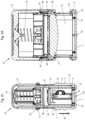
- Fig. 1a-d show an embodiment of the fixing device according to the invention for a self-inking stamp, wherein the fixing device in Fig. 1a in elevation, in Fig. 1b sideways, in Fig. 1c in the cross crack and in Fig. 1d is shown in the floor plan.
- Fig. 2a-d show sectional views of a stamping device, where Fig. 2a the stamping device is in the closed position, Fig. 2b an excerpt from Fig. 2a enlarged, and Fig. 2c-d the stamping device in Show resting position.
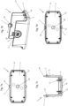
- Fig. 3 shows a self-inking stamp from below (i.e. from the side facing the fixing device in the closed position).
- Fig. 4 shows a stamping device in side view, with the self-inking stamp fixed with the fixing device (closed position).
- Fig. 5a-b show the elevation of a self-inking stamp, the housing of which has a support element, wherein various embodiments of the support element are shown in Fig. 5a and Fig. 5b be illustrated.
- Fig. 6a-b show sectional views of a self-inking stamp, the housing of which has a support element, with different embodiments of the support element in Fig. 6a and Fig. 6b be illustrated.
- Fig. 7a-d show a further embodiment of the fixing device according to the invention for a self-inking stamp, wherein the fixing device in Fig. 7a in a sectional view of the floor plan, in Fig. 7b sideways, in Fig. 7c in a sectional view of the cross section and in Fig. 7d is shown in the floor plan.
- Fig. 8a-b show sectional views of a further embodiment of a stamping device according to the invention in the closed position ( Fig. 8a ) and in rest position ( Fig. 8b ).
- Fig. 1a-d show a fixing device 1 with a substantially rectangular, plate-shaped covering surface 2 for covering a substantially cuboid-shaped self-inking stamp 3.
- the fixing device 1 has protruding in one direction Side walls 4 that border the cover surface 2.
- the long side walls 4 are higher than the wide side walls 4.
- two opposing actuating elements 5 are provided, each having an actuating surface 6.
- the actuating surface 6 is designed in the form of a recess and has grooves to ensure a secure grip for the fingers and prevent slipping.
- the actuating surface 6 is provided with an inscription ("Press") so that it is immediately clear at which point on the fixing device 1 the pressure must be applied to release the locking mechanism.
- two opposing locking elements 7 are provided, the rear sides 8 of which are arranged parallel to one another. These locking elements 7 each have an outwardly directed locking hook 10 on their front side 9 for hooking into a locking lug 11 of an actuating part 12 of the self-inking stamp 3.
- the two actuating elements 5 are arranged between an exposed section of the locking elements 7 and the cover surface 2 in the upper region of the outer sides of the two longitudinal side walls 4.
- Fig. 1a-d As can also be seen, four support elements 15 are arranged on the side of the cover surface 2 facing the self-inking stamp 3 in the closed position for mounting a mounting surface 13 of a housing 14 of the self-inking stamp 3.
- the support elements 15 extend in the direction of the side walls 4 of the fixing device 1, wherein they have a lower height than the side walls 4, so that there is no obstruction to the fixing of the self-inking stamp 3 with the fixing device 1.
- the provision of the support elements 15 ensures a distance between the cover surface 2 and the mounting surface 13 of the housing 14, so that scratching of the stamp plate 16 and soiling of the cover surface 2 by stamping ink adhering to the stamp plate 16 are prevented.
- the side of the cover surface 2 facing the self-inking stamp 3 in the closed position has four guide elements 17 which are provided outside a contact surface 13 of the housing 14 of the self-inking stamp 3, as can be seen from Fig. 1a-d as can also be seen.
- the guide elements 17 are flush with the side walls 4 of the fixing device 1, being higher than the height of the immediately adjacent side walls 4, so that the fixing of the self-inking stamp 3 with the fixing device 1 is not hindered and the guide elements 17 can be received in corresponding recesses 18 of the actuating part 12 of the self-inking stamp 3.
- the cross-sectional area of the guide elements 17 is rectangular and decreases with increasing distance from the cover surface 2. Accordingly, the guide elements 17 are beveled, with the beveled surfaces of two guide elements 17 facing each other. This simplifies the positioning and placement of the contact surface 13 of the housing 14 of the self-inking stamp 3 onto the support elements 15 of the fixing device 1.
- two opposing support ribs 19 are provided on the inner sides, which are arranged normal to the cover surface 2 and extend essentially over the entire height of the side walls 4.
- the fixing device 1 is formed as a single-piece injection-molded part, wherein the filling of the cavity takes place through the injection point 20, the in the center of the cover surface 2. This ensures even filling of the cavity. Ejection was achieved using four ejector pins located in the corner areas of the cover surface 2.
- the injection-molded fixing device 1 is of high quality, warp-free, and free of residual stresses.
- the underside of the cover surface 2 has four feet 21 in the corner areas, ensuring stable positioning on a base.
- a stamping device 22 comprising an embodiment of the fixing device 1 according to the invention and a self-inking stamp 3 is shown in the closed position, and in Fig. 2c-d in rest position.
- Fig. 2b shows an enlarged section 23 of the Fig. 2a .
- the actuating part 12 is slightly curved outwards in the area of the free space 24, so that the free space 24 is only formed in the area of the bulge.
- the fixing device 1 can only be pushed onto the housing 14 of the relieved self-inking stamp 3 in a specific position, thus ensuring an optimal closing effect.
- the housing 14 is pressed into the actuating part 12 by the pressure force applied to the actuating part 12, while the fixing device 1 is pushed onto the housing 14 in the direction of the actuating part 12.
- the locking elements 7 of the fixing device 1 engage with their locking hooks 10 into the corresponding locking lugs 11 of the actuating part 12, which are provided in the free spaces 24. Due to the positive connection, the self-inking stamp 3 is fixed to the fixing device 1 in the closed position, as can be seen from Fig. 2a
- the restoring force of the return spring 25, which is provided in the upper area of the actuating part 12, causes the In the closed position, the pressing force between the fixing device 1 and the self-inking stamp 3, in particular the contact surface 13 of the housing 14, is increased.
- the front side 9 of the locking element 7 rests on the inside of the actuating part 12 of the self-inking stamp 3 in the closed position.
- the rear side 8 of the locking element 7 rests on the outside of the housing 14. Accordingly, there is no free space provided between the rear side 8 of the locking element 7 and the housing 14 of the self-inking stamp 3 into which the locking element 7 could possibly escape when subjected to pressure or softening due to an increase in temperature, if it can no longer withstand the restoring force of the restoring spring 25.
- the closing ability of the fixing device 1 according to the invention is considerably improved by the formation of two contact surfaces of the locking element 7, i.e. its front side 9 and rear side 8, with the actuating part 12 and with the housing 14 of the self-inking stamp 3.
- the user presses together the two opposing actuating elements 5, which are arranged on the longitudinal side walls 4 of the fixing device 1. This pushes the side walls 4 of the fixing device 1, on which the actuating elements 5 and locking elements 7 are arranged, inward, and the locking of the locking elements 7 with the actuating part 12 of the self-inking stamp 3 is released. This enables the fixing device 1 to be subsequently pulled off effortlessly in a displacement direction 26 to make the stamping device 22 ready for use.
- an impression unit 27 is arranged in the actuating part 12 of the self-inking stamp 3, which consists of a plastic, for example polyoxymethylene (POM), since this thermoplastic is characterized by high strength, hardness and rigidity and It can withstand shock loads, such as those that occur when the self-inking stamp 3 is fixed to the fixing device 1 or during the printing process.
- a stamp plate 16 is mounted on the impression unit 27 and, when the self-inking stamp 3 is in the rest position, rests against a stamp pad 28 that is impregnated with stamping ink and provided in a pad container 29.
- the side of the stamp plate 16 used for making a stamp impression is oriented upwards, i.e.
- the impression unit 27 is mounted by means of pin-shaped axle parts 30 so that it can be moved in guide grooves 31 that are provided in the broad side surfaces of the housing 14.
- the impression unit 27 with the stamp plate 16 is adjusted into the printing position via a turning mechanism 32.
- the stamp plate 16 is rotated by 180° by the downward movement of the actuating part 12, so that the side of the stamp plate 16 used for a stamp impression points downwards in the printing position and can produce a stamp impression.
- Fig. 3 shows the self-inking stamp 3 from below (i.e., from the side facing the fixing device 1 in the closed position). Accordingly, the side of the impression unit 27 opposite the stamp plate 16 is visible.
- the contact surface 13 of the housing 14 of the self-inking stamp 3 is partially provided with a sprayed-on rubber layer 33. This rubber layer 33 is provided on the wide-side sections and partially on the long-side sections of the contact surface 13 of the housing 14. It prevents the self-inking stamp 3 from slipping when creating a stamp impression.
- Fig. 3 Four recesses 18 are also visible, which are provided on the side of the actuating part 12 facing the fixing device 1. These recesses 18 are designed in the form of guide strips, which are parallel to the guide grooves 31 for a uniform guidance of the Housing 14 are provided in the actuating part 12 of the self-inking stamp 3. This ensures that the housing 14 does not rotate relative to the actuating part 12 during displacement, but only a linear movement in or against the displacement direction 26 is possible. Furthermore, the guide elements 17 of the fixing device 1 are received in the recesses 18, whereby displacement and/or rotation of the fixing device 1 relative to the self-inking stamp 3 is prevented or at least reduced, thereby further improving the closing ability of the fixing device 1.
- Fig. 4 shows the stamping device 22 according to Fig. 2a-d , comprising the fixing device 1 and the self-inking stamp 3, in a side view in the closed position.
- a locking or blocking element 34 in the form of a button is provided on the broad side surfaces of the actuating part 12.
- Projections 35 of the locking element 34 which protrude into the interior of the housing 14 (as shown in Fig. 2d visible) to fix the housing 14 so that the return spring 25 remains in the compressed position. If properly locked, unintentional release of the impression unit 27 is thus impossible, and easy replacement of the stamp plate 16 is enabled.
- Fig. 5a-b shows the elevation of two further self-inking stamps 3 in the unloaded position.
- the two longitudinal side surfaces of the housing 14 each have a support element 36 in the form of an elongated support rib ( Fig. 5a ) or in the form of a circle ( Fig. 5b ).
- These support elements 36 can be provided instead of the support ribs 19 of the fixing device 1.
- Each of the support elements 36 is positioned so that in the closed position it rests against the rear side 8 of a locking element 7 of the fixing device 1. This creates the contact surface between the locking element 7 and the housing 14 is reduced and a linear or point-shaped contact surface is formed, so that the removal of the fixing device 1 from the self-inking stamp 3 is considerably simplified by the reduced frictional force.
- FIG. 6a-b are sectional views of the Fig. 5a-b The versions of the self-inking stamp shown in the figure are shown.
- Fig. 5a shown embodiment of the support element 36 in the form of an elongated support rib in Fig. 6a
- the Fig. 5b shown embodiment of the support element 36 in the form of a circle in Fig. 6b each shown in side view.
- Fig. 7a-d show a fixing device 1 which corresponds to the Fig. 1a-d shown embodiment.
- the fixing device 1 of the Fig. 7a-d instead of support ribs 19, it has two opposing rollers 37. These rollers 37 are arranged at the lower end of two opposing locking elements 7, ie below exposed sections of the locking elements 7.
- An axis of rotation of the roller 37 is normal to a pulling direction 26 of the fixing device 1 from a self-inking stamp 3, so that pulling can be carried out by a roller movement and scratching of a housing 14 of the self-inking stamp 3 can be prevented.
- a stamping device 22 is in the closed position ( Fig. 8a ) and in rest position ( Fig. 8b ).
- the rollers 37 are arranged below exposed sections of the two locking elements 7 (as in Fig. 7a-d
Landscapes
- Accessory Devices And Overall Control Thereof (AREA)
- Ink Jet (AREA)
- Inking, Control Or Cleaning Of Printing Machines (AREA)
Description
- Die Erfindung betrifft eine Fixiervorrichtung zur Fixierung eines Selbstfärbestempels in einer Schließstellung, die einen Anschlag für eine Aufsetzfläche eines Gehäuses des Selbstfärbestempels und ein mit dem Anschlag verbundenes Rastelement aufweist, wobei eine Vorderseite des Rastelements zum Einrasten an einer Innenseite eines Betätigungsteils des Selbstfärbestempels eingerichtet ist. Weiters betrifft die Erfindung eine Stempelvorrichtung, die die Fixiervorrichtung und einen Selbstfärbestempel aufweist.
- Im Stand der Technik bekannte Selbstfärbestempel umfassen typischerweise ein Betätigungsteil, ein Gehäuse und eine Abdruckeinheit. Dabei weist die Abdruckeinheit ein in einem Kissenbehälter vorgesehenes Stempelkissen zum Einfärben einer Stempelplatte auf. Durch Drücken des Betätigungsteils dreht sich die Stempelplatte um 180° und erzeugt so einen Stempelabdruck.
- In Schließstellung ist der Selbstfärbestempel mit der Fixiervorrichtung fixiert, sodass die Verschiebung des Betätigungsteils gegenüber dem Gehäuse begrenzt ist. Eine im Betätigungsteil vorgesehene Rückstellfeder befindet sich dabei im zusammengedrückten Zustand.
- In Ruhestellung (auch Einfärbestellung) ist der Selbstfärbestempel nicht mit der Fixiervorrichtung fixiert und die Rückstellfeder ist entlastet. Das Gehäuse des Selbstfärbestempels ist in Ruhestellung überwiegend außerhalb des Betätigungsteils des Selbstfärbestempels angeordnet. Im betriebsmäßigen Zustand des Selbstfärbestempels ist das Gehäuse dementsprechend unterhalb des Betätigungsteils angeordnet, und die für einen Stempelabdruck verwendete Seite der Stempelplatte ist nach oben ausgerichtet.
- In Druckstellung ist der Selbstfärbestempel nicht mit der Fixiervorrichtung fixiert und eine Druckkraft wirkt auf das Betätigungsteil des Selbstfärbestempels, sodass sich das Gehäuse im Inneren des Betätigungsteil befindet und die Rückstellfeder zusammengedrückt ist. Die für einen Stempelabdruck verwendete Seite der Stempelplatte zeigt im betriebsmäßigen Zustand des Selbstfärbestempels nach unten und erzeugt einen Abdruck auf einem geeigneten Substrat.
- Allgemein sind Fixiervorrichtungen und Stempel, insbesondere Selbstfärbestempel, die mit einer Fixiervorrichtung fixiert werden, im Stand der Technik bekannt. In den meisten Offenbarungen werden Fixiervorrichtungen, die auf einen Stempel aufgesteckt und abgezogen werden können, beschrieben.
- Die
WO 2016/197172 A1 beschreibt eine Abdeckung, die über die Schmalseite auf einen zusammengedrückten Stempel aufgeschoben wird, wobei die Abdeckung an einem Halteelement des Gehäuses gehalten wird. - Die
EP 2 634 005 B1 undEP 1 796 909 B1 beschreiben eine Abdeckkappe, die über eine Klemmvorrichtung mit der Achse bzw. mit dem Achsstummel der Abdruckeinheit eines Handstempels verbunden wird. Im zusammengedrückten Zustand des Handstempels wird die Abdeckkappe derEP 2 634 005 B1 dabei über Rastelemente mit der Abdruckeinheit verrastet. - Die
EP 0 873 245 B1 offenbart eine Verrastung einer Abdeckung mit einem Stempel an dessen Außenfläche. - Die
WO 2004/091923 A1 offenbart einen Selbstfärbestempel mit Oberschlagfärbung, wobei der Stempel zwei übereinander angeordnete Sockel (SOC1, SOC2) aufweist, welche beide in einem Auslöseelement (AUS) verschiebbar gelagert sind. Ferner ist eine Abdeckung vorgesehen, welche den Sockel derart umschließt, dass eine Bewegung des Sockels relativ zu dem Auslöseelement verhindert ist. Zum Betätigen muss das jeweilige Abdeckelement abgenommen werden, damit eine Relativbewegung möglich ist und die Stempelplatte die zu bestempelnde Fläche berühren kann. - Aus der
CN 207 984 359 U ist ein weiterer Stempel mit einer Abdeckung bekannt. - In den meisten im Stand der Technik beschriebenen Offenbarungen, die eine Verrastung einer Fixiervorrichtung mit einem Stempel beschreiben, erfolgen das Lösen der Verrastung und das Abziehen der Fixiervorrichtung durch das Aufwenden von Zugkraft. Durch diese Krafteinwirkung kann es zu Bauteilversagen kommen, insbesondere zu irreversiblen Verformungen bzw. Ermüdungsbrüchen von Rastelementen, sodass ein Verschließen des Stempels nicht mehr möglich ist.
- Die
AT 523250 A1 CN 112 976 841 A beschreiben eine Abdeckung für einen Stempel, insbesondere einen Selbstfärbestempel, an der zwei gegenüberliegende Betätigungselemente angeordnet sind. Jedes Betätigungselement weist ein Rastelement, etwa einen Rasthaken, auf, der in Schließstellung mit einem Betätigungsteil des Stempels verrastet ist. Durch Zusammendrücken der Betätigungselemente wird der Rasthaken nach innen gedrückt. Durch die Druckbeaufschlagung wird die Verrastung der Abdeckung mit dem Betätigungsteil des Stempels gelöst und die Abdeckung kann kraftlos vom Stempel gezogen werden. Gleichzeitig wechselt der mit der Abdeckung fixierte Stempel unter Wirkung der Federkraft der Rückstellfeder in seine Ruhestellung. Nachteilig ist allerdings, dass sich das Rastelement unter Wirkung der Rückstellfeder relativ leicht von selbst und ungewollt löst, beispielsweise aufgrund von Materialermüdung nach längerer Verwendung oder weil das Material aufgrund höherer Temperaturen, beispielsweise während der Auslieferung und des Transports des neuen Stempels, weicher und damit nachgiebiger wird. - Die im Stand der Technik eingesetzten Fixiervorrichtungen sowie Gehäuse und Betätigungsteile von Selbstfärbestempeln bestehen häufig aus einem Kunststoff mit einer maximalen Dauergebrauchstemperatur von ungefähr 70 bis 90 °C. Bei der Lagerung eines mit einer Fixiervorrichtung fixierten Selbstfärbestempels bei erhöhter Temperatur, etwa während des Transports, kommt es im Glasübergangs- oder Schmelzbereich der Kunststoffe zum Erweichen der Bauteile. Dies führt zu einem signifikanten Abfall der mechanischen Eigenschaften, insbesondere der Festigkeit und Steifigkeit. Damit einher geht bei den bekannten Vorrichtungen eine erhebliche Beeinträchtigung der Schließfähigkeit der Fixiervorrichtung. Die Verrastung der Fixiervorrichtung mit dem Betätigungsteil kann der entgegengerichteten Rückstellkraft der Rückstellfeder des Selbstfärbestempels oft nicht standhalten und wird relativ leicht in einen vorgesehenen Freiraum zwischen Fixiervorrichtung und Gehäuse des Selbstfärbestempels gedrückt, sodass es zum Lösen der Verrastung kommt.
- Es ist daher eine Aufgabe der Erfindung, eine Fixiervorrichtung für einen Selbstfärbestempel bereitzustellen, die eine verbesserte Schließfähigkeit aufweist und diese mit einer höheren Zuverlässigkeit auch bei längerer Verwendung und bei Lagerung im gesamten Dauergebrauchstemperaturbereich der Stempelvorrichtung beibehält.
- Die Erfindung betrifft eine Fixiervorrichtung zur Fixierung eines Selbstfärbestempels in einer Schließstellung, die dadurch gekennzeichnet ist, dass das Rastelement nicht nur eingerichtet ist, um mit der Vorderseite des Rastelements an der Innenseite des Betätigungsteils des Selbstfärbestempels einzurasten, sondern auch, um mit einer der Innenseite des Betätigungsteils gegenüberliegenden Rückseite des Rastelements am Gehäuse des mit der Fixiervorrichtung fixierten Selbstfärbestempels anzuliegen. Die Erfindung betrifft weiters eine Stempelvorrichtung, wobei der Selbstfärbestempel mit der Fixiervorrichtung in der Schließstellung fixiert ist.
- Die Erfindung basiert auf der Erkenntnis, dass durch das Vorsehen des Rastelements, das mit seiner Rückseite an der Außenseite des Gehäuses des mit der Fixiervorrichtung fixierten Selbstfärbestempels anliegt, die zuverlässige Schließfähigkeit der Fixiervorrichtung im gesamten Dauergebrauchstemperaturbereich der Stempelvorrichtung erheblich verbessert wird.
- Alle offenbarten Ausführungsformen der vorliegenden Erfindung sind miteinander verknüpft, und jede offenbarte Ausführungsform und/oder jedes offenbarte charakteristische Merkmal können miteinander und auch als beliebige Kombination von zwei oder mehreren Ausführungsformen und/oder Ausführungsmerkmalen kombiniert werden.
- Für die Zwecke dieser Offenbarung beziehen sich Angaben wie "oben", "unten", "oberhalb", "unterhalb", etc. auf den bestimmungsgemäßen Betriebszustand des Selbstfärbestempels, um einen Abdruck auf einem geeigneten Substrat, auf dem die Stempelfarbe haftet (beispielsweise Papier), zu erzeugen.
- Die Fixiervorrichtung weist ein Rastelement auf. Ein Abschnitt dieses Rastelements kann beispielsweise aufgrund einer exponierten Stellung leicht verformbar sein. Das Rastelement rastet mit seiner Vorderseite an der Innenseite des Betätigungsteils des Selbstfärbestempels ein, wobei ein Freiraum etwa in Form einer Nut an der Innenseite des Betätigungsteils vorgesehen werden kann, in den das Rastelement aufgenommen wird. Durch das Ausbilden einer formschlüssigen Verbindung zwischen dem Rastelement und dem Betätigungsteil wird der Selbstfärbestempel durch die Fixiervorrichtung in Schließstellung fixiert. Das Rastelement ist mit dem Anschlag der Fixiervorrichtung verbunden, auf dem in Verwendung die Aufsetzfläche des Gehäuses des Selbstfärbestempels in Schließstellung aufliegt. Die Vorderseite des Rastelements liegt in dieser Schließstellung an der Innenseite des Betätigungsteils des Selbstfärbestempels an. Zusätzlich dazu liegt die Rückseite des Rastelements an der Außenseite des Gehäuses an. Das Rastelement steht somit in beidseitigem Kontakt mit dem Selbstfärbestempel. Dementsprechend ist zwischen der Rückseite des Rastelements und dem Gehäuse des Selbstfärbestempels kein Freiraum vorgesehen, in welchen das Rastelement bei Druckbeaufschlagung bzw. Erweichung durch Temperaturerhöhung gegebenenfalls ausweichen könnte, wenn es der Rückstellkraft der Rückstellfeder nicht mehr aus eigener Kraft standhalten kann. Das Rastelement wird vielmehr zwischen dem Betätigungsteil und dem Gehäuse des Selbstfärbestempels eingeklemmt. Zum Lösen der Verrastung wird daher nicht nur das Rastelement, sondern auch das Gehäuse deformiert. Die Schließfähigkeit der Fixiervorrichtung wird dadurch erheblich verbessert.
- Die Fixiervorrichtung kann aus Kunststoff bestehen, etwa aus Acrylnitril-Butadien-Styrol (ABS), da dieser Thermoplast gute mechanische Eigenschaften und insbesondere eine gute Elastizität aufweist, was für das Verformen bzw. Verbiegen der Fixiervorrichtung, insbesondere des Rastelements, vorteilhaft ist. Das Gehäuse des Selbstfärbestempels besteht ebenfalls aus einem Kunststoff, der aus ästhetischen Gründen transparent sein kann. Hierfür eignen sich aufgrund ihrer Transparenz sowie hoher Festigkeit und Schlagzähigkeit etwa die Thermoplaste Polycarbonat (PC) oder Polymethylmethacrylat (PMMA), wobei sich PMMA insbesondere aufgrund seiner ausgezeichneten Kratzfestigkeit als sehr geeignet erweist. Es wurde gefunden, dass durch Ausbilden des beidseitigen Kontakts des Rastelements mit dem Selbstfärbestempel die Schließfähigkeit der erfindungsgemäßen Fixiervorrichtung im gesamten Dauergebrauchstemperaturbereich der eingesetzten Kunststoffe der Fixiervorrichtung und des Selbstfärbestempels, d.h. auch bei erhöhter Temperatur, erheblich verbessert wird.
- Das Rastelement der Fixiervorrichtung kann einen Rasthaken aufweisen, um die Haltekraft der Fixiervorrichtung weiter zu verbessern. Der Rasthaken kann auf der Vorderseite des Rastelements in dessen exponiertem Abschnitt angeordnet sein, sodass der Rasthaken im Schließzustand in einer im Inneren des Betätigungsteils des Selbstfärbestempels vorgesehenen Rastnase einrastet. Aufgrund der normal zur Rückstellkraft der Rückstellfeder angeordneten Kontaktfläche des Rasthakens mit der Innenseite des Betätigungsteils wird eine besonders stabile formschlüssige Verbindung ausgebildet und die Schließfähigkeit der Fixiervorrichtung ist besonders hoch.
- Die Rückseite des Rastelements der Fixiervorrichtung kann weiters ein Stützelement aufweisen. In Schließstellung liegt das Stützelement an der Außenseite des Gehäuses an. Das Stützelement kann in unterschiedlichen geometrischen Formen ausgebildet sein, wie zum Beispiel in Form eines Kreises, einer Ellipse, oder in länglicher Form, insbesondere in Form einer Stützrippe. Durch das am Rastelement vorgesehene Stützelement wird einerseits die lokale Steifigkeit der Fixiervorrichtung erhöht. Dadurch ist es möglich, die Wandstärke des Rastelements zu verringern, um Material zu sparen. Erstreckt sich das Stützelement über den Bereich zwischen dem Anschlag für die Aufsetzfläche des Gehäuses des Selbstfärbestempels und dem Rastelement, kann auch dieser Bereich durch die Versteifung des Stützelements mit einer dünneren Wandstärke ausgeführt werden. Weiters wird durch das Vorsehen eines Stützelements die Kontaktfläche zwischen dem Rastelement und dem Selbstfärbestempel verringert. Durch das Verringern der Kontaktfläche wird die Schließfähigkeit der Fixiervorrichtung nicht beeinträchtigt, aber das Abziehen der Fixiervorrichtung vom Selbstfärbestempel wird durch die reduzierte Reibungskraft aufgrund der verringerten Kontaktfläche erheblich erleichtert.
- Anstelle des Vorsehens eines Stützelements am Rastelement, oder zusätzlich dazu, kann an der Außenseite des Gehäuses des Selbstfärbestempels ein Stützelement vorgesehen sein. Dieses Stützelement kann in unterschiedlichen geometrischen Formen ausgebildet sein, wie zum Beispiel in Form eines Kreises, einer Ellipse, oder in länglicher Form, insbesondere in Form einer Stützrippe. Zum einen erhöht das Stützelement die lokale Steifigkeit des Gehäuses. Zum anderen liegt das Stützelement in Schließstellung an der Rückseite des Rastelements der Fixiervorrichtung an und verringert dadurch die Kontaktfläche, sodass das Abziehen der Fixiervorrichtung vom Selbstfärbestempel durch die verringerte Reibungskraft erheblich vereinfacht wird.
- Das Vorsehen eines Stützelements am Rastelement der Fixiervorrichtung hat gegenüber dem Vorsehen eines Stützelements am Gehäuse des Selbstfärbestempels den Vorteil, dass keine Anpassung des Formwerkzeugs für die Herstellung des Gehäuses, die etwa mittels Spritzgießen erfolgt, erforderlich ist. Umgekehrt kann es durch ein am Rastelement der Fixiervorrichtung vorgesehenes Stützelement beim Abziehen der Fixiervorrichtung vom Selbstfärbestempel zum Zerkratzen des Gehäuses kommen. Dies wird verhindert, indem das Stützelement stattdessen am Gehäuse des Selbstfärbestempels vorgesehen wird, sodass diese Ausführung aus ästhetischen Gründen vorteilhaft ist.
- Die Rückseite des Rastelements der Fixiervorrichtung kann eine Rolle aufweisen. Diese kann anstelle eines Stützelements vorgesehen sein. Eine Drehachse der Rolle steht dabei normal auf eine Abziehrichtung der Fixiervorrichtung vom Selbstfärbestempel. Durch die verringerte Reibung (Rollreibung statt Gleitreibung) wird das Abziehen der Fixiervorrichtung erheblich vereinfacht und kann durch eine Rollbewegung erfolgen. Somit wird das Auftreten von Gleitreibung verringert bzw. gänzlich verhindert, sodass ein Zerkratzen der Außenseite des Gehäuses des Selbstfärbestempels vermieden werden kann. In einer vorteilhaften Ausführungsform ist die Rolle am unteren Ende des Rastelements vorgesehen, d.h. unterhalb des exponierten Abschnitts des Rastelements. Somit wird das Lösen der Verrasterung durch Druckbeaufschlagung durch die Anwesenheit der Rolle nicht beeinträchtigt. Durch die Rolle wird weiters die Kontaktfläche zwischen der Fixiervorrichtung und dem Selbstfärbestempel in Schließstellung verringert. Es kann auch nur eine Linienberührung entlang einer Höhe der zylinderförmigen Rolle mit der Außenseite des Gehäuses des Selbstfärbestempels auftreten. Das vereinfacht das Abziehen weiter. Gleichzeitig wird durch die Rolle eine ausreichend hohe Steifigkeit bereitgestellt, sodass sich das Rastelement auch in dieser Ausführungsform nicht leicht von selbst und ungewollt lösen kann.
- Der Anschlag der Fixiervorrichtung kann als Abdeckfläche zum Abdecken der Aufsetzfläche des Gehäuses des Selbstfärbestempels ausgebildet sein. Durch die einwirkende Rückstellkraft der Rückstellfeder wird eine hohe Presskraft zwischen der Abdeckfläche der Fixiervorrichtung und der Aufsetzfläche des Gehäuses erreicht, sodass eine gute Abdichtung erreicht wird. Zum Abdecken der Aufsetzfläche des Gehäuses des Selbstfärbestempels kann sich die Abdeckfläche der Fixiervorrichtung über die gesamte Aufsetzfläche des Gehäuses erstrecken. Dies ermöglicht es, das Innere des Selbstfärbestempels staubdicht zu verschließen und die aus der Rückstellkraft der Rückstellfeder resultierende Presskraft in Schließstellung gleichmäßig auf die Kontaktfläche des Selbstfärbestempels mit der Fixiervorrichtung aufzubringen. Außerdem wird durch das vollständige Abdecken der Aufsetzfläche des Gehäuses des Selbstfärbestempels ein ungewolltes Verschmutzen, etwa von Gegenständen, mit Stempelfarbe vermieden.
- Der Grundriss des Selbstfärbestempels kann beispielsweise rund, elliptisch oder trapezförmig, insbesondere rechteckig, sein. Um etwa eine Aufsetzfläche des Gehäuses des Selbstfärbestempels mit einem im Wesentlichen trapezförmigen, insbesondere rechteckigen, Grundriss gut zu verschließen, kann die Abdeckfläche der Fixiervorrichtung ebenfalls im Wesentlichen trapezförmig, insbesondere rechteckig, sein, um die Aufsetzfläche des Gehäuses zur Gänze abzudecken.
- Die Fixiervorrichtung kann weiters Seitenwände aufweisen. Weist die Fixiervorrichtung eine Abdeckfläche auf, grenzen die Seitenwände an die Abdeckfläche an und stehen etwa normal auf die Abdeckfläche. Seitenwände verbessern nicht nur die Benutzerfreundlichkeit, insbesondere das Handling der Fixiervorrichtung, sondern auch die Schließfähigkeit der Fixiervorrichtung, da die Seitenwände der Fixiervorrichtung in Schließstellung mit den Seitenwänden des Gehäuses des Selbstfärbestempels teilweise überlappen. Dadurch wird die Kontaktfläche zwischen Fixiervorrichtung und Selbstfärbestempel vergrößert und die Freiheitsgrade der Fixiervorrichtung werden eingeschränkt, sodass ein Verdrehen und/oder Verschieben der Fixiervorrichtung gegenüber dem Selbstfärbestempel reduziert wird und die Schließfähigkeit somit weiter verbessert wird. In Schließstellung können die Seitenwände der Fixiervorrichtung bündig mit den Seitenwänden des Betätigungsteils des Selbstfärbestempels abschließen, sodass sich das Gehäuse des Selbstfärbestempels in Schließstellung zur Gänze im Inneren der Stempelvorrichtung befindet. Dies verleiht der Stempelvorrichtung nicht nur einen ästhetischen Eindruck, sondern schützt das Innere der Stempelvorrichtung sehr gut gegen das Eintreten von Staub.
- Weist die Fixiervorrichtung Seitenwände auf, können unterschiedliche Abschnitte der Seitenwände unterschiedliche Höhen aufweisen. Beispielsweise können im Fall einer im Wesentlichen rechteckigen Ausführung die breitseitigen Seitenwände eine geringere Höhe aufweisen als die längsseitigen Seitenwände. Dadurch wird eine vergleichsweise große Überlappung der längsseitigen Seitenwände der Fixiervorrichtung mit der Außenseite des Gehäuses des Selbstfärbestempels erreicht. Damit einher geht eine korrespondierende unterschiedliche Höhe der Seitenwände des Betätigungsteils mit im Wesentlichen rechteckiger Querschnittsfläche, das an Abschnitten der breitseitigen Seitenwände höher ist als an Abschnitten der längsseitigen Seitenwände, sodass in Schließstellung ein bündiger Abschluss der Seitenwände der Fixiervorrichtung mit den Seitenwänden des Betätigungsteils des Selbstfärbestempels sichergestellt ist. Die vergleichsweise geringe Höhe der längsseitigen Seitenwände des Betätigungsteils ermöglicht es, dass der Kissenbehälter, in dem sich das Stempelkissen befindet, in Ruhestellung außerhalb des Betätigungsteils angeordnet ist und aus dem Gehäuse des Selbstfärbestempels herausgedrückt und ausgetauscht werden kann. Die vergleichsweise hohen breitseitigen Seitenwände des Betätigungsteils tragen und schützen wiederum die Achslager der Abdruckeinheit, die etwa mittels zapfenförmigen Achsteilen in Führungsnuten, die in den breitseitigen Seitenflächen des Gehäuses des Selbstfärbestempels vorgesehen sein können, relativ zum Gehäuse linear verschiebbar ist.
- Die Fixiervorrichtung kann zwei Rastelemente aufweisen, die einander gegenüberliegen. Dabei sind die Rückseiten der beiden Rastelemente, die zum Einrasten an der Innenseite des Betätigungsteils des Selbstfärbestempels vorgesehen sind, einander zugewandt. Das Vorsehen von zwei einander gegenüberliegenden Rastelementen, deren Rückseiten parallel zueinander angeordnet sind, und die einander insbesondere in Bezug auf eine zentrale Achse der Rückstellfeder des zu fixierenden Stempels gegenüberliegen, ist besonders vorteilhaft für die Schließfähigkeit der Fixiervorrichtung, da die Rückstellkraft der Rückstellfeder dabei gleichmäßig über die zwei Rastelemente in die Fixiervorrichtung eingeleitet wird. Bei einer Fixiervorrichtung mit einer im Wesentlichen rechteckigen Abdeckfläche können zwei Rastelemente an den beiden Längsseiten der Abdeckfläche vorgesehen sein. Weist die Fixiervorrichtung Seitenwände auf, können zwei Rastelemente an den beiden längsseitigen Seitenwänden vorgesehen sein. Da sich die längsseitigen Seitenwände der Fixiervorrichtung in der Mitte, d.h. auf der Hälfte der jeweiligen Längsseite, naturgemäß besonders leicht deformieren lassen, ist das Vorsehen von zwei Rastelementen in der Mitte der längsseitigen Seitenwände der Fixiervorrichtung besonders gut zum Verschließen eines im Wesentlichen quaderförmigen Selbstfärbestempels geeignet. Im Fall von zwei Rastelementen kann jedes der Rastelemente ein Stützelement aufweisen, bzw. können zwei Stützelemente an der Außenseite des Gehäuses des Selbstfärbestempels, die in Schließstellung an den jeweiligen Rückseiten der Rastelemente anliegen, vorgesehen sein. Dies ermöglicht ein gleichmäßiges Lösen der beidseitigen Verrastung und ein gleichmäßiges Abziehen der Fixiervorrichtung vom Selbstfärbestempel.
- Die Fixiervorrichtung kann zwischen dem Anschlag für die Aufsetzfläche des Gehäuses des Selbstfärbestempels und dem Rastelement ein Betätigungselement aufweisen, das etwa kreisförmig oder elliptisch, und/oder in Form einer Mulde ausgeformt sein kann und die Benutzerfreundlichkeit verbessert, da somit einfach ersichtlich ist, wie die Fixiervorrichtung vom Selbstfärbestempel abgenommen werden kann. Das Betätigungselement kann auch zwischen dem Anschlag für die Aufsetzfläche des Gehäuses des Selbstfärbestempels und dem exponierten Bereich des Rastelements angeordnet sein. Durch Drücken auf das Betätigungselement wird die Verrastung des Rastelements an der Innenseite des Betätigungsteils des Selbstfärbestempels gelöst. Das Betätigungselement kann eine Rutschsicherung, beispielsweise in Form von Rillen oder Symbolen, aufweisen, um einen sicheren Halt für die Finger zu gewährleisten. Weiters kann das Betätigungselement mit einer Aufschrift versehen sein (etwa "Drücken" oder "Press"), sodass für den Benutzer sofort ersichtlich ist, an welcher Stelle der Fixiervorrichtung der Druck zum Lösen der Verrastung aufgebracht werden muss. Weist die Fixiervorrichtung Seitenwände auf, kann das Betätigungselement an den Seitenwänden vorgesehen sein. Auch zwei einander gegenüberliegende, parallel zueinander angeordnete Betätigungselemente können vorgesehen sein, was die Benutzerfreundlichkeit weiter verbessert, da die entsprechenden geeigneten Positionen zum Zusammendrücken der Fixiervorrichtung somit einfach ersichtlich sind.
- Die Abdeckfläche der Fixiervorrichtung kann ein Abstützelement aufweisen, auf dem die Aufsetzfläche des Gehäuses in Schließstellung aufliegt. Durch das Vorsehen eines Abstützelements wird in Schließstellung ein Abstand zwischen der Abdeckfläche der Fixiervorrichtung und der Aufsetzfläche des Gehäuses gewährleistet. Da die für einen Stempeldruck verwendete Seite der Stempelplatte in Schließstellung der Abdeckfläche zugewandt ist, werden durch das Vorsehen dieses Abstands ein Verschmutzen der Abdeckfläche durch an der Stempelplatte haftende Stempelfarbe sowie ein Zerkratzen der Stempelplatte verhindert. Es können auch vier Abstützelemente vorgesehen sein, die beispielsweise eine rechteckige Querschnittsfläche aufweisen und in regelmäßigen Abständen über den Umfang der aufzunehmenden Abdeckfläche des Gehäuses des Selbstfärbestempels verteilt sind. Die Aufsetzfläche des Gehäuses liegt in dieser Ausführungsform gleichmäßig und fest auf den Abstützelementen auf, sodass keine Bewegung des Gehäuses relativ zur Fixiervorrichtung möglich ist. Weist die Fixiervorrichtung Seitenwände auf, kann das Abstützelement bündig an die Seitenwände angrenzen, was die Stabilität des Abstützelements verbessert und die Herstellung im Spritzgießprozess vereinfacht.
- Die Abdeckfläche der Fixiervorrichtung kann auf der dem Selbstfärbestempel in Schließstellung zugewandten Seite ein Führungselement aufweisen. Das Führungselement ist dabei außerhalb der vom Anschlag der Fixiervorrichtung aufzunehmenden Aufsetzfläche des Gehäuses angeordnet, sodass es für das Fixieren des Selbstfärbestempels mit der Fixiervorrichtung nicht hinderlich ist. Das Führungselement weist etwa eine runde oder rechteckige Querschnittsfläche auf und wird in Schließstellung in einer korrespondierenden Ausnehmung des Betätigungsteils des Selbstfärbestempels aufgenommen. Durch das Einwirken äußerer Kräfte, beispielsweise beim Transport, kann es zu einer relativen Verschiebung und/oder Verdrehung der Fixiervorrichtung gegenüber dem Selbstfärbestempel kommen, was nicht nur die Schließfähigkeit beeinträchtigen, sondern auch die Lebensdauer der Stempelvorrichtung verringern und zu Bauteilversagen führen kann. Durch die Aufnahme des Führungselements in der korrespondierenden Ausnehmung des Betätigungsteils wird ein relatives Verschieben und/oder Verdrehen der Fixiervorrichtung gegenüber dem Selbstfärbestempel verhindert oder zumindest verringert und die Schließfähigkeit der Fixiervorrichtung wird weiter verbessert. Weiters werden das Positionieren und Aufsetzen der Aufsetzfläche des Gehäuses des Selbstfärbestempels auf dem Anschlag der Fixiervorrichtung durch das Führungselement vereinfacht.
- Die Ausnehmung des Betätigungsteils, in die bei der obigen Variante die Aufnahme des Führungselements erfolgt, kann gleichzeitig für die Führung des Gehäuses im Betätigungsteil des Selbstfärbestempels vorgesehen sein. Somit wird die Anzahl der Ausnehmungen an der der Fixiervorrichtung in Schließstellung zugewandten Seite des Betätigungsteils des Selbstfärbestempels geringgehalten. Dadurch werden nicht nur eine höhere Steifigkeit und Festigkeit des Betätigungsteils beibehalten, sondern aufgrund der größeren zur Verfügung stehenden Kontaktfläche zwischen dem Betätigungsteil und der Abdeckfläche der Fixiervorrichtung wird auch die Haftreibungskraft erhöht und dementsprechend die Schließfähigkeit der Fixiervorrichtung verbessert.
- Weist die Fixiervorrichtung Seitenwände auf, ist das Führungselement naturgemäß höher als der Abschnitt einer Seitenwand, der sich in unmittelbarer Nähe zum Führungselement befindet, sodass die Aufnahme des Führungselements in einer korrespondierenden Ausnehmung des Betätigungsteils des Selbstfärbestempels nicht durch den Abschnitt der Seitenwand behindert wird. Das Führungselement kann bündig an die Seitenwand angeschlossen sein. Dies vereinfacht nicht nur die Herstellung im Spritzgießprozess, sondern ist auch vorteilhaft für die Stabilität des Führungselements.
- Die Abdeckfläche der Fixiervorrichtung kann auf der dem Selbstfärbestempel in Schließstellung zugewandten Seite außerhalb der aufzunehmenden Aufsetzfläche des Gehäuses insbesondere zwei, drei oder vier Führungselemente aufweisen, die in Schließstellung in korrespondierenden Ausnehmungen des Betätigungsteils des Selbstfärbestempels aufgenommen werden. Die Führungselemente können dabei über den Umfang der Abdeckfläche verteilt sein. Bei einer viereckigen Abdeckfläche können etwa vier Führungselemente in den vier Eckbereichen der Abdeckfläche angeordnet sein. Durch die zwei, drei oder vier Führungselemente wird ein Verschieben und/oder Verdrehen der Fixiervorrichtung weitgehend verhindert. Das Vorsehen mehrerer Führungselemente vereinfacht auch das Positionieren und Aufsetzen der Aufsetzfläche des Gehäuses des Selbstfärbestempels auf dem Anschlag der Fixiervorrichtung. Dabei können auch Führungselemente mit einander zugewandten Abschrägungen vorgesehen werden, die die Aufsetzfläche des Gehäuses des Selbstfärbestempels dabei unterstützen, in die für das Fixieren notwendige Position zu gleiten.
- Die Erfindung wird nachstehend anhand von Figurenbeschreibungen bevorzugter Ausführungsformen, auf die sie jedoch nicht beschränkt werden soll, weiter erläutert. Es wird darauf hingewiesen, dass die Figuren bzw. deren Bestandteile zum besseren Verständnis teilweise unmaßstäblich dargestellt sind.
-
Fig. 1a-d zeigen eine Ausführungsform der erfindungsgemäßen Fixiervorrichtung für einen Selbstfärbestempel, wobei die Fixiervorrichtung inFig. 1a im Aufriss, inFig. 1b seitlich, inFig. 1c im Kreuzriss und inFig. 1d im Grundriss dargestellt ist. -
Fig. 2a-d zeigen Schnittdarstellungen einer Stempelvorrichtung, wobeiFig. 2a die Stempelvorrichtung in Schließstellung zeigt,Fig. 2b einen Ausschnitt ausFig. 2a vergrößert darstellt, undFig. 2c-d die Stempelvorrichtung in Ruhestellung zeigen. -
Fig. 3 zeigt einen Selbstfärbestempel von unten (d.h. von der der Fixiervorrichtung in Schließstellung zugewandten Seite). -
Fig. 4 zeigt eine Stempelvorrichtung in seitlicher Ansicht, wobei der Selbstfärbestempel mit der Fixiervorrichtung fixiert ist (Schließstellung). -
Fig. 5a-b zeigen den Aufriss eines Selbstfärbestempels, dessen Gehäuse ein Stützelement aufweist, wobei verschiedene Ausführungsformen des Stützelements inFig. 5a und Fig. 5b veranschaulicht werden. -
Fig. 6a-b zeigen Schnittdarstellungen eines Selbstfärbestempels, dessen Gehäuse ein Stützelement aufweist, wobei verschiedene Ausführungsformen des Stützelements inFig. 6a und Fig. 6b veranschaulicht werden. -
Fig 7a-d zeigen eine weitere Ausführungsform der erfindungsgemäßen Fixiervorrichtung für einen Selbstfärbestempel, wobei die Fixiervorrichtung inFig. 7a in einer Schnittdarstellung des Grundrisses, inFig. 7b seitlich, inFig. 7c in einer Schnittdarstellung des Kreuzrisses und inFig. 7d im Grundriss dargestellt ist. -
Fig. 8a-b zeigen Schnittdarstellungen einer weiteren Ausführungsform einer erfindungsgemäßen Stempelvorrichtung in Schließstellung (Fig. 8a ) und in Ruhestellung (Fig. 8b ). -
Fig. 1a-d zeigen eine Fixiervorrichtung 1 mit einer im Wesentlichen rechteckigen, plattenförmigen Abdeckfläche 2 zum Abdecken eines im Wesentlichen quaderförmigen Selbstfärbestempels 3. Bei anderen geometrischen Ausführungen des Selbstfärbestempels 3 ist eine entsprechende Anpassung der geometrischen Abmessungen der Fixiervorrichtung 1 nötig. Die Fixiervorrichtung 1 weist in einer Richtung vorragende Seitenwände 4 auf, die an die Abdeckfläche 2 angrenzen. Die längsseitigen Seitenwände 4 sind dabei höher als die breitseitigen Seitenwände 4. In der Mitte der Außenseiten der längsseitigen Seitenwände 4 sind zwei einander gegenüberliegende Betätigungselemente 5 vorgesehen, die eine Betätigungsfläche 6 aufweisen. Die Betätigungsfläche 6 ist in Form einer Mulde ausgebildet und weist Rillen auf, um einen sicheren Halt für die Finger zu gewährleisten und Abrutschen zu vermeiden. Weiters ist die Betätigungsfläche 6 mit einer Aufschrift ("Press") versehen, sodass sofort ersichtlich ist, an welcher Stelle der Fixiervorrichtung 1 der Druck zum Lösen der Verrastung aufgebracht werden muss. An den Außenseiten der zwei längsseitigen Seitenwänden 4 sind zwei einander gegenüberliegende Rastelemente 7 vorgesehen, deren Rückseiten 8 parallel zueinander angeordnet sind. Diese Rastelemente 7 weisen an ihrer Vorderseite 9 jeweils einen nach außen gerichteten Rasthaken 10 zum Einhaken in einer Rastnase 11 eines Betätigungsteils 12 des Selbstfärbestempels 3 auf. Die beiden Betätigungselemente 5 sind dabei zwischen einem exponierten Abschnitt der Rastelemente 7 und der Abdeckfläche 2 im oberen Bereich der Außenseiten der zwei längsseitigen Seitenwände 4 angeordnet. - Wie aus
Fig. 1a-d weiters ersichtlich, sind zum Aufsetzen einer Aufsetzfläche 13 eines Gehäuses 14 des Selbstfärbestempels 3 vier Abstützelemente 15 an der dem Selbstfärbestempel 3 in Schließstellung zugewandten Seite der Abdeckfläche 2 angeordnet. Die Abstützelemente 15 erstrecken sich in Richtung der Seitenwände 4 der Fixiervorrichtung 1, wobei sie eine geringere Höhe aufweisen als die Seitenwände 4, sodass es zu keiner Behinderung des Fixierens des Selbstfärbestempels 3 mit der Fixiervorrichtung 1 kommt. Durch das Vorsehen der Abstützelemente 15 wird ein Abstand zwischen der Abdeckfläche 2 und der Aufsetzfläche 13 des Gehäuses 14 gewährleistet, sodass ein Zerkratzen der Stempelplatte 16 und ein Verschmutzen der Abdeckfläche 2 durch an der Stempelplatte 16 haftende Stempelfarbe verhindert werden. - Die dem Selbstfärbestempel 3 in Schließstellung zugewandte Seite der Abdeckfläche 2 weist vier Führungselemente 17 auf, die außerhalb einer Aufsetzfläche 13 des Gehäuses 14 des Selbstfärbestempels 3 vorgesehen sind, wie aus
Fig. 1a-d weiters ersichtlich ist. Die Führungselemente 17 schließen bündig an die Seitenwände 4 der Fixiervorrichtung 1 an, wobei sie höher sind als die Höhe der jeweils unmittelbar angrenzenden Seitenwände 4, sodass das Fixieren des Selbstfärbestempels 3 mit der Fixiervorrichtung 1 nicht behindert wird und die Führungselemente 17 in korrespondierenden Ausnehmungen 18 des Betätigungsteils 12 des Selbstfärbestempels 3 aufgenommen werden können. Die Querschnittsfläche der Führungselemente 17 ist rechteckig und nimmt mit zunehmender Entfernung von der Abdeckfläche 2 ab. Dementsprechend sind die Führungselemente 17 abgeschrägt, wobei die abgeschrägten Flächen zweier Führungselemente 17 einander jeweils zugewandt sind. Dies vereinfacht das Positionieren und Aufsetzen der Aufsetzfläche 13 des Gehäuses 14 des Selbstfärbestempels 3 auf die Abstützelemente 15 der Fixiervorrichtung 1. - An den längsseitigen Seitenwänden 4 der Fixiervorrichtung 1 sind, wie in
Fig. 1b dargestellt ist, an den Innenseiten zwei einander gegenüberliegende Stützrippen 19 vorgesehen, die normal zur Abdeckfläche 2 angeordnet sind und sich im Wesentlichen über die gesamte Höhe der Seitenwände 4 erstrecken. Durch das Vorsehen der Stützrippen 19 wird die Kontaktfläche zwischen der Rückseite des Rastelements 7 und der Außenseite des Gehäuses 14 des Selbstfärbestempels 3 verringert. Anstelle einer flächenförmigen Kontaktfläche liegt eine linienförmige Kontaktfläche vor, was die Reibungskraft verringert und zu einem einfacheren Abziehen der Fixiervorrichtung 1 vom Selbstfärbestempel 3 führt. - Wie aus
Fig. 1a-d auch ersichtlich ist, ist die Fixiervorrichtung 1 einteilig als Spritzgießteil ausgebildet, wobei das Befüllen der Kavität durch den Anspritzpunkt 20, der in der Mitte der Abdeckfläche 2 vorgesehen ist. Dadurch wird ein gleichmäßiges Befüllen der Kavität gewährleistet. Das Auswerfen erfolgte mithilfe von vier in den Eckbereichen der Abdeckfläche 2 angeordneten Auswerferstiften. Die spritzgegossene Fixiervorrichtung 1 ist hochqualitativ, verzugsfrei und frei von Eigenspannungen. Die Unterseite der Abdeckfläche 2 weist in den Eckbereichen vier Füße 21 auf, was eine stabile Positionierung auf einer Unterlage gewährleistet. - In
Fig. 2a wird eine Stempelvorrichtung 22 aufweisend eine Ausführungsform der erfindungsgemäßen Fixiervorrichtung 1 und einen Selbstfärbestempel 3 in Schließstellung gezeigt, und inFig. 2c-d in Ruhestellung.Fig. 2b zeigt einen vergrößerten Ausschnitt 23 derFig. 2a . Im Inneren der längsseitigen Seitenflächen des Betätigungsteils 12 des Selbstfärbestempels 3 sind zwei einander gegenüberliegende Freiräume 24 ausgebildet, die eine Rastnase 11 aufweisen, in denen die mit Rasthaken 10 versehenen Rastelemente 7 der Fixiervorrichtung 1 in Schließstellung einrasten. Das Betätigungsteil 12 ist dabei im Bereich des Freiraums 24 leicht nach außen gewölbt, sodass der Freiraum 24 nur im Bereich der Auswölbung ausgebildet ist. Dadurch kann die Fixiervorrichtung 1 nur in einer bestimmten Position auf das Gehäuse 14 des entlasteten Selbstfärbestempels 3 aufgeschoben werden, sodass eine optimale Schließwirkung sichergestellt wird. Das Gehäuse 14 wird durch auf das Betätigungsteil 12 aufgebrachte Druckkraft in das Betätigungsteil 12 hineingedrückt, während die Fixiervorrichtung 1 in Richtung des Betätigungsteils 12 auf das Gehäuse 14 aufgeschoben wird. Die Rastelemente 7 der Fixiervorrichtung 1 rasten mit ihren Rasthaken 10 in die korrespondierenden Rastnasen 11 des Betätigungsteils 12, die in den Freiräumen 24 vorgesehen sind, ein. Durch die formschlüssige Verbindung wird der Selbstfärbestempel 3 mit der Fixiervorrichtung 1 in Schließstellung fixiert, wie ausFig. 2a ersichtlich ist. Durch die einwirkende Rückstellkraft der Rückstellfeder 25, die im oberen Bereich des Betätigungsteils 12 vorgesehen ist, wird in der Schließstellung die Presskraft zwischen der Fixiervorrichtung 1 und dem Selbstfärbestempel 3, insbesondere der Aufsetzfläche 13 des Gehäuses 14, erhöht. - Wie in
Fig. 2b vergrößert dargestellt ist, liegt die Vorderseite 9 des Rastelements 7 in Schließstellung an der Innenseite des Betätigungsteils 12 des Selbstfärbestempels 3 an. Zusätzlich dazu liegt die Rückseite 8 des Rastelements 7 an der Außenseite des Gehäuses 14 an. Dementsprechend ist zwischen der Rückseite 8 des Rastelements 7 und dem Gehäuse 14 des Selbstfärbestempels 3 kein Freiraum vorgesehen, in welchen das Rastelement 7 bei Druckbeaufschlagung bzw. Erweichung durch Temperaturerhöhung gegebenenfalls ausweichen könnte, wenn es der Rückstellkraft der Rückstellfeder 25 nicht mehr standhalten kann. Die Schließfähigkeit der erfindungsgemäßen Fixiervorrichtung 1 wird durch das Ausbilden von zwei Kontaktflächen des Rastelements 7, d.h. dessen Vorderseite 9 und Rückseite 8, mit dem Betätigungsteil 12 bzw. mit dem Gehäuse 14 des Selbstfärbestempels 3 erheblich verbessert. - Um die Verrastung zu lösen, drückt der Nutzer die zwei einander gegenüberliegenden Betätigungselemente 5, die an den längsseitigen Seitenwänden 4 der Fixiervorrichtung 1 angeordnet sind, zusammen. Dadurch werden die Seitenwände 4 der Fixiervorrichtung 1, an denen die Betätigungselemente 5 und Rastelemente 7 angeordnet sind, nach innen gedrückt, und die Verrastung der Rastelemente 7 mit dem Betätigungsteil 12 des Selbstfärbestempels 3 wird gelöst. Dies ermöglicht ein anschließendes kraftloses Abziehen der Fixiervorrichtung 1 in eine Verschiebungsrichtung 26, um die Stempelvorrichtung 22 einsatzbereit zu machen.
- Wie aus
Fig. 2a-d weiters ersichtlich ist, ist im Betätigungsteil 12 des Selbstfärbestempels 3 eine Abdruckeinheit 27 angeordnet, die aus einem Kunststoff, etwa aus Polyoxymethylen (POM) besteht, da sich dieser Thermoplast durch hohe Festigkeit, Härte und Steifigkeit auszeichnet und Stoßbelastungen, wie sie etwa beim Fixieren des Selbstfärbestempels 3 mit der Fixiervorrichtung 1 oder beim Druckvorgang auftreten, gut standhält. An der Abdruckeinheit 27 ist eine Stempelplatte 16 montiert, die in Ruhestellung des Selbstfärbestempels 3 an einem Stempelkissen 28, das mit Stempelfarbe getränkt und in einem Kissenbehälter 29 vorgesehen ist, anliegt. Die für einen Stempelabdruck verwendete Seite der Stempelplatte 16 ist dabei nach oben, d.h. auf der der Fixiervorrichtung 1 in Schließstellung entgegengesetzten Seite, ausgerichtet. Die Abdruckeinheit 27 ist mit zapfenförmigen Achsteilen 30 verschiebbar in Führungsnuten 31, die in den breitseitigen Seitenflächen des Gehäuses 14 vorgesehen sind, gelagert. Zum Erzeugen eines Stempelabdrucks wird die Abdruckeinheit 27 mit der Stempelplatte 16 über einen Wendemechanismus 32 in die Druckstellung verstellt. Die Stempelplatte 16 wird durch die Abwärtsbewegung des Betätigungsteils 12 um 180° gedreht, sodass die für einen Stempelabdruck verwendete Seite der Stempelplatte 16 in der Druckstellung nach unten zeigt und einen Stempelabdruck erzeugen kann. -
Fig. 3 zeigt den Selbstfärbestempel 3 von unten (d.h. von der der Fixiervorrichtung 1 in Schließstellung zugewandten Seite). Demgemäß ist die der Stempelplatte 16 entgegengesetzte Seite der Abdruckeinheit 27 ersichtlich. Die Aufsetzfläche 13 des Gehäuses 14 des Selbstfärbestempels 3 ist teilweise mit einer aufgespritzten Gummischicht 33 versehen. Diese Gummischicht 33 ist an den breitseitigen Abschnitten und teilweise an den längsseitigen Abschnitten der Aufsetzfläche 13 des Gehäuses 14 vorgesehen. Sie verhindert ein Verrutschen des Selbstfärbestempels 3 beim Erzeugen eines Stempelabdrucks. - Aus
Fig. 3 sind weiters vier Ausnehmungen 18 ersichtlich, die an der der Fixiervorrichtung 1 zugewandten Seite des Betätigungsteils 12 vorgesehen sind. Diese Ausnehmungen 18 sind in Form von Führungsleisten ausgebildet, die parallel zu den Führungsnuten 31 für eine gleichmäßige Führung des Gehäuses 14 im Betätigungsteil 12 des Selbstfärbestempels 3 vorgesehen sind. Dadurch wird sichergestellt, dass sich das Gehäuse 14 gegenüber dem Betätigungsteil 12 während des Verschiebens nicht verdreht, sondern nur eine lineare Bewegung in oder gegen die Verschiebungsrichtung 26 möglich ist. Weiters erfolgt die Aufnahme der Führungselemente 17 der Fixiervorrichtung 1 in den Ausnehmungen 18, wodurch ein Verschieben und/oder Verdrehen der Fixiervorrichtung 1 relativ zum Selbstfärbestempel 3 verhindert oder zumindest verringert und dadurch die Schließfähigkeit der Fixiervorrichtung 1 weiter verbessert wird. -
Fig. 4 zeigt die Stempelvorrichtung 22 gemäßFig. 2a-d , aufweisend die Fixiervorrichtung 1 und den Selbstfärbestempel 3, in seitlicher Ansicht in Schließstellung. Ein in Form einer Taste ausgebildetes Verriegelungs- bzw. Sperrelement 34 ist an den breitseitigen Seitenflächen des Betätigungsteils 12 vorgesehen. Durch Verriegeln des Selbstfärbestempels 3 kann dieser in der Druckstellung fixiert werden, ohne dass eine Fixierung mit der Fixiervorrichtung 1 notwendig ist. Dabei dienen Vorsprünge 35 des Verriegelungselements 34, die in das Innere des Gehäuses 14 ragen (wie ausFig. 2d ersichtlich) zur Fixierung des Gehäuses 14, sodass die Rückstellfeder 25 in zusammengedrückter Position verbleibt. Ein ungewolltes Lösen der Abdruckeinheit 27 ist bei ordnungsgemäßer Verriegelung somit ausgeschlossen und ein einfacher Austausch der Stempelplatte 16 wird ermöglicht. -
Fig. 5a-b zeigt den Aufriss zweier weiterer Selbstfärbestempel 3 in entlasteter Stellung. Die beiden längsseitigen Seitenflächen des Gehäuses 14 weisen je ein Stützelement 36 in Form einer länglichen Stützrippe (Fig. 5a ) bzw. in Form eines Kreises (Fig. 5b ) auf. Diese Stützelemente 36 können dabei anstelle der Stützrippen 19 der Fixiervorrichtung 1 vorgesehen sein. Jedes der Stützelemente 36 ist so positioniert, dass es in Schließstellung an der Rückseite 8 eines Rastelements 7 der Fixiervorrichtung 1 anliegt. Dadurch wird die Kontaktfläche zwischen dem Rastelement 7 und dem Gehäuse 14 verringert und es kommt zum Ausbilden einer linien- bzw. punktförmigen Kontaktfläche, sodass das Abziehen der Fixiervorrichtung 1 vom Selbstfärbestempel 3 durch die verringerte Reibungskraft erheblich vereinfacht wird. - In
Fig. 6a-b sind Schnittdarstellungen der inFig. 5a-b gezeigten Ausführungsformen des Selbstfärbestempels dargestellt. Dabei sind die inFig. 5a gezeigte Ausführung des Stützelements 36 in Form einer länglichen Stützrippe inFig. 6a und die inFig. 5b gezeigte Ausführung des Stützelements 36 in Form eines Kreises inFig. 6b jeweils in seitlicher Ansicht dargestellt. -
Fig. 7a-d zeigen eine Fixiervorrichtung 1, die der inFig. 1a-d gezeigten Ausführungsform ähnlich ist. Der Unterschied besteht darin, dass die Fixiervorrichtung 1 derFig. 7a-d anstelle von Stützrippen 19 zwei einander gegenüberliegende Rollen 37 aufweist. Diese Rollen 37 sind am jeweils unteren Ende von zwei einander gegenüberliegenden Rastelementen 7 angeordnet, d.h. unterhalb exponierter Abschnitte der Rastelemente 7. Eine Drehachse der Rolle 37 steht normal auf eine Abziehrichtung 26 der Fixiervorrichtung 1 von einem Selbstfärbestempel 3, sodass das Abziehen durch eine Rollenbewegung erfolgen kann und ein Zerkratzen eines Gehäuses 14 des Selbstfärbestempels 3 verhindert werden kann. - In
Fig. 8a-b ist eine Stempelvorrichtung 22 in Schließstellung (Fig. 8a ) und in Ruhestellung (Fig. 8b ) dargestellt. Diese ist der Stempelvorrichtung 22 derFig. 2a-d ähnlich, weist jedoch Rollen 37 an den Rückseiten von zwei Rastelementen 7 der Fixiervorrichtung 1 auf. Die Rollen 37 sind unterhalb exponierter Abschnitte der beiden Rastelemente 7 angeordnet (wie auch inFig. 7a-d dargestellt). Es erfolgt lediglich eine linienförmige Berührung der Fixiervorrichtung 1 mit einem Selbstfärbestempel 3, und zwar zwischen einer Höhe der zylinderförmigen Rollen 37 und einer Außenseite eines Gehäuses 14 des Selbstfärbestempels 3, was das Abziehen vereinfacht. Somit kommt es zur Ausbildung eines Freiraums 38 zwischen einem Abschnitt der Rückseite des Rastelements 7 bzw. einer Innenseite einer längsseitigen Seitenwand 4 der Fixiervorrichtung 1 und der Außenseite des Gehäuses 14. Durch die hohe Steifigkeit der Rollen 37 können sich die Rastelemente 7 durch Druckbeaufschlagung und damit einhergehender Verformung der jeweiligen exponierten Abschnitte der Rastelemente 7 aber dennoch nicht leicht von selbst und ungewollt lösen.
Claims (10)
- Fixiervorrichtung (1) zur Fixierung eines Selbstfärbestempels (3) in einer Schließstellung, wobei die Fixiervorrichtung (1) einen Anschlag für eine Aufsetzfläche (13) eines Gehäuses (14) des Selbstfärbestempels (3) und ein mit dem Anschlag verbundenes Rastelement (7) aufweist, wobei eine Vorderseite (9) des Rastelements (7) zum Einrasten an einer Innenseite eines Betätigungsteils (12) des Selbstfärbestempels (3) eingerichtet ist, wobei das Rastelement (7) weiters eingerichtet ist, mit einer der Innenseite des Betätigungsteils (12) gegenüberliegenden Rückseite (8) des Rastelements (7) am Gehäuse (14) des mit der Fixiervorrichtung (1) fixierten Selbstfärbestempels (3) anzuliegen.
- Fixiervorrichtung (1) nach Anspruch 1, dadurch gekennzeichnet, dass das Rastelement (7) einen Rasthaken (10) aufweist.
- Fixiervorrichtung (1) nach Anspruch 1 oder 2, dadurch gekennzeichnet, dass die Rückseite (8) des Rastelements (7) ein Stützelement (19), insbesondere eine Stützrippe, aufweist.
- Fixiervorrichtung (1) nach einem der Ansprüche 1 bis 3, dadurch gekennzeichnet, dass der Anschlag der Fixiervorrichtung (1) als Abdeckfläche (2) zum Abdecken der Aufsetzfläche (13) des Gehäuses (14) des Selbstfärbestempels (3) ausgebildet ist.
- Fixiervorrichtung (1) nach Anspruch 4, dadurch gekennzeichnet, dass die Abdeckfläche (2) zum Abdecken einer im Wesentlichen trapezförmigen, insbesondere rechteckigen, Aufsetzfläche (13) des Gehäuses (14) des Selbstfärbestempels (1) vorgesehen ist.
- Fixiervorrichtung (1) nach einem der Ansprüche 1 bis 5, dadurch gekennzeichnet, dass die Fixiervorrichtung (1) Seitenwände (4) aufweist, die eingerichtet sind, um mit Seitenwänden des Betätigungsteils (12) des mit der Fixiervorrichtung (1) fixierten Selbstfärbestempels (3) bündig abzuschließen.
- Fixiervorrichtung (1) nach einem der Ansprüche 1 bis 6, dadurch gekennzeichnet, dass die Fixiervorrichtung (1) zwei gegenüberliegende Rastelemente (7) mit einander zugewandten Rückseiten (8) aufweist.
- Fixiervorrichtung (1) nach einem der Ansprüche 1 bis 7, dadurch gekennzeichnet, dass zwischen dem Anschlag der Fixiervorrichtung für die Aufsetzfläche (13) des Gehäuses (14) des Selbstfärbestempels (3) und dem Rastelement (7) ein Betätigungselement (5) vorgesehen ist.
- Stempelvorrichtung (22), aufweisend eine Fixiervorrichtung (1) nach einem der Ansprüche 1 bis 8 und einen Selbstfärbestempel (3) umfassend ein Betätigungsteil (12), ein Gehäuse (14) und eine Abdruckeinheit (27), wobei der Selbstfärbestempel (3) mit der Fixiervorrichtung (1) in einer Schließstellung fixiert ist.
- Stempelvorrichtung (22) nach Anspruch 9, dadurch gekennzeichnet, dass das Gehäuse (14) des Selbstfärbestempels (3) an einer Außenseite ein Stützelement (36), insbesondere eine Stützrippe, aufweist, wobei das Stützelement (36) an einer Rückseite (8) eines Rastelements (7) der Fixiervorrichtung (1) anliegt.
Applications Claiming Priority (2)
| Application Number | Priority Date | Filing Date | Title |
|---|---|---|---|
| ATA50679/2021A AT525389B1 (de) | 2021-08-20 | 2021-08-20 | Fixiervorrichtung für Selbstfärbestempel |
| PCT/AT2022/060289 WO2023019285A1 (de) | 2021-08-20 | 2022-08-19 | Fixiervorrichtung für einen selbstfärbestempel |
Publications (2)
| Publication Number | Publication Date |
|---|---|
| EP4387846A1 EP4387846A1 (de) | 2024-06-26 |
| EP4387846B1 true EP4387846B1 (de) | 2025-05-14 |
Family
ID=83149043
Family Applications (1)
| Application Number | Title | Priority Date | Filing Date |
|---|---|---|---|
| EP22761354.4A Active EP4387846B1 (de) | 2021-08-20 | 2022-08-19 | Fixiervorrichtung für einen selbstfärbestempel |
Country Status (8)
| Country | Link |
|---|---|
| US (1) | US12528306B2 (de) |
| EP (1) | EP4387846B1 (de) |
| CN (1) | CN117836147A (de) |
| AT (1) | AT525389B1 (de) |
| CL (1) | CL2024000393A1 (de) |
| ES (1) | ES3033726T3 (de) |
| PL (1) | PL4387846T3 (de) |
| WO (1) | WO2023019285A1 (de) |
Families Citing this family (2)
| Publication number | Priority date | Publication date | Assignee | Title |
|---|---|---|---|---|
| USD1003990S1 (en) * | 2020-01-30 | 2023-11-07 | Colop Stempelerzeugung Skopek Gesellschaft m.b.H. & Co. KG | Stamp printer |
| AT527090B1 (de) * | 2023-04-14 | 2025-02-15 | Colop Stempelerzeugung Skopek Gmbh & Co Kg | Wendevorrichtung |
Citations (8)
| Publication number | Priority date | Publication date | Assignee | Title |
|---|---|---|---|---|
| WO1997022478A1 (en) | 1995-12-18 | 1997-06-26 | Zaklad Mechaniczny 'wagraf' | Stamp mounting |
| WO2004091923A1 (de) | 2003-04-16 | 2004-10-28 | Design Shopping Gmbh | Stempel und wendemechanismus für einen stempel |
| CN2907158Y (zh) | 2006-03-27 | 2007-05-30 | 游图明 | 将加热组件固定于加热容器底部的装置 |
| US20090229482A1 (en) | 2008-03-12 | 2009-09-17 | Shiny Shih | Cover for an automatically re-inked stamp |
| AT513900A1 (de) | 2013-01-24 | 2014-08-15 | Colop Stempelerzeugung Skopek | Selbstfärbestempel |
| AT514243A1 (de) | 2013-04-18 | 2014-11-15 | Trodat Gmbh | Selbstfärbender Stempel und Stempelkissen für den Stempel |
| CN207984359U (zh) | 2018-02-24 | 2018-10-19 | 三胜文具厂股份有限公司 | 具有盖合锁定功能的印章 |
| AT523250A1 (de) | 2019-12-12 | 2021-06-15 | Trodat Gmbh | Verschlusskappe für einen Stempel und Stempel hierfür |
Family Cites Families (13)
| Publication number | Priority date | Publication date | Assignee | Title |
|---|---|---|---|---|
| US6302022B1 (en) * | 2000-10-20 | 2001-10-16 | Shiny Shih | Ink refillable stamp |
| AT7861U1 (de) | 2004-09-14 | 2005-10-17 | Trodat Gmbh | Handstempel, sowie abdeckung für handstempel |
| US7021211B1 (en) * | 2004-10-13 | 2006-04-04 | Shiny Shih | Stamp housing assembly |
| US7334521B2 (en) | 2005-02-25 | 2008-02-26 | Cosco Industries, Inc. | Hand held two-ended ink stamper |
| AT507833A3 (de) | 2009-01-30 | 2013-06-15 | Trodat Gmbh | Stempel und stempelkissen für einen selbst färbenden stempel |
| AT513897B1 (de) | 2013-01-24 | 2018-05-15 | Colop Stempelerzeugung Skopek Gmbh & Co Kg | Selbstfärbestempel mit einem Stempelgehäuse |
| BR112015017124B1 (pt) * | 2013-01-24 | 2021-01-26 | Colop Stempelerzeugung Skopek Gesellschaft m.b.H. & Co. KG | carimbo autoentintado |
| US20140230671A1 (en) * | 2013-02-15 | 2014-08-21 | Shachihata Inc. | Self-inking stamp |
| CN203592810U (zh) * | 2013-11-27 | 2014-05-14 | 三胜文具厂股份有限公司 | 携带式印章 |
| AT517328B1 (de) | 2015-06-10 | 2024-06-15 | Trodat Gmbh | Stempel, ein Stempelkissen und eine Verschlusskappe |
| US10513134B1 (en) * | 2018-06-14 | 2019-12-24 | Shanghai Jipushen Office Articles Co., Ltd. | Hand stamp with removable die box |
| AT525605B1 (de) * | 2021-10-19 | 2023-11-15 | Colop Stempelerzeugung Skopek Gmbh & Co Kg | Selbstfärbestempel mit einem Gehäuse |
| AT526963B1 (de) * | 2023-02-10 | 2025-03-15 | Colop Stempelerzeugung Skopek Gmbh & Co Kg | Selbstfärbestempel |
-
2021
- 2021-08-20 AT ATA50679/2021A patent/AT525389B1/de active
-
2022
- 2022-08-19 WO PCT/AT2022/060289 patent/WO2023019285A1/de not_active Ceased
- 2022-08-19 ES ES22761354T patent/ES3033726T3/es active Active
- 2022-08-19 PL PL22761354.4T patent/PL4387846T3/pl unknown
- 2022-08-19 CN CN202280056780.4A patent/CN117836147A/zh active Pending
- 2022-08-19 EP EP22761354.4A patent/EP4387846B1/de active Active
- 2022-08-19 US US18/580,792 patent/US12528306B2/en active Active
-
2024
- 2024-02-08 CL CL2024000393A patent/CL2024000393A1/es unknown
Patent Citations (8)
| Publication number | Priority date | Publication date | Assignee | Title |
|---|---|---|---|---|
| WO1997022478A1 (en) | 1995-12-18 | 1997-06-26 | Zaklad Mechaniczny 'wagraf' | Stamp mounting |
| WO2004091923A1 (de) | 2003-04-16 | 2004-10-28 | Design Shopping Gmbh | Stempel und wendemechanismus für einen stempel |
| CN2907158Y (zh) | 2006-03-27 | 2007-05-30 | 游图明 | 将加热组件固定于加热容器底部的装置 |
| US20090229482A1 (en) | 2008-03-12 | 2009-09-17 | Shiny Shih | Cover for an automatically re-inked stamp |
| AT513900A1 (de) | 2013-01-24 | 2014-08-15 | Colop Stempelerzeugung Skopek | Selbstfärbestempel |
| AT514243A1 (de) | 2013-04-18 | 2014-11-15 | Trodat Gmbh | Selbstfärbender Stempel und Stempelkissen für den Stempel |
| CN207984359U (zh) | 2018-02-24 | 2018-10-19 | 三胜文具厂股份有限公司 | 具有盖合锁定功能的印章 |
| AT523250A1 (de) | 2019-12-12 | 2021-06-15 | Trodat Gmbh | Verschlusskappe für einen Stempel und Stempel hierfür |
Non-Patent Citations (21)
| Title |
|---|
| D10 - Technische Zeichnung des Bügels des Selbstfärbestempels |
| D11 - Technische Zeichnung der Kappe des Selbstfärbestempels |
| D12 - Fotografien des vorbenutzten Produkts „PHONE STAMP" |
| D13 - Ausgestellte Rechnungen vom 04.12.2003 für u.a. fünf Stück „4910 PHONE STAMP, SCHWARZ", vom 17.12.2004 für u.a. 164 Stück „4910 PHONE STAMP, SCHWARZ"; und vom 21.02.2005 für u.a. 100 Stück „4910 PRINTY POCKET NEUTRAL, SCHWARZ" |
| D14 - Ausgestellte Rechnung vom 13.11.2003 für u.a. 20 Produktkataloge |
| D15 - Auszug aus dem Trodat-Produktkatalog für das Jahr 2003 |
| D16 - Eidesstattliche Versicherung von Herrn Manfred Ortner einschließlich Beilagen |
| D17 - Eidesstattliche Versicherung von Frau Angelika Haslinger einschließlich Beilagen |
| D18 - Eidesstattliche Versicherung von Herrn Helmut Machtlinger einschließlich Beilagen |
| D19 - Eidesstattliche Versicherung von Herrn Andreas Krendl einschließlich Beilagen |
| D20 - Auszüge aus einem Produktkatalog der DongGuang HongTu Seal Mate-rial Co. LTD aus 2013 |
| D21 - Internetscreenshot der Seite http://htstamps.en.alibaba.com/productlist.html vom 02.12.2014 |
| D22 - Auszüge aus einem Produktkatalog der DongGuang HongTu Seal Mate-rial Co. LTD aus 2015 |
| D23 - Fotos einer Zollbeschlagnahme bei dem Stand der DongGuang HongTu Seal Material Co. LTD auf der Paperworld 2015 |
| D24 - Fotos des Stempels „S-3814", Version 2013, aufgenommen am 10.12.2013 |
| D25 - Fotos des in W6 gezeigten Stempels „S-3814", Version 2013, die dessen technische Ausgestaltung verdeutlichen („grüner Stempel") |
| D26 - Urteil des Guangzhou Intellectual Property Court vom 21.06.2017, nebst englischer Maschinenübersetzung (Anlage W8-Ü) |
| D27 - Fotos des Stempels „S-3814", Version 2014 („gelber Stempel") |
| D28 - Notarielle Beurkundung eines Testkaufs von 30 Stempeln „S-3814" am 28.09.2014, nebst englischer Maschinenübersetzung (Anlage W10-Ü) |
| D29 - Strafantrag der Einsprechenden vom 11.02.2015 gegen die Verantwortlichen der DongGuang HongTu Seal Material Co. LTD aufgrund Patentverletzung durch das Produkt „S-3814" |
| D9 - Technische Zeichnung des Gehäuses des Selbstfärbestempels |
Also Published As
| Publication number | Publication date |
|---|---|
| AT525389B1 (de) | 2024-07-15 |
| US12528306B2 (en) | 2026-01-20 |
| WO2023019285A1 (de) | 2023-02-23 |
| CL2024000393A1 (es) | 2024-08-23 |
| AT525389A1 (de) | 2023-03-15 |
| CN117836147A (zh) | 2024-04-05 |
| US20250121621A1 (en) | 2025-04-17 |
| EP4387846A1 (de) | 2024-06-26 |
| PL4387846T3 (pl) | 2025-09-08 |
| ES3033726T3 (en) | 2025-08-07 |
Similar Documents
| Publication | Publication Date | Title |
|---|---|---|
| EP3498484B1 (de) | Stempel | |
| EP3307546B1 (de) | Stempel, ein stempelkissen und eine verschlusskappe | |
| EP3489024B1 (de) | Stempel, insbesondere stativ-stempel | |
| EP2591919B1 (de) | Stempel | |
| EP2528743B1 (de) | Farbspeichereinheit für einen handstempel | |
| EP4387846B1 (de) | Fixiervorrichtung für einen selbstfärbestempel | |
| DE102016104187A1 (de) | Funktionselement | |
| DE10131500A1 (de) | Gehäuse für eine Fernbedienung einer elektrischen Anlage | |
| AT514243B1 (de) | Selbstfärbender Stempel und Stempelkissen für den Stempel | |
| AT523250A1 (de) | Verschlusskappe für einen Stempel und Stempel hierfür | |
| EP4419334A1 (de) | Selbstfärbestempel und verfahren zum öffnen einer abdeckung | |
| EP3914455B1 (de) | Handstempel mit kippelement | |
| EP4255735B1 (de) | Stempel und achselement für den stempel | |
| EP0047808A1 (de) | Rückblickspiegel für Kraftfahrzeuge | |
| AT527090B1 (de) | Wendevorrichtung | |
| AT503424A4 (de) | Farbkissen für einen selbstfärbestempel | |
| DE202021001146U1 (de) | Vorrichtung zum manuellen Auftragen eines dimensionierten pastenförmigen Dichtungsmittelstrangs für eine Eckfugenabdichtung mit einem wechselbaren Träger für den Auftragsbereich und einem integrierten Abziehspachtel für verschiedene Breiten der Dichtmittelspur | |
| AT502018A4 (de) | Selbstfärbestempel | |
| DE2309041C3 (de) | Drucktastenbedienungselement mit DurchschuBkupplung | |
| EP4504518A1 (de) | Druckkopf eines tintenstrahl-produktbeschriftungssystems | |
| AT12417U1 (de) | Handstempel |
Legal Events
| Date | Code | Title | Description |
|---|---|---|---|
| STAA | Information on the status of an ep patent application or granted ep patent |
Free format text: STATUS: UNKNOWN |
|
| STAA | Information on the status of an ep patent application or granted ep patent |
Free format text: STATUS: THE INTERNATIONAL PUBLICATION HAS BEEN MADE |
|
| PUAI | Public reference made under article 153(3) epc to a published international application that has entered the european phase |
Free format text: ORIGINAL CODE: 0009012 |
|
| STAA | Information on the status of an ep patent application or granted ep patent |
Free format text: STATUS: REQUEST FOR EXAMINATION WAS MADE |
|
| 17P | Request for examination filed |
Effective date: 20240320 |
|
| AK | Designated contracting states |
Kind code of ref document: A1 Designated state(s): AL AT BE BG CH CY CZ DE DK EE ES FI FR GB GR HR HU IE IS IT LI LT LU LV MC MK MT NL NO PL PT RO RS SE SI SK SM TR |
|
| DAV | Request for validation of the european patent (deleted) | ||
| DAX | Request for extension of the european patent (deleted) | ||
| GRAP | Despatch of communication of intention to grant a patent |
Free format text: ORIGINAL CODE: EPIDOSNIGR1 |
|
| STAA | Information on the status of an ep patent application or granted ep patent |
Free format text: STATUS: GRANT OF PATENT IS INTENDED |
|
| INTG | Intention to grant announced |
Effective date: 20241209 |
|
| GRAS | Grant fee paid |
Free format text: ORIGINAL CODE: EPIDOSNIGR3 |
|
| GRAA | (expected) grant |
Free format text: ORIGINAL CODE: 0009210 |
|
| STAA | Information on the status of an ep patent application or granted ep patent |
Free format text: STATUS: THE PATENT HAS BEEN GRANTED |
|
| AK | Designated contracting states |
Kind code of ref document: B1 Designated state(s): AL AT BE BG CH CY CZ DE DK EE ES FI FR GB GR HR HU IE IS IT LI LT LU LV MC MK MT NL NO PL PT RO RS SE SI SK SM TR |
|
| REG | Reference to a national code |
Ref country code: GB Ref legal event code: FG4D Free format text: NOT ENGLISH |
|
| REG | Reference to a national code |
Ref country code: CH Ref legal event code: EP |
|
| REG | Reference to a national code |
Ref country code: DE Ref legal event code: R096 Ref document number: 502022003979 Country of ref document: DE |
|
| P01 | Opt-out of the competence of the unified patent court (upc) registered |
Free format text: CASE NUMBER: APP_19725/2025 Effective date: 20250424 |
|
| REG | Reference to a national code |
Ref country code: IE Ref legal event code: FG4D Free format text: LANGUAGE OF EP DOCUMENT: GERMAN |
|
| REG | Reference to a national code |
Ref country code: ES Ref legal event code: FG2A Ref document number: 3033726 Country of ref document: ES Kind code of ref document: T3 Effective date: 20250807 |
|
| RAP4 | Party data changed (patent owner data changed or rights of a patent transferred) |
Owner name: COLOP STEMPELERZEUGUNG SKOPEK GESELLSCHAFT M.B.H.& CO. KG. |
|
| REG | Reference to a national code |
Ref country code: NL Ref legal event code: MP Effective date: 20250514 |
|
| PG25 | Lapsed in a contracting state [announced via postgrant information from national office to epo] |
Ref country code: PT Free format text: LAPSE BECAUSE OF FAILURE TO SUBMIT A TRANSLATION OF THE DESCRIPTION OR TO PAY THE FEE WITHIN THE PRESCRIBED TIME-LIMIT Effective date: 20250915 Ref country code: FI Free format text: LAPSE BECAUSE OF FAILURE TO SUBMIT A TRANSLATION OF THE DESCRIPTION OR TO PAY THE FEE WITHIN THE PRESCRIBED TIME-LIMIT Effective date: 20250514 |
|
| PGFP | Annual fee paid to national office [announced via postgrant information from national office to epo] |
Ref country code: ES Payment date: 20250917 Year of fee payment: 4 |
|
| PGFP | Annual fee paid to national office [announced via postgrant information from national office to epo] |
Ref country code: DE Payment date: 20250819 Year of fee payment: 4 |
|
| REG | Reference to a national code |
Ref country code: LT Ref legal event code: MG9D |
|
| PG25 | Lapsed in a contracting state [announced via postgrant information from national office to epo] |
Ref country code: NO Free format text: LAPSE BECAUSE OF FAILURE TO SUBMIT A TRANSLATION OF THE DESCRIPTION OR TO PAY THE FEE WITHIN THE PRESCRIBED TIME-LIMIT Effective date: 20250814 Ref country code: GR Free format text: LAPSE BECAUSE OF FAILURE TO SUBMIT A TRANSLATION OF THE DESCRIPTION OR TO PAY THE FEE WITHIN THE PRESCRIBED TIME-LIMIT Effective date: 20250815 |
|
| PG25 | Lapsed in a contracting state [announced via postgrant information from national office to epo] |
Ref country code: NL Free format text: LAPSE BECAUSE OF FAILURE TO SUBMIT A TRANSLATION OF THE DESCRIPTION OR TO PAY THE FEE WITHIN THE PRESCRIBED TIME-LIMIT Effective date: 20250514 |
|
| PGFP | Annual fee paid to national office [announced via postgrant information from national office to epo] |
Ref country code: TR Payment date: 20250811 Year of fee payment: 4 Ref country code: IT Payment date: 20250901 Year of fee payment: 4 Ref country code: PL Payment date: 20250721 Year of fee payment: 4 |
|
| PG25 | Lapsed in a contracting state [announced via postgrant information from national office to epo] |
Ref country code: BG Free format text: LAPSE BECAUSE OF FAILURE TO SUBMIT A TRANSLATION OF THE DESCRIPTION OR TO PAY THE FEE WITHIN THE PRESCRIBED TIME-LIMIT Effective date: 20250514 |
|
| PG25 | Lapsed in a contracting state [announced via postgrant information from national office to epo] |
Ref country code: HR Free format text: LAPSE BECAUSE OF FAILURE TO SUBMIT A TRANSLATION OF THE DESCRIPTION OR TO PAY THE FEE WITHIN THE PRESCRIBED TIME-LIMIT Effective date: 20250514 |
|
| PGFP | Annual fee paid to national office [announced via postgrant information from national office to epo] |
Ref country code: AT Payment date: 20251020 Year of fee payment: 4 Ref country code: FR Payment date: 20250821 Year of fee payment: 4 |
|
| PG25 | Lapsed in a contracting state [announced via postgrant information from national office to epo] |
Ref country code: RS Free format text: LAPSE BECAUSE OF FAILURE TO SUBMIT A TRANSLATION OF THE DESCRIPTION OR TO PAY THE FEE WITHIN THE PRESCRIBED TIME-LIMIT Effective date: 20250814 |
|
| PG25 | Lapsed in a contracting state [announced via postgrant information from national office to epo] |
Ref country code: IS Free format text: LAPSE BECAUSE OF FAILURE TO SUBMIT A TRANSLATION OF THE DESCRIPTION OR TO PAY THE FEE WITHIN THE PRESCRIBED TIME-LIMIT Effective date: 20250914 |
|
| PG25 | Lapsed in a contracting state [announced via postgrant information from national office to epo] |
Ref country code: LV Free format text: LAPSE BECAUSE OF FAILURE TO SUBMIT A TRANSLATION OF THE DESCRIPTION OR TO PAY THE FEE WITHIN THE PRESCRIBED TIME-LIMIT Effective date: 20250514 |
|
| PG25 | Lapsed in a contracting state [announced via postgrant information from national office to epo] |
Ref country code: DK Free format text: LAPSE BECAUSE OF FAILURE TO SUBMIT A TRANSLATION OF THE DESCRIPTION OR TO PAY THE FEE WITHIN THE PRESCRIBED TIME-LIMIT Effective date: 20250514 Ref country code: SM Free format text: LAPSE BECAUSE OF FAILURE TO SUBMIT A TRANSLATION OF THE DESCRIPTION OR TO PAY THE FEE WITHIN THE PRESCRIBED TIME-LIMIT Effective date: 20250514 |
|
| PG25 | Lapsed in a contracting state [announced via postgrant information from national office to epo] |
Ref country code: CZ Free format text: LAPSE BECAUSE OF FAILURE TO SUBMIT A TRANSLATION OF THE DESCRIPTION OR TO PAY THE FEE WITHIN THE PRESCRIBED TIME-LIMIT Effective date: 20250514 |
|
| PG25 | Lapsed in a contracting state [announced via postgrant information from national office to epo] |
Ref country code: EE Free format text: LAPSE BECAUSE OF FAILURE TO SUBMIT A TRANSLATION OF THE DESCRIPTION OR TO PAY THE FEE WITHIN THE PRESCRIBED TIME-LIMIT Effective date: 20250514 |
|
| PG25 | Lapsed in a contracting state [announced via postgrant information from national office to epo] |
Ref country code: SK Free format text: LAPSE BECAUSE OF FAILURE TO SUBMIT A TRANSLATION OF THE DESCRIPTION OR TO PAY THE FEE WITHIN THE PRESCRIBED TIME-LIMIT Effective date: 20250514 |
|
| REG | Reference to a national code |
Ref country code: DE Ref legal event code: R026 Ref document number: 502022003979 Country of ref document: DE |
|
| PLBI | Opposition filed |
Free format text: ORIGINAL CODE: 0009260 |
|
| REG | Reference to a national code |
Ref country code: CH Ref legal event code: L10 Free format text: ST27 STATUS EVENT CODE: U-0-0-L10-L00 (AS PROVIDED BY THE NATIONAL OFFICE) Effective date: 20260225 |
|
| PLAX | Notice of opposition and request to file observation + time limit sent |
Free format text: ORIGINAL CODE: EPIDOSNOBS2 |
|
| PG25 | Lapsed in a contracting state [announced via postgrant information from national office to epo] |
Ref country code: RO Free format text: LAPSE BECAUSE OF FAILURE TO SUBMIT A TRANSLATION OF THE DESCRIPTION OR TO PAY THE FEE WITHIN THE PRESCRIBED TIME-LIMIT Effective date: 20250514 |