EP4387045A1 - Convertisseur de secours avec fonction de test - Google Patents
Convertisseur de secours avec fonction de test Download PDFInfo
- Publication number
- EP4387045A1 EP4387045A1 EP22213000.7A EP22213000A EP4387045A1 EP 4387045 A1 EP4387045 A1 EP 4387045A1 EP 22213000 A EP22213000 A EP 22213000A EP 4387045 A1 EP4387045 A1 EP 4387045A1
- Authority
- EP
- European Patent Office
- Prior art keywords
- emergency
- test
- control circuit
- voltage
- connectors
- Prior art date
- Legal status (The legal status is an assumption and is not a legal conclusion. Google has not performed a legal analysis and makes no representation as to the accuracy of the status listed.)
- Pending
Links
- 238000000034 method Methods 0.000 claims description 11
- 238000011990 functional testing Methods 0.000 claims description 8
- 238000010586 diagram Methods 0.000 description 7
- 238000004146 energy storage Methods 0.000 description 5
- 230000007257 malfunction Effects 0.000 description 2
- 230000001419 dependent effect Effects 0.000 description 1
- 238000005286 illumination Methods 0.000 description 1
- 230000000630 rising effect Effects 0.000 description 1
- 230000003442 weekly effect Effects 0.000 description 1
- 238000004804 winding Methods 0.000 description 1
Images


Classifications
-
- H—ELECTRICITY
- H02—GENERATION; CONVERSION OR DISTRIBUTION OF ELECTRIC POWER
- H02J—CIRCUIT ARRANGEMENTS OR SYSTEMS FOR SUPPLYING OR DISTRIBUTING ELECTRIC POWER; SYSTEMS FOR STORING ELECTRIC ENERGY
- H02J9/00—Circuit arrangements for emergency or stand-by power supply, e.g. for emergency lighting
- H02J9/04—Circuit arrangements for emergency or stand-by power supply, e.g. for emergency lighting in which the distribution system is disconnected from the normal source and connected to a standby source
- H02J9/06—Circuit arrangements for emergency or stand-by power supply, e.g. for emergency lighting in which the distribution system is disconnected from the normal source and connected to a standby source with automatic change-over, e.g. UPS systems
- H02J9/062—Circuit arrangements for emergency or stand-by power supply, e.g. for emergency lighting in which the distribution system is disconnected from the normal source and connected to a standby source with automatic change-over, e.g. UPS systems for AC powered loads
- H02J9/065—Circuit arrangements for emergency or stand-by power supply, e.g. for emergency lighting in which the distribution system is disconnected from the normal source and connected to a standby source with automatic change-over, e.g. UPS systems for AC powered loads for lighting purposes
-
- H—ELECTRICITY
- H02—GENERATION; CONVERSION OR DISTRIBUTION OF ELECTRIC POWER
- H02J—CIRCUIT ARRANGEMENTS OR SYSTEMS FOR SUPPLYING OR DISTRIBUTING ELECTRIC POWER; SYSTEMS FOR STORING ELECTRIC ENERGY
- H02J7/00—Circuit arrangements for charging or depolarising batteries or for supplying loads from batteries
- H02J7/0047—Circuit arrangements for charging or depolarising batteries or for supplying loads from batteries with monitoring or indicating devices or circuits
-
- H—ELECTRICITY
- H05—ELECTRIC TECHNIQUES NOT OTHERWISE PROVIDED FOR
- H05B—ELECTRIC HEATING; ELECTRIC LIGHT SOURCES NOT OTHERWISE PROVIDED FOR; CIRCUIT ARRANGEMENTS FOR ELECTRIC LIGHT SOURCES, IN GENERAL
- H05B45/00—Circuit arrangements for operating light-emitting diodes [LED]
- H05B45/50—Circuit arrangements for operating light-emitting diodes [LED] responsive to malfunctions or undesirable behaviour of LEDs; responsive to LED life; Protective circuits
-
- H—ELECTRICITY
- H05—ELECTRIC TECHNIQUES NOT OTHERWISE PROVIDED FOR
- H05B—ELECTRIC HEATING; ELECTRIC LIGHT SOURCES NOT OTHERWISE PROVIDED FOR; CIRCUIT ARRANGEMENTS FOR ELECTRIC LIGHT SOURCES, IN GENERAL
- H05B47/00—Circuit arrangements for operating light sources in general, i.e. where the type of light source is not relevant
- H05B47/10—Controlling the light source
- H05B47/17—Operational modes, e.g. switching from manual to automatic mode or prohibiting specific operations
- H05B47/172—Emergency operational modes
-
- H—ELECTRICITY
- H05—ELECTRIC TECHNIQUES NOT OTHERWISE PROVIDED FOR
- H05B—ELECTRIC HEATING; ELECTRIC LIGHT SOURCES NOT OTHERWISE PROVIDED FOR; CIRCUIT ARRANGEMENTS FOR ELECTRIC LIGHT SOURCES, IN GENERAL
- H05B47/00—Circuit arrangements for operating light sources in general, i.e. where the type of light source is not relevant
- H05B47/20—Responsive to malfunctions or to light source life; for protection
Definitions
- the invention is in the field of emergency lighting devices which have a self-test function.
- the invention relates to an emergency converter, an emergency luminaire and a method capable of detecting the status of a test switch.
- converter devices In emergency light systems, converter devices (converters, ballasts, driver devices) are used for providing a supply voltage and/or current to an emergency light for a predetermined time in case mains supply fails.
- the voltage supply is maintained in case of a mains supply failure for a rated service time using energy stored in an energy storage device such as a rechargeable battery.
- the rated service time defines battery discharge duration during which time the emergency converter is required to drive the emergency light with a predetermined drive current. The maximum possible discharge duration depends on the emergency light and the capacity of the rechargeable battery.
- the emergency lighting system has to be tested at predefined intervals by performing function and operation endurance tests.
- the function test which takes about two minutes, the function of the battery (accumulator), the illuminant and the emergency converter, especially its charger and inverter, are tested.
- the capacity of the battery is tested in the operation endurance test (duration test) by operating the illuminant or the emergency lamp with the battery for 2/3 of its rated operating time of, e.g., one or three hours.
- the time interval e.g., weekly/monthly
- between two successive functional tests is longer than the time interval (e.g., annually) between two successive operation endurance tests.
- a function test is initiated for example by operating a test switch arranged at or externally to the emergency converter of the emergency light system.
- the test switch is often connected to the emergency converter via a two-wire interface.
- the number of input/output terminals of the emergency device, in particular its microcontroller is limited or at least increasing the number of microcontroller pins increases the overall costs of the emergency converter.
- an emergency converter must be flat or slim, so that there are also limitations regarding the size of the terminal, i.e., number of electrical connections.
- an object of the present invention is to provide an apparatus and a method, which reduce the above problems.
- an object of the present invention is to provide an emergency converter, an emergency luminaire and a method, with which the test switch can be connected to the emergency converter with low effort and costs.
- an emergency converter comprises connectors configured to electrically connect an emergency lighting means to the emergency converter, and a control circuit configured to determine voltage across the connectors and/or current supplied to the emergency lighting means connected to the connectors.
- the control circuit is configured to determine whether or not the determined voltage and/or current fulfills a predetermined condition and to perform a function test or an operation endurance test in response to the fulfilled predetermined condition.
- a signal generated by at least one test switch can be received via the connectors, to which the emergency lighting means is connected, eliminating the need for additional connectors or wiring for the test switch.
- the emergency lighting means can be used for lighting or for escape route marking, for example.
- the test switch can be a part of the emergency luminaire, which the emergency converter does not contain.
- the emergency converter can comprise at least one test switch connected to at least one of the connectors, wherein the at least one test switch is configured to short-circuit the connectors or to disconnect the emergency lighting means from at least one of the connectors.
- the control circuit can be configured to determine that the voltage and/or current fulfills the predetermined condition when the control circuit detects a predetermined voltage and/or a predetermined current or when the control circuit detects a predetermined voltage curve and/or a predetermined current curve (e.g., the control circuit detects rising/falling edge although there is no switching signal for the emergency lighting means).
- control circuit can be configured to determine the presence of a test request signal when the determined voltage and/or current fulfills the predetermined condition and can be configured to start the function test or the operation duration test at the end of the test request signal. In this way, the function or operation endurance test cannot be affected by the test request signal.
- the function test or duration tests can stop automatically after a predetermined time or can be stopped by actuating the test switch again, wherein the control circuit terminates the functional test or operation endurance test if the determined voltage and/or current fulfills the predetermined condition while performing the functional test or the operational endurance test.
- control circuit can measure the duration of the test switch operation and use it to control other functions, wherein the control circuit determines the duration during which the determined voltage and/or current fulfills the predetermined condition.
- the control circuit can be configured to start either the functional test or the operation endurance test depending on the determined duration, wherein different durations are assigned to the function test and the operation endurance test.
- control circuit can be configured to detect a fault at the connectors when the duration exceeds a threshold.
- the duration that the test switch still has to be pressed to trigger a test can be signaled to the user, wherein the control circuit is configured to generate, when the determined voltage and/or current fulfills the predetermined condition, a signal indicating a duration assigned to the function test or the duration test and is configured to output the generated signal to an indicator light or indicator light interface, e.g., the signal is output for as long as the user is to press the test switch, i.e., until the time period for triggering the test has elapsed.
- the emergency converter can be configured to operate in emergency lighting mode or non-emergency lighting mode, wherein in the emergency lighting mode, the emergency converter is configured to output, to the emergency lighting means connected to the connectors, a predetermined drive current or voltage so that the emergency lighting means is illuminated, and in non-emergency lighting mode, the emergency converter is configured to output, to the emergency lighting means connected to the connectors, a current or voltage greater than zero and less than the predetermined drive current or voltage so that the emergency lighting means is not illuminated.
- the test request signal can be generated in the non-emergency lighting mode, which is a non-maintained lighting mode.
- an emergency luminaire/system comprises the described emergency converter and the emergency lighting means.
- the emergency luminaire can comprise the test switch or a terminal configured to electrically connect the test switch to the emergency luminaire.
- the emergency lighting means can comprise a plurality of lighting elements connected to each other in series or in parallel, wherein the test switch is configured to short-circuit at least one lighting element or to disconnect at least one lighting element from at least one other lighting element.
- the emergency luminaire can comprise a housing and a translucent element elastically connected to the housing, wherein the test switch is a push-button mechanically connected to the transparent element. In this way, the switch can be arranged in an invisible area.
- a method for controlling an emergency converter comprises the steps of:
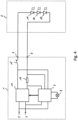
- Fig. 1 shows an emergency lighting system with an emergency converter 1 detachably connected to a LED lighting device 2 (emergency lighting means).
- the parts shown in Fig. 1 can be housed in an emergency luminaire.
- the emergency converter 1 comprises a light device terminal 3, 4 (connectors) for connecting the LED lighting device 2 to the emergency converter 1, mains terminal 5, 6 (connectors) for connecting the emergency converter 1 to the mains supply, a control circuit 7, a test switch 8 connected in parallel to the light device terminal 3, 4, an indicator light 9 and a LED driver 10 for generating a LED drive current, which is output via the light device terminal 3, 4 to the LED lighting device 2.
- the LED lighting device 3 fed with the LED light current emits light from one or more LEDs 11..13.
- the emergency lighting system comprises an energy storage device and a charger/discharger circuitry for the energy storage device (not shown).
- the control circuit 7 is advantageously a microcontroller circuit or a dedicated application specific integrated circuit (ASIC) and controls the charger/discharger circuitry and the LED driver 10.
- the emergency converter 1 is fed from mains supply in case of normal operations when mains supply is available. In case of a mains failure, malfunction or functional test, the emergency converter 1 is provided with electric energy from the energy storage device via the charger/discharger circuitry (not shown).
- the emergency lighting system can operate in the maintained lighting mode, in which the LED lighting device 2 is used for a conventional lighting as well as for the emergency lighting.
- the structure of the charger/discharger circuitry, the LED driver 10 and the LED lighting device 2 are not essential for understanding the invention and may be of any known structure used in conjunction with emergency converters 1 for emergency lighting applications.
- the charger/discharger circuitry must only be capable to adapt its settings or to operate based on a signal of the control circuit 8.
- the control circuit 7 is configured to perform a function test or an operation endurance test when the test switch 8 is actuated by a user, and to output a signal indicating the test result to the user via the indicator light 9.
- the indicator light 9 can be a bicolor indicator light, for example comprising a red-light emitting diode (LED) and a green LED, to indicate different results (fail/pass) or also different operational stati of the emergency converter.
- the test switch 8 can be implemented in different forms, for example as rocker switch, a toggle switch or preferably as a push button.
- the control circuit 7 is configured to measure the voltage across the light device terminal 3, 4 and/or the voltage at a resistor 14 to detect the current supplied to the LED lighting device 2.
- the measured voltage/current is typically used to adjust the output power of the LED driver 10 and/or to detect faults or malfunctions of the LED lighting device 2. If the LED driver 10 includes a flyback converter, voltage/current supplied to the LED lighting device 2 can be determined indirectly via an auxiliary winding.
- the function of determining the output voltage/current is used to detect the status of the test switch 8.
- the test switch 8 is connected in parallel to the light device terminal 3, 4 and is configured to short-circuit the output of the LED lighting device 2 when the test switch 8 is actuated.
- the control circuit 7 is configured to detect the applied short circuit by determining that the voltage at the light device terminal 3, 4 is collapsing, in particular falls below a predefined threshold value, and/or that the current supplied to the LED lighting device 2 exceeds a threshold or changes by a certain amount. Similarly, the control circuit 7 detects when the short circuit has ended due to opening/release of the test switch 8 and starts the function test.
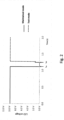
- Fig. 2 shows the voltage at the light device terminal 3, 4 detected by the control circuit 7, wherein the test switch 8 is actuated at time t on by the user and released at t off .
- approx. 10V is output at the light device terminal 3, 4 in the maintained lighting mode and the short circuit at time t on reduces the voltage to 0V, so that the LED lighting device 2 lights off, which causes feedback to the user.
- the reduction in voltage can cause the control circuit 7 to control the LED driver 10 to increase the voltage, but it remains low due to the short circuit.
- the short circuit is removed at time t off , the voltage increases abruptly. This is detected by the control circuit 7, which then switches from the maintained lighting mode into the test mode to perform the function test. After the function test has been performed or after a certain time, the control circuit 7 switches back to the maintained lighting mode (not shown).
- the function test can be prematurely terminated or interrupted if the test switch 8 is actuated during the function test.
- the control circuit 7 can control the LED driver 10 to generate a sensor voltage/current that is high enough to detect the short circuit and low enough to prevent the LED lighting device 2 from lighting up.
- Fig. 3 shows the voltage at the light device terminal 3, 4 of the emergency converter 1 operating in the non-maintained lighting mode, in which the emergency converter 1 generates slow, narrow voltage pulses to detect the short circuit.
- the short circuit at time t on reduces the voltage to 0V, which increases abruptly when the short circuit is removed at time t off . This is detected by the control circuit 7, which then switches from the non-maintained lighting mode into the test mode to perform the function test as described above.
- a short circuit is applied by actuating the test switch 8.
- a test switch that disconnects the LED lighting device 2 from the LED driver 10 can be used.
- Fig. 4 shows an emergency light system, in which the control circuit 7 determines an open circuit caused by actuating a test switch 15 (break contact).
- the test switch 15 disconnects the LED lighting device 2 from the LED driver 10 as long as it is actuated und the control circuit 7 detects this open circuit by determining that the current supplied to the LED lighting device 2 is collapsing, in particular falls below a predefined threshold value, and/or that the voltage at the light device terminal 3, 4 exceeds a threshold or changes by a certain amount and starts the function test when the open circuit has ended due to closing/release of the test switch 15.
- both test switches 8 and 15 may be used, with the function test being started when the user actuates the test switch 8 and the operational endurance test being started when the user actuates the test switch 15, or vice versa.
- Fig. 5 and Fig. 6 show an emergency light system according to a third and fourth embodiment of the present invention, respectively, in which the test switch 8 is connected to a terminal of the LED lighting device 2 or is a part the LED lighting device 2.
- the test switch 8 is connected to a terminal of the LED lighting device 2 or is a part the LED lighting device 2.
- all LEDs 11..13 and 16..21 are short-circuited when the user actuates the test switch 8, whereas only a part of LEDs 11..13 and 16..27 is short-circuited in Fig. 6 .
- the control circuit 7 detects the applied short circuit by determining that the voltage at the light device terminal 3, 4 is collapsing or falls below a predefined threshold value, and/or that the current supplied to the LED lighting device 2 exceeds a threshold or changes by a certain amount and starts the test when the short circuit has ended due to opening/release of the test switch 8.
- the resistors 28 and 28 shown in Fig. 6 provide a necessary voltage change required for the non-maintained mode.
- the function test or the operation duration test can be selected by actuating the respective test switch 8 or 15. Alternatively or in addition, different operation duration of the test switch 8, 15 can be assigned to the function and operation duration test. Since in Fig. 6 only a part (LEDs 22..27) of the LEDs is short-circuited by the test switch 8, the other part (LEDs 11..13 and 16..21) can be used to output information to the user while pressing the test switch 8. In particular, a flashing signal can be emitted by the other part as long as the user has to press the test switch 8, for example, to start the function test. The control circuit 7 has to filter out the flashing signal or consider it when detecting the status of the test switch 8. Alternatively or in addition, the information can be output via the indicator light 9.
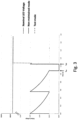
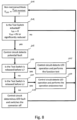
- Fig. 7 shows a flowchart of a method for controlling the emergency converter 1 shown in Fig. 1 in the maintained mode.
- the control circuit 7 sets nominal current I LED and voltage V LED and the LED driver 10 generates I LED supplied to the LED lighting device 2.
- the control circuit 7 determines whether the voltage V LED at the light device terminal 3, 4 is reduced to 0V to determine whether the user has actuated the test switch 8. If the test switch 8 is actuated, the control circuit 7 detects potential fault and starts a timer in step S3.
- step S4 the control circuit 7 determines whether the short circuit has been removed before the timer reaches time t 1 and performs the function test in step S 5 if the short circuit is removed before the timer reaches time t 1 .
- step S6 the control circuit 7 determines whether the short circuit has been removed before the timer reaches time t 2 , where t 2 > t 1 , and performs the operation endurance test in step S6 if the short circuit is removed before the timer reaches time t 2 . If the short circuit is not removed before timer reaches the time t 2 , the control circuit 7 determines a fault of the emergency converter 1 and switches the converter off in step S8. In addition, the control circuit 7 can restart the emergency converter 1 after a certain waiting time.
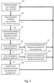
- Fig. 8 shows a flowchart of a method for controlling the emergency converter 1 shown in Fig. 1 in the non-maintained mode.
- the control circuit 7 sets the voltage V LED to about half of the nominal voltage V LED nominal (generally: o ⁇ V LED ⁇ V LED nominal ).
- the control circuit 7 determines whether the voltage V LED at the light device terminal 3, 4 is reduced to 0V to determine whether the user has actuated the test switch 8. If the test switch 8 is actuated, the control circuit 7 detects potential fault and starts a timer in step S13.
- step S14 the control circuit 7 determines whether the short circuit has been removed before the timer reaches time t 1 and performs the function test in step S 15 if the short circuit is removed before the timer reaches time t 1 .
- step S16 the control circuit 7 determines whether the short circuit has been removed before the timer reaches time t 2 , where t 2 > t 1 , and performs the operation endurance test in step S16 if the short circuit is removed before the timer reaches time t 2 . If the short circuit is not removed before timer reaches the time t 2 , the control circuit 7 determines a fault of the emergency converter 1 and switches the converter off in step S18. In addition, the control circuit 7 can restart the emergency converter 1 after a certain waiting time.
Landscapes
- Engineering & Computer Science (AREA)
- Power Engineering (AREA)
- Business, Economics & Management (AREA)
- Emergency Management (AREA)
- Circuit Arrangement For Electric Light Sources In General (AREA)
Priority Applications (2)
| Application Number | Priority Date | Filing Date | Title |
|---|---|---|---|
| EP22213000.7A EP4387045A1 (fr) | 2022-12-13 | 2022-12-13 | Convertisseur de secours avec fonction de test |
| PCT/EP2023/084266 WO2024126159A1 (fr) | 2022-12-13 | 2023-12-05 | Convertisseur d'urgence à fonction de test |
Applications Claiming Priority (1)
| Application Number | Priority Date | Filing Date | Title |
|---|---|---|---|
| EP22213000.7A EP4387045A1 (fr) | 2022-12-13 | 2022-12-13 | Convertisseur de secours avec fonction de test |
Publications (1)
| Publication Number | Publication Date |
|---|---|
| EP4387045A1 true EP4387045A1 (fr) | 2024-06-19 |
Family
ID=84519650
Family Applications (1)
| Application Number | Title | Priority Date | Filing Date |
|---|---|---|---|
| EP22213000.7A Pending EP4387045A1 (fr) | 2022-12-13 | 2022-12-13 | Convertisseur de secours avec fonction de test |
Country Status (2)
| Country | Link |
|---|---|
| EP (1) | EP4387045A1 (fr) |
| WO (1) | WO2024126159A1 (fr) |
Citations (3)
| Publication number | Priority date | Publication date | Assignee | Title |
|---|---|---|---|---|
| JPH04249020A (ja) * | 1991-02-04 | 1992-09-04 | Fuji Electric Co Ltd | 電磁接触器 |
| EP3755122A1 (fr) * | 2019-06-17 | 2020-12-23 | Tridonic GmbH & Co. KG | Commutateur de sélection de durée d'un convertisseur d'éclairage d'urgence |
| US20220205597A1 (en) * | 2012-06-15 | 2022-06-30 | Aleddra Inc. | Light-Emitting Diode Lamps With Battery Backup User Interfaces |
-
2022
- 2022-12-13 EP EP22213000.7A patent/EP4387045A1/fr active Pending
-
2023
- 2023-12-05 WO PCT/EP2023/084266 patent/WO2024126159A1/fr unknown
Patent Citations (3)
| Publication number | Priority date | Publication date | Assignee | Title |
|---|---|---|---|---|
| JPH04249020A (ja) * | 1991-02-04 | 1992-09-04 | Fuji Electric Co Ltd | 電磁接触器 |
| US20220205597A1 (en) * | 2012-06-15 | 2022-06-30 | Aleddra Inc. | Light-Emitting Diode Lamps With Battery Backup User Interfaces |
| EP3755122A1 (fr) * | 2019-06-17 | 2020-12-23 | Tridonic GmbH & Co. KG | Commutateur de sélection de durée d'un convertisseur d'éclairage d'urgence |
Also Published As
| Publication number | Publication date |
|---|---|
| WO2024126159A1 (fr) | 2024-06-20 |
Similar Documents
| Publication | Publication Date | Title |
|---|---|---|
| CA2766422C (fr) | Circuit electronique permettant de convertir un eclairage sur secteur en un eclairage de secours | |
| CN110024259B (zh) | 具有测试开关和状态指示器的操作装置 | |
| JP2015520481A (ja) | 照明装置 | |
| KR20140102268A (ko) | 쌍방향 부스터/충전기 회로를 포함하는 비상 조명 시스템 | |
| TWI488019B (zh) | 二線式負載控制裝置 | |
| EP3403310A1 (fr) | Unité d'éclairage de secours à charge électrique ca | |
| US5909181A (en) | Method and apparatus for indicating electrical connection | |
| CN110562811B (zh) | 安全回路状态检测装置及电梯系统 | |
| CN112147496B (zh) | 电子开关测试装置及方法 | |
| EP4387045A1 (fr) | Convertisseur de secours avec fonction de test | |
| US11729886B2 (en) | Duration select switch for an emergency lighting converter | |
| US11641130B2 (en) | Converter unit using a status lamp | |
| GB2541470A (en) | Controlled mains changeover in an emergency LED converter | |
| EP4401281A1 (fr) | Convertisseur de secours avec fonction d'économie d'énergie | |
| JPH0330279B2 (fr) | ||
| JPS5816157Y2 (ja) | 非常用蓄電池の寿命判別装置 | |
| JPH10262339A (ja) | 電池の保護装置 | |
| KR900002494Y1 (ko) | 테스터겸용 안전 콘센트 회로 | |
| JP2005183282A (ja) | 誘導灯 | |
| JP3254033B2 (ja) | 放電灯点灯装置 | |
| JPS6026275B2 (ja) | 非常灯用バツテリ−チエツカ− | |
| KR970077877A (ko) | 밧데리의 충전회로 | |
| JPH01177819A (ja) | 励磁監視ユニット | |
| JPH1126173A (ja) | 高圧放電ランプの点灯装置 | |
| JPS5820469B2 (ja) | 誘導灯などの点検表示装置 |
Legal Events
| Date | Code | Title | Description |
|---|---|---|---|
| PUAI | Public reference made under article 153(3) epc to a published international application that has entered the european phase |
Free format text: ORIGINAL CODE: 0009012 |
|
| STAA | Information on the status of an ep patent application or granted ep patent |
Free format text: STATUS: THE APPLICATION HAS BEEN PUBLISHED |
|
| AK | Designated contracting states |
Kind code of ref document: A1 Designated state(s): AL AT BE BG CH CY CZ DE DK EE ES FI FR GB GR HR HU IE IS IT LI LT LU LV MC ME MK MT NL NO PL PT RO RS SE SI SK SM TR |
|
| STAA | Information on the status of an ep patent application or granted ep patent |
Free format text: STATUS: REQUEST FOR EXAMINATION WAS MADE |
|
| 17P | Request for examination filed |
Effective date: 20240808 |
|
| RBV | Designated contracting states (corrected) |
Designated state(s): AL AT BE BG CH CY CZ DE DK EE ES FI FR GB GR HR HU IE IS IT LI LT LU LV MC ME MK MT NL NO PL PT RO RS SE SI SK SM TR |