EP4386491A1 - Verfahren zur reduzierung des stromverbrauchs einer wearable-vorrichtung und wearable-vorrichtung - Google Patents
Verfahren zur reduzierung des stromverbrauchs einer wearable-vorrichtung und wearable-vorrichtung Download PDFInfo
- Publication number
- EP4386491A1 EP4386491A1 EP22860486.4A EP22860486A EP4386491A1 EP 4386491 A1 EP4386491 A1 EP 4386491A1 EP 22860486 A EP22860486 A EP 22860486A EP 4386491 A1 EP4386491 A1 EP 4386491A1
- Authority
- EP
- European Patent Office
- Prior art keywords
- wearable device
- main body
- processor
- display screen
- faces upward
- Prior art date
- Legal status (The legal status is an assumption and is not a legal conclusion. Google has not performed a legal analysis and makes no representation as to the accuracy of the status listed.)
- Pending
Links
Images


Classifications
-
- G—PHYSICS
- G04—HOROLOGY
- G04G—ELECTRONIC TIME-PIECES
- G04G21/00—Input or output devices integrated in time-pieces
-
- G—PHYSICS
- G04—HOROLOGY
- G04G—ELECTRONIC TIME-PIECES
- G04G17/00—Structural details; Housings
-
- G—PHYSICS
- G04—HOROLOGY
- G04G—ELECTRONIC TIME-PIECES
- G04G17/00—Structural details; Housings
- G04G17/02—Component assemblies
- G04G17/04—Mounting of electronic components
- G04G17/045—Mounting of the display
-
- G—PHYSICS
- G04—HOROLOGY
- G04G—ELECTRONIC TIME-PIECES
- G04G17/00—Structural details; Housings
- G04G17/08—Housings
-
- G—PHYSICS
- G04—HOROLOGY
- G04G—ELECTRONIC TIME-PIECES
- G04G19/00—Electric power supply circuits specially adapted for use in electronic time-pieces
-
- G—PHYSICS
- G04—HOROLOGY
- G04G—ELECTRONIC TIME-PIECES
- G04G21/00—Input or output devices integrated in time-pieces
- G04G21/02—Detectors of external physical values, e.g. temperature
-
- G—PHYSICS
- G06—COMPUTING OR CALCULATING; COUNTING
- G06F—ELECTRIC DIGITAL DATA PROCESSING
- G06F1/00—Details not covered by groups G06F3/00 - G06F13/00 and G06F21/00
- G06F1/16—Constructional details or arrangements
- G06F1/1613—Constructional details or arrangements for portable computers
- G06F1/1615—Constructional details or arrangements for portable computers with several enclosures having relative motions, each enclosure supporting at least one I/O or computing function
- G06F1/1616—Constructional details or arrangements for portable computers with several enclosures having relative motions, each enclosure supporting at least one I/O or computing function with folding flat displays, e.g. laptop computers or notebooks having a clamshell configuration, with body parts pivoting to an open position around an axis parallel to the plane they define in closed position
- G06F1/162—Constructional details or arrangements for portable computers with several enclosures having relative motions, each enclosure supporting at least one I/O or computing function with folding flat displays, e.g. laptop computers or notebooks having a clamshell configuration, with body parts pivoting to an open position around an axis parallel to the plane they define in closed position changing, e.g. reversing, the face orientation of the screen with a two degrees of freedom mechanism, e.g. for folding into tablet PC like position or orienting towards the direction opposite to the user to show to a second user
-
- G—PHYSICS
- G06—COMPUTING OR CALCULATING; COUNTING
- G06F—ELECTRIC DIGITAL DATA PROCESSING
- G06F1/00—Details not covered by groups G06F3/00 - G06F13/00 and G06F21/00
- G06F1/16—Constructional details or arrangements
- G06F1/1613—Constructional details or arrangements for portable computers
- G06F1/163—Wearable computers, e.g. on a belt
-
- G—PHYSICS
- G06—COMPUTING OR CALCULATING; COUNTING
- G06F—ELECTRIC DIGITAL DATA PROCESSING
- G06F1/00—Details not covered by groups G06F3/00 - G06F13/00 and G06F21/00
- G06F1/16—Constructional details or arrangements
- G06F1/1613—Constructional details or arrangements for portable computers
- G06F1/1633—Constructional details or arrangements of portable computers not specific to the type of enclosures covered by groups G06F1/1615 - G06F1/1626
- G06F1/1637—Details related to the display arrangement, including those related to the mounting of the display in the housing
- G06F1/1647—Details related to the display arrangement, including those related to the mounting of the display in the housing including at least an additional display
-
- G—PHYSICS
- G06—COMPUTING OR CALCULATING; COUNTING
- G06F—ELECTRIC DIGITAL DATA PROCESSING
- G06F1/00—Details not covered by groups G06F3/00 - G06F13/00 and G06F21/00
- G06F1/16—Constructional details or arrangements
- G06F1/1613—Constructional details or arrangements for portable computers
- G06F1/1633—Constructional details or arrangements of portable computers not specific to the type of enclosures covered by groups G06F1/1615 - G06F1/1626
- G06F1/1675—Miscellaneous details related to the relative movement between the different enclosures or enclosure parts
- G06F1/1677—Miscellaneous details related to the relative movement between the different enclosures or enclosure parts for detecting open or closed state or particular intermediate positions assumed by movable parts of the enclosure, e.g. detection of display lid position with respect to main body in a laptop, detection of opening of the cover of battery compartment
-
- G—PHYSICS
- G06—COMPUTING OR CALCULATING; COUNTING
- G06F—ELECTRIC DIGITAL DATA PROCESSING
- G06F1/00—Details not covered by groups G06F3/00 - G06F13/00 and G06F21/00
- G06F1/16—Constructional details or arrangements
- G06F1/1613—Constructional details or arrangements for portable computers
- G06F1/1633—Constructional details or arrangements of portable computers not specific to the type of enclosures covered by groups G06F1/1615 - G06F1/1626
- G06F1/1675—Miscellaneous details related to the relative movement between the different enclosures or enclosure parts
- G06F1/1679—Miscellaneous details related to the relative movement between the different enclosures or enclosure parts for locking or maintaining the movable parts of the enclosure in a fixed position, e.g. latching mechanism at the edge of the display in a laptop or for the screen protective cover of a PDA
-
- G—PHYSICS
- G06—COMPUTING OR CALCULATING; COUNTING
- G06F—ELECTRIC DIGITAL DATA PROCESSING
- G06F1/00—Details not covered by groups G06F3/00 - G06F13/00 and G06F21/00
- G06F1/26—Power supply means, e.g. regulation thereof
- G06F1/32—Means for saving power
- G06F1/3203—Power management, i.e. event-based initiation of a power-saving mode
- G06F1/3234—Power saving characterised by the action undertaken
- G06F1/325—Power saving in peripheral device
- G06F1/3265—Power saving in display device
-
- G—PHYSICS
- G06—COMPUTING OR CALCULATING; COUNTING
- G06F—ELECTRIC DIGITAL DATA PROCESSING
- G06F1/00—Details not covered by groups G06F3/00 - G06F13/00 and G06F21/00
- G06F1/26—Power supply means, e.g. regulation thereof
- G06F1/32—Means for saving power
- G06F1/3203—Power management, i.e. event-based initiation of a power-saving mode
- G06F1/3234—Power saving characterised by the action undertaken
- G06F1/3287—Power saving characterised by the action undertaken by switching off individual functional units in the computer system
-
- G—PHYSICS
- G06—COMPUTING OR CALCULATING; COUNTING
- G06F—ELECTRIC DIGITAL DATA PROCESSING
- G06F1/00—Details not covered by groups G06F3/00 - G06F13/00 and G06F21/00
- G06F1/26—Power supply means, e.g. regulation thereof
- G06F1/32—Means for saving power
- G06F1/3203—Power management, i.e. event-based initiation of a power-saving mode
- G06F1/3234—Power saving characterised by the action undertaken
- G06F1/3293—Power saving characterised by the action undertaken by switching to a less power-consuming processor, e.g. sub-CPU
-
- H—ELECTRICITY
- H04—ELECTRIC COMMUNICATION TECHNIQUE
- H04M—TELEPHONIC COMMUNICATION
- H04M1/00—Substation equipment, e.g. for use by subscribers
- H04M1/72—Mobile telephones; Cordless telephones, i.e. devices for establishing wireless links to base stations without route selection
- H04M1/724—User interfaces specially adapted for cordless or mobile telephones
- H04M1/72448—User interfaces specially adapted for cordless or mobile telephones with means for adapting the functionality of the device according to specific conditions
- H04M1/72454—User interfaces specially adapted for cordless or mobile telephones with means for adapting the functionality of the device according to specific conditions according to context-related or environment-related conditions
-
- H—ELECTRICITY
- H04—ELECTRIC COMMUNICATION TECHNIQUE
- H04M—TELEPHONIC COMMUNICATION
- H04M1/00—Substation equipment, e.g. for use by subscribers
- H04M1/72—Mobile telephones; Cordless telephones, i.e. devices for establishing wireless links to base stations without route selection
- H04M1/724—User interfaces specially adapted for cordless or mobile telephones
- H04M1/72448—User interfaces specially adapted for cordless or mobile telephones with means for adapting the functionality of the device according to specific conditions
- H04M1/72463—User interfaces specially adapted for cordless or mobile telephones with means for adapting the functionality of the device according to specific conditions to restrict the functionality of the device
-
- Y—GENERAL TAGGING OF NEW TECHNOLOGICAL DEVELOPMENTS; GENERAL TAGGING OF CROSS-SECTIONAL TECHNOLOGIES SPANNING OVER SEVERAL SECTIONS OF THE IPC; TECHNICAL SUBJECTS COVERED BY FORMER USPC CROSS-REFERENCE ART COLLECTIONS [XRACs] AND DIGESTS
- Y02—TECHNOLOGIES OR APPLICATIONS FOR MITIGATION OR ADAPTATION AGAINST CLIMATE CHANGE
- Y02D—CLIMATE CHANGE MITIGATION TECHNOLOGIES IN INFORMATION AND COMMUNICATION TECHNOLOGIES [ICT], I.E. INFORMATION AND COMMUNICATION TECHNOLOGIES AIMING AT THE REDUCTION OF THEIR OWN ENERGY USE
- Y02D30/00—Reducing energy consumption in communication networks
- Y02D30/70—Reducing energy consumption in communication networks in wireless communication networks
Definitions
- This application relates to the field of wearable devices, and in particular, to a method for reducing power consumption of a wearable device and a wearable device.
- Wearable devices such as smartwatches are favored by users due to portability and rich functions (such as workout monitoring, intelligent positioning, and voice call) of the wearable devices.
- portability such as workout monitoring, intelligent positioning, and voice call
- watch bodies of the smartwatches are limited in size, power of the smartwatches is often insufficient. How to reduce power consumption of smartwatches has become a research hotspot for device manufacturers.
- This application provides a method for reducing power consumption of a wearable device and a wearable device. Power consumption of the wearable device can be reduced based on a use requirement of a user, and standby duration of the wearable device can be prolonged.
- a method for reducing power consumption of a wearable device is provided.
- the method is applied to the wearable device.
- the wearable device includes a main body and a bottom support configured to support the main body, and the main body is rotatable relative to the bottom support.
- a first display screen is disposed on a front surface of the main body.
- a second display screen is disposed on a back surface of the main body. Power consumption caused when the first display screen displays an image is greater than power consumption caused when the second display screen displays an image.
- the method includes: detecting whether the front surface or the back surface of the main body of the wearable device faces upward. When a detection result is that the front surface of the main body of the wearable device faces upward, the wearable device controls the first display screen to display an image. When the detection result is that the back surface of the main body of the wearable device faces upward, the wearable device turns off the first display screen, and controls the second display screen to display an image.
- a watch body of the wearable device may be turned over, so that the back surface of the watch body faces upward (or the front surface faces downward), to control the smartwatch to enter a preset mode with low power consumption.
- the wearable device may turn off the first display screen with high power consumption, and turn on the second display screen with low power consumption, to reduce the power consumption of the wearable device and prolong standby duration of the wearable device.
- the second display screen may be an LCD, for example, a TN-type LCD, an HTN-type LCD, an STN-type LCD, or an FSTN-type LCD.
- the second display screen may be a segment display screen.
- a fixed position in the segment display screen has pixels, and only simple images, such as numbers, texts, and symbols, can be displayed at the fixed position.
- the second display screen may be a dot matrix screen. There are pixels arranged in an array in the dot matrix screen, and rich images may be displayed at any position.
- the dot matrix screen may have a small quantity of pixels. For example, the pixels may be less than or equal to 200.
- the method further includes: When the detection result is that the back surface of the main body of the wearable device faces upward, the wearable device further disables one or more of the following functions: a sound function, a push function, and a network heartbeat function.
- the wearable device may further disable some unimportant functions, to further reduce the power consumption of the wearable device.
- the method further includes: When the detection result is that the back surface of the main body of the wearable device faces upward, the wearable device further disables one or more of the following functions: a positioning function, a call function, and a pedometer function.
- the wearable device may further disable some important functions with high power consumption, to minimize the power consumption of the wearable device and ensure that the wearable device can be used at more critical moments in the future.
- the wearable device includes a first processor and a second processor.
- the first processor is configured to control the first display screen
- the second processor is configured to control the second display screen. That the wearable device controls the first display screen to display an image when a detection result is that the front surface of the main body of the wearable device faces upward includes: When the detection result is that the front surface of the main body of the wearable device faces upward, the first processor controls the first display screen to display the image, and the second processor controls the second display screen not to display an image.
- That the wearable device turns off the first display screen, and controls the second display screen to display an image when the detection result is that the back surface of the main body of the wearable device faces upward includes: When the detection result is that the back surface of the main body of the wearable device faces upward, the first processor controls the first display screen not to display an image, and the second processor controls the second display screen to display the image.
- power consumption caused when the first processor controls the first display screen to display an image is greater than power consumption caused when the second processor controls the second display screen to display an image.
- that the first processor controls the first display screen to display the image, and the second processor controls the second display screen not to display an image when the detection result is that the front surface of the main body of the wearable device faces upward is specifically: When the detection result is that the front surface of the main body of the wearable device faces upward, the first processor controls the first display screen to display the image, and the second processor is in a disabled state or a sleep state.
- That the first processor controls the first display screen not to display an image, and the second processor controls the second display screen to display the image when the detection result is that the back surface of the main body of the wearable device faces upward is specifically:
- the first processor turns off the first display screen and wakes up the second processor, and the second processor controls the second display screen to display the image.
- the second processor when the first processor controls the first display screen to display the image, the second processor may not be enabled or may be disabled.
- the first processor enables or wakes up the second processor, so that the second processor controls the second display screen to display the image, to reduce the power consumption of the wearable device.
- a Hall effect sensor is disposed on the main body, a magnetic body is disposed on the bottom support, and the Hall effect sensor detects a magnetic field generated by the magnetic body.
- the wearable device determines, based on a detection signal of the Hall effect sensor, whether the front surface or the back surface of the main body of the wearable device faces upward.
- an embodiment of this application provides a method for detecting whether a front surface or a back surface of a main body of a wearable device faces upward.
- a distance between the Hall effect sensor and the magnetic body when the front surface of the main body of the wearable device faces upward is different from a distance between the Hall effect sensor and the magnetic body when the back surface of the main body faces upward.
- the first processor of the wearable device determines that the front surface of the main body of the wearable device faces upward.
- the first processor of the wearable device determines that the back surface of the main body of the wearable device faces upward. The second distance value is different from the first distance value.
- the first distance value is a numerical value or a range of numerical values.
- the second distance value is a numerical value or a range of numerical values. It may be understood that, due to different strengths of turning-over actions of the user, or slight shaking of an arm of the user, the Hall effect sensor may detect a slight change in a distance between the main body 11 and the bottom support 13 when the front surface of the main body of the wearable device faces upward or the back surface of the main body faces upward. In other words, the first distance value and the second distance value may change within a small numerical range.
- the Hall effect sensor may be specifically a single-axis Hall effect sensor, or may be a three-axis Hall effect sensor.
- the single-axis Hall effect sensor has low costs, and can reduce the power consumption of the wearable device while reducing costs as much as possible.
- the method further includes: When the first processor of the wearable device determines that the front surface of the main body of the wearable device faces upward, the first processor of the wearable device notifies the second processor to turn off the second display screen. The first processor of the wearable device controls the first display screen to display an image.
- the method further includes: After the first processor of the wearable device turns off the first display screen and wakes up the second processor, the first processor enters a sleep state or a disabled state.
- the first processor may enter the sleep state or the disabled state, to further reduce the power consumption of the wearable device.
- the second processor is electrically connected to the Hall effect sensor of the main body. After the wearable device turns off the first display screen, and controls the second display screen to display the image when the detection result is that the back surface of the main body of the wearable device faces upward, the method further includes: The second processor of the wearable device determines, based on the detection signal of the Hall effect sensor, that the front surface of the main body of the wearable device faces upward. The second processor of the wearable device turns off the second display screen, and wakes up the first processor of the wearable device. The first processor of the wearable device controls the first display screen to display an image.
- the user may further perform a reverse operation, that is, turn over the watch body of the wearable device, so that the front surface of the watch body faces upward, the wearable device is controlled to return to a normal mode, and the first display screen is enabled to redisplay the image.
- that the second processor of the wearable device determines, based on the detection signal of the Hall effect sensor, that the front surface of the main body of the wearable device faces upward includes: When determining, based on the detection signal of the Hall effect sensor, that the distance between the main body and the bottom support is the first distance value, the second processor of the wearable device determines that the front surface of the main body of the wearable device faces upward.
- the method further includes: When the first processor of the wearable device determines, based on the detection signal of the Hall effect sensor, that the main body of the wearable device is separated from the bottom support, and the wearable device receives an incoming call, the wearable device automatically answers the incoming call.
- the smartwatch when the smartwatch receives the incoming call, the most likely reason for the user to remove the watch body of the smartwatch is to facilitate placing the watch body by the user next to an ear to answer the call. Therefore, the smartwatch can automatically answer the incoming call, meeting an operation intention of the user.
- the smartwatch when the smartwatch receives the incoming call, the user may remove the watch body from the bottom support, and then directly place the watch body next to the ear to answer the call.
- the answering method provided in embodiments of this application provides better operation experience.
- the wearable device when the first processor of the wearable device determines, based on the detection signal of the Hall effect sensor, that the main body of the wearable device is separated from the bottom support, and the wearable device does not perform the call function, the wearable device automatically starts a camera application or displays a shortcut menu.
- the shortcut menu includes one or more of an option for starting a contact list, an option for starting the camera application, and/or a function option for searching for a surrounding device.
- that the first processor of the wearable device determines, based on the detection signal of the Hall effect sensor, that the main body of the wearable device is separated from the bottom support includes: When the first processor of the wearable device determines, based on the detection signal of the Hall effect sensor, that the distance between the main body and the bottom support is greater than or equal to a third distance value, the first processor of the wearable device determines that the main body of the wearable device is separated from the bottom support.
- the third distance value is greater than the first distance value, and the third distance value is greater than the second distance value.
- an embodiment of this application provides a method for detecting an action of removing a main body of a wearable device from a bottom support by a user, that is, detecting a state in which the main body of the wearable device is separated from the bottom support.
- a wearable device including a main body and a bottom support configured to support the main body.
- the main body is rotatable relative to the bottom support.
- a first display screen is disposed on a front surface of the main body.
- a second display screen is disposed on a back surface of the main body. Power consumption caused when the first display screen displays an image is greater than power consumption caused when the second display screen displays an image.
- the main body further includes a memory, a first processor, and a second processor.
- the memory is configured to store computer program code.
- the computer program code includes computer instructions.
- a computer-readable storage medium including computer instructions.
- the wearable device is enabled to perform the method according to any one of the first aspect or the possible implementations of the first aspect.
- a computer program product is provided.
- the wearable device is enabled to perform the method according to any one of the first aspect or the possible implementations of the first aspect.
- a chip system including one or more processors.
- the one or more processors execute instructions, the one or more processors perform the method according to any one of the first aspect or the possible implementations of the first aspect.
- A/B may represent A or B.
- the terms such as “example” or “for example” are used to indicate examples, illustrations, or descriptions. Any embodiment or design scheme described as an “example” or “for example” in embodiments of this application should not be explained as being more preferred or having more advantages than another embodiment or design scheme. Exactly, use of the terms such as “example” or “for example” is intended to present a related concept in a specific manner.
- a wearable device such as a smartwatch
- a first method For a kids watch, a parent may disable, on a parent application (application, APP) end, functions with high power consumption, such as a trajectory function, of the kids watch, thereby reducing power consumption of the kids watch.
- a parent application application, APP
- functions with high power consumption such as a trajectory function
- the parent cannot know an actual usage of power of the kids watch. Therefore, the parent cannot disable the functions such as the trajectory function of the kids watch in time when battery power is low, and cannot reduce the power consumption of the kids watch in time.
- a second method The wearable device such as the smartwatch may also automatically enter a low power consumption mode when detecting that power of the wearable device is lower than a preset value (for example, 20%), and disable functions with high power consumption such as a positioning function.
- a preset value for example, 20%
- the method helps reduce the power consumption of the smartwatch when the power is insufficient, a use requirement of a user when the battery power is insufficient cannot be met.
- the kids watch is still used as an example. During school classes, a student spends less time using the kids watch, but the kids watch has sufficient power, is in a normal working state, and continuously performs positioning, and the like.
- the parent needs to know the student's trajectory through the positioning of the kids watch, but the kids watch may not have sufficient power and has automatically entered a low power consumption mode, in which the positioning function is disabled. It can be learned that, determining to enter the low power consumption mode only based on the power of the kids watch does not meet the use requirement of the user.
- an embodiment of this application provides a method for reducing power consumption of a wearable device.
- the method is applied to a wearable device including a rotating apparatus.
- the rotating apparatus can implement a rotation of a main body of the wearable device relative to a bottom support of the wearable device.
- the main body of the wearable device is a functional main body of the wearable device.
- the main body may include a housing and a display screen mounted on the housing.
- the main body may further include other components, such as a main board, a battery, a camera module, a receiver, a speaker that are mounted in the housing.
- the bottom support can be used as a main body bearer.
- a structure of the bottom support of the wearable device may be designed based on a requirement, for example, a roughly square plateshaped structure. Two opposite ends of the bottom support can be used to connect a wristband. When the wristband is bound to a wrist, the bottom support can be in contact with skin.
- the wearable device described in embodiments of this application includes but is not limited to a smartwatch (for example, a kids watch) and a smart band.
- a smartwatch for example, a kids watch
- a smart band for example, a smart band
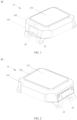
- a smartwatch 10 provided in this embodiment of this application may include a main body (also referred to as a watch body) 11, a latch component 14, a rotating apparatus 12, a bottom support 13, and a fixing snap member 15.
- the main body 11 is rotatable relative to the bottom support 13.
- the main body 11 may be a functional main body of the smartwatch 10, and may include a housing 113 and a display screen 111 (which may be referred to as a primary screen) mounted on the housing 113.
- the main body 11 may further include other components, such as a main board, a battery, a camera module, a receiver, a speaker that are mounted in the housing 113.
- There may be at least one camera module.
- a camera module 112 may be disposed on a front side of the housing 113 in FIG. 1 and FIG. 2 (a side on which the display screen 111 is mounted).
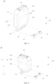
- a camera module 114 may be disposed on a back side of the housing 113 in FIG.
- the camera module may also be located on a side of the housing 113 (a surface in a direction around the display screen 111). Alternatively, the camera module may not be disposed.
- FIG. 1 and FIG. 2 show a state in which the main body 11 is placed horizontally on the bottom support 13, and the display screen 111 is in contact with the bottom support 13. In this case, a front surface of the main body/watch body of the smartwatch 10 faces upward.
- FIG. 3 shows a state in which the main body 11 is turned up relative to the bottom support 13.
- a display screen 115 (which may be referred to as a secondary screen) may further be disposed on the back side of the housing 113. Power consumption of the display screen 115 in a working state is lower than power consumption of the foregoing display screen 111 in the working state.
- the back side of the housing 113 may further include a solar panel 116.
- the solar panel 116 is configured to receive sunlight passing through a back side part of the housing 113, and convert solar radiation energy into electric energy.
- the electric energy converted by the solar panel 116 may be used as a backup to be used by the smartwatch 10 in an emergency situation. For example, when battery power of the smartwatch 10 is insufficient, the electric energy converted by the solar panel 116 may be used to implement functions such as calling for help in an emergency and swiping an access card.
- the display screen 115 may be controlled to work through hardware design and software design.
- a magnetic body may be mounted on the bottom support 13.
- a controller and a Hall effect sensor may be disposed in the housing 113.
- the controller may be a processor or any other device/component having a signal processing function.
- the controller is electrically connected to the Hall effect sensor, and is also electrically connected to the display screen 115.
- the Hall effect sensor is used with the magnetic body.
- the detection signal may be used by the controller to detect a current position of the display screen 115.
- the controller determines the current position of the display screen 115 based on the detection signal output by the Hall effect sensor, and controls the display screen 115 to work. For example, refer to FIG. 3 .
- the controller may control the display screen 115 to display simple images, such as numbers, texts, or symbols.
- the controller may control the display screen 115 to be in standby without displaying the images.
- the latch component 14 can be fixed to the main body 11, and the fixing snap member 15 can be fixed to the bottom support 13. Positions of the latch component 14 and the fixing snap member 15 relative to the bottom support 13 shown in the figures are merely examples. Actually, the latch component 14 and the fixing snap member 15 may be located on any side of the bottom support 13. When the main body 11 is placed horizontally on the bottom support 13, the main body 11 may be locked on the bottom support 13 through snap-fit between the latch component 14 and the fixing snap member 15. The user may press the latch component 14 to separate it from the fixing snap member 15 to release locking between the main body 11 and the bottom support 13.
- the main body 11 is rotatably connected to the bottom support 13 through the rotating apparatus 12.
- the position of the rotating apparatus 12 relative to the bottom support 13 shown in the figures is merely an example. Actually, the rotating apparatus 12 may be located on any side of the bottom support 13. After the main body 11 and the bottom support 13 are unlocked, the user can turn over the main body 11, so that the main body 11 rotates around an H axis and a V axis relative to the bottom support 13.
- the H axis is orthogonal to the V axis.
- the H axis When the smartwatch 10 is placed on a horizontal plane and the display screen 111 is parallel to the horizontal plane, the H axis may be substantially parallel to the horizontal plane, and the V axis may be substantially perpendicular to the horizontal plane. Therefore, the H axis may be referred to as a horizontal axis, and the V axis may be referred to as a vertical axis.
- the user can turn up the main body 11, rotate the main body 11 around the V axis by 180 degrees, and then lock the main body 11 to the bottom support 13, so that the front side of the housing 113 (the side on which the display screen 111 is mounted) is in contact with the bottom support 13.
- the back surface of the main body/watch body of the smartwatch 10 faces upward (or in other words, the front surface of the main body/watch body faces downward).
- the main body 11 may be locked on the bottom support 13 through snap-fit between the latch component 14 and the fixing snap member 15.
- the distance between the Hall effect sensor (for example, a single-axis Hall effect sensor or a three-axis Hall effect sensor) disposed in the main body 11 and the magnetic body of the bottom support is different that when the front surface of the main body 11 faces upward.
- the smartwatch 10 it may be identified, based on the detection signal output by the Hall effect sensor, that the smartwatch 10 is in a state in which the back surface of the main body faces upward, or in a state in which the front surface of the main body faces upward.
- the smartwatch 10 determines the detected distance between the Hall effect sensor disposed in the main body 11 and the magnetic body in the bottom support 13 as a distance between the main body 11 and the bottom support 13 of the smartwatch. For example, when it is determined, based on the detection signal of the Hall effect sensor, that the distance between the main body 11 and the bottom support 13 of the smartwatch is a preset distance value 1, it is determined that the smartwatch is in the state in which the back surface of the main body faces upward.
- the preset distance value 1 may be a numerical value or may be a range of numerical values.
- the Hall effect sensor may detect a slight change in the distance between the main body 11 and the bottom support 13.
- the preset distance value 1 may change within a small numerical range.
- a distance between the three-axis Hall effect sensor disposed in the main body 11 and the magnetic body of the bottom support may be the same as that when the front surface of the main body 11 faces upward.
- orientations of the three-axis Hall effect sensor relative to the magnetic body are different. For example, when the main body 11 of the smartwatch 10 is placed horizontally on the bottom support, and the bottom support is parallel to the horizontal plane, there is a distance difference in a horizontal direction between a position of the three-axis Hall effect sensor and a position of the magnetic body.
- the three-axis Hall effect sensor can detect a strength of magnetic field in the three-axis direction, when the back surface of the main body 11 of the smartwatch 10 face upward or when the front surface faces upward, at least a difference in the magnetic field on an axis can be detected by the three-axis Hall effect sensor. In other words, based on the detection signal output by the three-axis Hall effect sensor, it may be identified that the smartwatch 10 is in the state in which the back surface of the main body faces upward, or in the state in which the front surface of the main body faces upward.
- two or more magnetic bodies may be disposed on the bottom support of the smartwatch 10.
- the Hall effect sensor for example, the single-axis Hall effect sensor, or the three-axis Hall effect sensor
- the Hall effect sensor disposed in the main body of the smartphone 10 can detect a vector generated by the two or more magnetic bodies.
- the Hall effect sensor and the magnetic body are disposed, only that when the back surface of the main body 11 of the smartwatch 10 faces upward, the vector detected by the Hall effect sensor provided in the main body 11 is different from that when the front surface of the main body 11 faces upward needs to be ensured.
- the three-axis Hall effect sensor it may be identified that the smartwatch 10 is in the state in which the back surface of the main body faces upward, or in the state in which the front surface of the main body faces upward.
- neither a type and an arrangement position of the Hall effect sensor in the smartwatch 10, nor a quantity, an arrangement position, and the like of the magnetic body in the smartwatch 10 are specifically limited. Further, in embodiments of this application, a method for determining, by the smartwatch 10 based on the detection signal of the Hall effect sensor, whether the back surface of the main body 11 of the smartwatch 10 faces upward or the front surface faces upward is not limited.
- the rotating apparatus 12 not only enables the main body 11 of the smartwatch 10 to rotate relative to the bottom support 13, but also enables the main body 11 to be detachable from the bottom support 13.
- the distance between the Hall effect sensor in the housing 113 and the magnetic body on the bottom support 13 is much greater than that when the main body 11 is connected to the bottom support 13.
- a preset distance value 3 is greater than the foregoing preset distance value 1, and is greater than the foregoing preset distance value 2.
- FIG. 5 is a schematic diagram of another structure of the smartwatch 10.
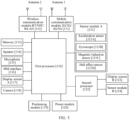
- the smartwatch 10 may include a first processor 130, a mobile communication module 131, a wireless communication module 132, a memory 133, a speaker 134, a microphone 135, a subscriber identification module (subscriber identification module, SIM) card interface 136, a display screen A117, a camera 118, a positioning module 119, a power module 120, and sensor module A121.
- the smartwatch 10 may further include a second processor 122, a display screen B 123, a sensor module B 124, and the like.
- the structure shown in this embodiment of the present invention does not constitute a specific limitation on the smartwatch 10.
- the smartwatch 10 may include more or fewer components than those shown in the figure, or some components may be combined, or some components may be divided, or different component arrangements may be used.
- the components shown in the figure may be implemented by hardware, software, or a combination of software and hardware.
- an interface connection relationship between the modules shown in embodiments of the present invention is merely a schematic description, and does not constitute a structural limitation on the smartwatch 10.
- the first processor 130 includes one or more processing units.
- the first processor 130 may include an application processor (application processor, AP), a modem processor, a graphics processing unit (graphics processing unit, GPU), an image signal processor (image signal processor, ISP), a controller, a video codec, and a digital signal processor (digital signal processor, DSP), a baseband processor, and/or a neural network processing unit (neural network processing unit, NPU), or the like.
- Different processing units may be independent devices, or may be integrated into one or more processors.
- a wireless communication function of the smartwatch 10 may be implemented by using an antenna 1, an antenna 2, the mobile communication module 131, the wireless communication module 132, the modem processor, the baseband processor, and the like.
- the display screen A117 is configured to display an image, a video, and the like.
- the display screen A117 includes a display panel.
- the display panel may be a liquid crystal display (liquid crystal display, LCD), an organic light-emitting diode (organic light-emitting diode, OLED), an active-matrix organic light-emitting diode (active-matrix organic light-emitting diode, AMOLED), a flex light-emitting diode (flex light-emitting diode, FLED), a mini-LED, a micro-LED, a micro-OLED, a quantum dot light-emitting diode (quantum dot light-emitting diode, QLED), or the like.
- the smartwatch 10 may include one or N display screens A117, where N is a positive integer greater than 1.
- the display screen A117 is disposed on a front surface of the smartwatch 10.
- the display screen A117 is also referred to as a "primary screen” or a "first display screen".
- the display screen A117 is the foregoing display screen 111 in FIG. 1 and FIG. 2 .
- the memory 133 may be configured to store computer executable program code, and the executable program code includes instructions.
- the memory 133 may include a program storage area and a data storage area.
- the program storage area may store an operating system, an application required by at least one function (such as a sound play function or an image play function), and the like.
- the data storage area may store data (such as audio data and image data) created in a process of using the smartwatch 10.
- the memory 133 may include a highspeed random access memory, and may further include a non-volatile memory, for example, at least one magnetic disk storage device, a flash memory, or a universal flash storage (universal flash storage, UFS).
- the first processor 130 executes various function applications and data processing of the smartwatch 10 by running the instructions stored in the memory 133 and/or instructions stored in the memory disposed in the processor.
- the speaker 134 also referred to as a "loudspeaker" is configured to convert an audio electrical signal into a sound signal.
- the smartwatch 10 may allow for listening to music or listening to a hands-free call through the speaker 134.
- the microphone 135, also referred to as a "mike” or a “mic”, is configured to convert the sound signal into an electrical signal.
- a user may make a sound through a human mouth close to the microphone 135, and input a sound signal to the microphone 135.
- the SIM card interface 136 is configured to connect to a SIM card.
- the SIM card may be inserted into the SIM card interface 136, or removed from the SIM card interface 136, to implement contact with and separation from the smartwatch 10.
- the SIM card interface 136 may support a nano-SIM card, a micro-SIM card, the SIM card, and the like.
- a plurality of cards may be inserted into the same SIM card interface 136 simultaneously. Types of the plurality of cards may be the same or different.
- the SIM card interface 136 may also be compatible with different types of SIM cards.
- the SIM card interface 136 may also be compatible with an external memory card.
- the smartwatch 10 interacts with a network through the SIM card, to implement functions such as call and data communication.
- the smartwatch 10 uses an eSIM, that is, an embedded SIM card.
- the eSIM card may be embedded in the smartwatch 10, and cannot be separated from the smartwatch 10.
- the sensor module A121 includes an acceleration sensor 121A, a gyroscope 121B, a magnetic induction sensor 121C, a Hall effect sensor 121D, and the like.
- the acceleration sensor 121A may detect accelerations of the smartwatch 10 in all directions (generally three axes). When the smartwatch 10 is stationary, magnitude and a direction of gravity may be detected.
- the gyroscope 121B may be configured to determine a motion attitude of the smartwatch 10. In some embodiments, angular velocities of the smartwatch 10 around three axes (that is, an x axis, a y axis, and a z axis) may be determined by using the gyroscope 121B.
- the magnetic induction sensor 121C also referred to as an electronic compass, is configured to position a device. In some examples, the smartwatch 10 may calculate an attitude of the smartwatch 10 based on the acceleration sensor 121A, the gyroscope 121B, and the magnetic induction sensor 121C, and apply the attitude to a pedometer application.
- the Hall effect sensor 121D is configured to detect whether a front surface or a back surface of a watch body of the smartwatch 10 faces upward, so that the first processor 130 determines whether the smartwatch 10 enters a do-not-disturb mode, a power saving mode, a predefined mode, or the like.
- the Hall effect sensor 121D is further configured to detect whether the watch body of the smartwatch 10 is separated from the housing, so that the first processor 130 determines whether to automatically answer calls or the like.
- the sensor module A121 may further include other sensors, and details are not described herein again.
- the second processor 122 is a microcontroller unit (microcontroller unit, MCU), also referred to as a single chip microcomputer (single chip microcomputer) or a single chip, and is configured to control devices such as the display screen B 123 and the sensor module B124.
- MCU microcontroller unit
- MCU single chip microcomputer
- single chip microcomputer single chip microcomputer
- the display screen B 123 is disposed on the back surface of the smartwatch 10.
- the display screen B123 is also referred to as a "secondary screen” or a "second display screen".
- the display screen B 123 is the foregoing display screen 115 in FIG. 3 and FIG. 4 .
- the display screen B123 may be an LCD, for example, a TN-type LCD, an HTN-type LCD, an STN-type LCD, or an FSTN-type LCD.
- the display screen B 123 may be a segment display screen. A fixed position in the segment display screen has pixels, and only simple images, such as numbers, texts, and symbols, can be displayed at the fixed position.
- the display screen B123 may be a dot matrix screen. There are pixels arranged in an array in the dot matrix screen, and rich images may be displayed at any position.
- the dot matrix screen may have a small quantity of pixels. For example, the pixels may be less than or equal to 200. Using the foregoing two types of display screens can reduce power usage during display of the smartwatch, thereby reducing power consumption. In other embodiments, a quantity of pixels of the dot matrix screen may not be limited.
- the transparent display screen is not limited to the segment screen or the dot matrix screen.
- the smartwatch 10 may further include the sensor module B 124.
- the sensor module B 124 may include an acceleration sensor, a gyroscope magnetometer, a barometer, a light sensor, an ultraviolet UV sensor, a Hall effect sensor, and the like. Certainly, the sensor module B 124 may further include other sensors, and details are not described herein again.
- a user may set accessibility features of a smartwatch by using a settings application of the smartwatch.
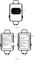
- section (1) in FIG. 6 is a home screen 601 of a settings application displayed by a smartwatch.
- the smartwatch displays an accessibility feature interface 602 shown in section (2) in FIG. 6 .
- the accessibility feature interface 602 includes a "back surface of watch body faces upward” option and a "watch body is removed” option.
- the accessibility feature interface 602 may further include an option for another function.
- the smartwatch displays a setting interface 603 with the "back surface of watch body faces upward” option shown in section (3) in FIG. 6 .
- the smartwatch automatically enters the do-not-disturb mode after detecting that the back surface of the watch body faces upward.
- the smartwatch turns off a primary screen (to be specific, the primary screen is controlled to not display an image, and the primary screen is in an off state), wakes up a second processor (for example, an MCU) to light up a secondary screen (to be specific, the second processor controls the secondary screen to display the image, and the secondary screen is in a working state).
- a primary screen to be specific, the primary screen is controlled to not display an image, and the primary screen is in an off state
- a second processor for example, an MCU
- power consumption caused when the smartwatch controls the secondary screen to be in the working state is lower than power consumption caused when the smartwatch controls the primary screen to be in the working state.
- the smartwatch after the smartwatch enters the do-not-disturb mode, overall power consumption of the smartwatch is reduced.
- the smartwatch after the smartwatch enters the do-not-disturb mode, the smartwatch further mutes a sound (for example, disables a voice prompt), and disables a push (push) function of the smartwatch (for example, does not push new information or an incoming call notification).
- the smartwatch may further disable a positioning function or the like. It should be noted that functions that are disabled after the smartwatch enters the do-not-disturb mode are not specifically limited in embodiments of this application.
- the smartwatch automatically enters the power saving mode after detecting that the back surface of the watch body faces upward.
- the smartwatch wakes up the second processor (for example, the MCU) to light up the secondary screen (to be specific, the secondary screen is controlled to display the image, and the secondary screen is in the working state).
- the smartwatch turns off the primary screen (to be specific, the primary screen is controlled to not display the image, and the primary screen is in the off state).
- the first processor of the smartwatch disables functions with high power consumption in the smartwatch, for example, the push function, the positioning function, or the call function of the smartwatch. It can be learned that, after the smartwatch enters the power saving mode, the overall power consumption of the smartwatch is reduced.
- the smartwatch may further disable the first processor (for example, an AP), thereby further reducing power consumption of the smartwatch.
- the smartwatch may receive a user-defined mode.
- the smartwatch automatically enters the user-defined mode after detecting that the back surface of the watch body faces upward.
- the user may customize, based on a use requirement of the user, functions that the smartwatch disables when the back surface of the smartwatch body faces upward, and the like. This is described in detail below.
- the user may not need to set the foregoing options.
- the smartwatch After detecting that the back surface of the watch body faces upward, the smartwatch automatically enters a default mode.
- the default mode may be any one of the foregoing modes.
- FIG. 7 is a schematic flowchart of a method for reducing power consumption of a wearable device (such as a smartwatch) according to an embodiment of this application. The process includes the following steps.
- S701 The smartwatch detects that the smartwatch is in a state in which a back surface of a watch body faces upward.
- the smartwatch enables a Hall effect sensor in the watch body, and the Hall effect sensor works with a magnetic body (for example, a magnet) disposed on a bottom support to detect a distance between the watch body and the bottom support of the smartwatch.
- the smartwatch keeps enabling the Hall effect sensor by default.
- the smartwatch In response to detecting that the smartwatch is in the state in which the back surface of the watch body faces upward, the smartwatch enters a preset mode.
- the preset mode includes any one of the following modes: a do-not-disturb mode, a power saving mode, and a user-defined mode.
- Table 1 shows comparison of working states and running functions of devices in the smartwatch in the preset mode and a normal mode.
- the normal mode refers to a working mode of the smartwatch when a front surface of the watch body faces upward, or a working mode of the smartwatch when the front surface of the watch body faces upward and power is sufficient.
- the smartwatch when the smartwatch is in the state in which the front surface of the watch body faces upward, the smartwatch works in the normal mode.
- the first processor for example, the AP
- the second processor for example, the MCU
- all functions controlled by the second processor are in the disabled state, for example, the secondary screen is turned off, and the pedometer application is closed.
- the smartwatch in response to detecting that the smartwatch is in the state in which the back surface of the watch body faces upward, the smartwatch enters the do-not-disturb mode 1 or the do-not-disturb mode 2.
- the first processor for example, the AP
- the sound function for example, a sound prompt is disabled
- the push function and another application function for example, the network heartbeat function
- the first processor wakes up the second processor, and the second processor lights up the secondary screen.
- the secondary screen can be configured to display information such as time and date.
- FIG. 8 shows an interface 801 displayed on a secondary screen of a smartwatch.
- the first processor may keep important functions such as the call function, the positioning function, and the one-tap SOS function enabled. For example, in a scenario in which a child wears the smartwatch, keeping these important functions enabled helps ensure safety of the child.
- the smartwatch may not be provided with a second processor.
- the secondary screen is directly connected to the first processor.
- the first processor may control the secondary screen to display the information such as time and date.
- the first processor may also disable any one or several of the following functions: the call function, the positioning function, and the one-tap SOS function. For example, when an adult wears the smartwatch, the positioning function and the call function may be disabled, and the one-tap SOS function may be kept enabled.
- applications with low power consumption may be controlled by the first processor or the second processor.
- the first processor or the second processor may keep such applications with low power consumption open or closed.
- the smartwatch in response to detecting that the smartwatch is in the state in which the back surface of the watch body faces upward, the smartwatch enters the power saving mode 1 or the power saving mode 2.
- the first processor for example, the AP
- the first processor controls the primary screen to be turned off, the sound function is disabled (for example, the sound prompt is disabled), and the push function, the call function and another application function (for example, the network heartbeat function) are disabled.
- the first processor wakes up the second processor, and the second processor lights up the secondary screen.
- the secondary screen can be configured to display the information such as time and date.
- the first processor In the power saving mode 1, the first processor is still in an enabled state, and may keep some important functions such as the one-tap SOS function enabled.
- applications with low power consumption may be controlled by the first processor or the second processor.
- the first processor or the second processor may keep such applications with low power consumption open or closed.
- the first processor After waking up the second processor, the first processor automatically shuts down or enters the sleep state, and all application functions controlled by the first processor are disabled.
- the second processor lights up the secondary screen to display the information such as time and date.
- the second processor may further open some applications with low power consumption, for example, the pedometer application.
- the user may select a user-defined mode in advance on the foregoing interface 603 shown in section (3) in FIG. 6 , and set the user-defined mode, for example, set the user-defined mode in the foregoing Table 1.
- the user can set, based on a use requirement of the user, a mode to enter after the back surface of the watch body faces upward, that is, which functions are enabled and which functions are disabled.
- the do-not-disturb mode, the power saving mode, and the user-defined mode all help reduce the overall power consumption of the smartwatch and prolong standby time of the smartwatch.
- Table 1 merely provides examples of several preset modes. Specific settings of the preset mode are not limited in this embodiment of this application.
- the smartwatch detects that the smartwatch is in a state in which a front surface of the watch body faces upward.
- the Hall effect sensor of the smartwatch continuously detects watch body state of the smartwatch.
- the smartwatch may prolong a detection cycle, and detect the watch body state of the smartwatch in a long cycle. This helps reduce the power consumption of the smartwatch.
- the preset distance value 2 is different from the foregoing preset distance value 1.
- the second processor is further connected to the Hall effect sensor.
- the second processor determines, based on the detection signal of the Hall effect sensor, whether the front surface or the back surface of the watch body of the smartwatch faces upward.
- the watch body state of the smartwatch may be detected by using the Hall effect sensor connected to the first processor.
- the first processor determines, based on the detection signal of the Hall effect sensor, whether the front surface or the back surface of the watch body of the smartwatch faces upward.
- the second processor may be connected to the Hall effect sensor, or may not be connected to the Hall effect sensor. If the second processor is connected to the Hall effect sensor, the Hall effect sensor connected to the second processor may be used for detection. This is not limited in this embodiment of this application.
- S704 The smartwatch exits the foregoing preset mode in response to detecting that the smartwatch is in the state in which the front surface of the watch body faces upward.
- the smartwatch exits the foregoing preset mode, and returns to the normal mode.
- the smartwatch may automatically enter another power saving mode.
- the first processor may disable some functions with high power consumption (such as the positioning function and the call function), and reduce a refresh frequency, display brightness, and the like of the primary screen. This is not limited in this embodiment of this application.
- the user may alternatively enable the smartwatch to return to the normal mode by performing an operation of exiting the power saving mode.
- the watch body of the smartwatch may be turned over, so that the back surface of the watch body faces upward (or the front surface faces downward), to control the smartwatch to enter a preset mode with low power consumption, thereby reducing the power consumption of the smartwatch and prolonging the standby duration of the smartwatch.
- the user may further perform a reverse operation, that is, turn over the watch body of the smartwatch, so that the front surface of the watch body faces upward, the smartwatch is controlled to return to the normal mode.
- the method provided in this embodiment of this application can better meet the use requirement of the user.
- a student wears the smartwatch (for example, a kids watch) during school.
- the smartwatch for example, a kids watch
- the smartwatch After entering the school, the student can turn over and lock the watch body of the smartwatch (in this case, the back surface of the watch body faces upward). In this case, the smartwatch enters the power saving mode. Because students are safe after entering the school, the smartwatch may disable the application functions with high power consumption, such as the positioning function and the call function, helping save the power consumption of the smartwatch to a maximum extent. In addition, when the student is in the school, the sound function and the push function of the smartwatch may be disabled, helping avoid distracting the student when learning. In this case, the secondary screen of the smartwatch may display information such as time, and the smartwatch may be used as a common watch.
- the student can turn over the watch body of the smartwatch, so that the front surface of the watch body faces upward. In this case, the smartwatch returns to the normal mode. During school, the smartwatch enters the power saving mode, thereby greatly saving the power and ensuring that the smartwatch has sufficient power after school.
- the positioning function and the call function of the smartwatch are enabled, helping the student contact their parents and helping parents pay attention to tracks of the student.
- a teacher may view the state of the watch body of the smartwatch, to timely remind the student to adjust the watch body to be in the state in which the back surface faces upward during school and adjust the watch body to be in the state in which the front surface faces upward after school. This is convenient for the teacher to manage a problem that the student wears the smartwatch.
- the student wears the smartwatch during non-school periods.
- the student When the student wears the smartwatch during non-school periods (for example, holidays, winter and summer holidays), the student can turn over the watch body of the smartwatch and lock it (in this case, the back surface of the watch body faces upward). In this case, the smartwatch enters the do-not-disturb mode.
- the smartwatch may keep important functions such as the positioning function enabled, and disable the call function, disable the sound function, and disable the push function and another non-important application function. This reduces the power consumption of the smartwatch as much as possible. Parents can contact the student and pay attention to tracks of the student.
- the adult can set different user-defined modes based on different scenarios.
- the watch body of the smartwatch may be turned over and locked (in this case, the back surface of the watch body faces upward), and the smartwatch enters a user-defined mode 1.
- the smartwatch may keep the pedometer and positioning functions enabled, disable the call function, disable the sound function, and disable the push function and another non-important application function.
- the watch body of the smartwatch may be turned over and locked (in this case, the back surface of the watch body faces upward), and the smartwatch enters a user-defined mode 2.
- the smartwatch may keep the call function enabled, disable the pedometer and positioning functions, disable the sound function, and disable the push function and another non-important application function.
- the call function is also a frequently used function in the smartwatch.
- the user When the user wears the smartwatch, the user needs to raise an arm to make a call, resulting in poor user experience.
- the user may remove the watch body of the smartwatch from the bottom support, to be specific, the watch body is separated from the bottom support. In this case, the user may directly pick up the watch body and place the watch body next to an ear to answer the call.
- the user may set the accessibility feature of the smartwatch by using the settings application of the smartwatch.
- section (1) in FIG. 9 shows an accessibility feature interface 901 shown by a smartwatch.
- the smartwatch displays a setting interface 902 of the "watch body is removed” option shown in section (2) in FIG. 9 .
- the user can enable a function of automatically answering calls.
- the user can enable a function of automatically turning on a camera.
- the user can enable a function of displaying a shortcut menu.
- the user can enable any of the foregoing functions.
- the user can enable the two functions simultaneously, and the functions are not mutually exclusive.
- the user can enable the function of automatically answering the calls and the function of automatically turning on the camera.
- the smartwatch when the smartwatch receives an incoming call and detects that the watch body is removed, the smartwatch automatically answers the incoming call.
- the smartwatch does not receive the incoming call and detects that the watch body is removed, the smartwatch automatically enables the function of turning on the camera.
- the user can enable the function of automatically answering the calls and the function of displaying the shortcut menu. In this case, when the smartwatch receives an incoming call and detects that the watch body is removed, the smartwatch automatically answers the incoming call. When the smartwatch does not receive the incoming call and detects that the watch body is removed, the smartwatch enables the function of displaying the shortcut menu.
- the user may also not need to set the foregoing options.
- the smartwatch After detecting that the watch body is removed, the smartwatch automatically answers the incoming call, enables the function of the camera, displays the shortcut menu, or the like.
- the smartwatch when receiving the incoming call, the smartwatch detects that the user removes the watch body of the smartwatch from the bottom support (to be specific, the watch body is separated from the bottom support), the smartwatch may automatically answer the call. Specifically, as described above, after the user sets, on the interface 902 in section (2) in FIG. 9 , the accessibility feature of removing the watch body, the smartwatch enables a Hall effect sensor in the watch body, and the Hall effect sensor works with a magnetic body disposed on a bottom support to detect a distance between the watch body and the bottom support of the smartwatch. Alternatively, the smartwatch keeps enabling the Hall effect sensor by default.
- the preset distance value 3 is greater than the foregoing preset distance value 1, and is greater than the foregoing preset distance value 2.
- the smartwatch when the smartwatch receives the incoming call, the most likely reason for the user to remove the watch body of the smartwatch is to facilitate placing the watch body by the user next to an ear to answer the call. Therefore, the smartwatch can automatically answer the incoming call, meeting an operation intention of the user.
- the smartwatch when the smartwatch receives the incoming call, the user may remove the watch body from the bottom support, and then directly place the watch body next to the ear to answer the call.
- the answering method provided in embodiments of this application provides better operation experience.
- the smartwatch when a smartwatch detects that a user removes a watch body of the smartwatch from a bottom support (to be specific, the watch body is separated from the bottom support), and the smartwatch is not in a call (including an audio call and a video call), the smartwatch can also automatically enable a photographing function of a camera.
- the smartwatch when a smartwatch detects that a user removes a watch body of the smartwatch from a bottom support (to be specific, the watch body is separated from the bottom support), and the smartwatch is not in a call (including an audio call and a video call), the smartwatch can also display a shortcut menu, so that the user can quickly select a corresponding application function.
- FIG. 10 shows a shortcut menu 903 displayed by a smartwatch after a watch body of the smartwatch is removed.
- the shortcut menu 903 includes options such as "contact list”, "camera”, and "search for devices".
- the smartwatch In response to detecting an operation of selecting the "contact list” option by a user, the smartwatch displays the contact list, so that the user can quickly make a call.
- the smartwatch In response to detecting an operation of selecting the "camera” option by the user, the smartwatch enables a photographing function of the camera. In response to detecting an operation of selecting the "search for devices” option by the user, the smartwatch starts to search for surrounding devices, so that the smartwatch can start to find other devices, for example, a smart speaker, a wireless charging dock, or an external keyboard. In other words, when the watch body of the smartwatch is removed, the user may quickly enable, by using the shortcut menu 903, a function that needs to be used in a scenario in which the watch body is removed.
- An embodiment of this application further provides an apparatus.
- the apparatus is included in a wearable device, and the apparatus has the functions of implementing behaviors of the wearable device in any method in the foregoing embodiments.
- This function may be implemented by using hardware, or may be implemented by executing corresponding software by hardware.
- the hardware or software includes at least one module or unit corresponding to the foregoing functions. For example, a detection module or unit, a display module or unit, a determining module or unit, and a calculation module or unit.
- An embodiment of this application further provides a computer storage medium including computer instructions.
- the wearable device is enabled to perform any method in the foregoing embodiments.
- An embodiment of this application further provides a computer program product.
- the computer program product runs on a computer, the computer is enabled to perform any method in the foregoing embodiments.
- An embodiment of this application further provides a graphical user interface on a wearable device.
- the wearable device has a display screen, a camera, a memory, and one or more processors, and the one or more processors are configured to execute one or more computer programs stored in the memory.
- the graphical user interface includes a graphical user interface displayed when the wearable device performs any method in the foregoing embodiments.
- the foregoing terminal includes corresponding hardware structures and/or software modules for executing each function.
- a person skilled in the art should be easily aware that, in combination with the units and the algorithm steps in the examples described in embodiments disclosed in this specification, embodiments of this application can be implemented by hardware or a combination of hardware and computer software. Whether a function is performed by hardware or hardware driven by computer software depends on particular applications and design constraints of the technical solutions. A person skilled in the art may use different methods to implement the described functions for each particular application, but it should not be considered that the implementation goes beyond the scope of embodiments of the present invention.
- each functional module may be divided corresponding to each function, or two or more functions may be integrated into one processing module.
- the foregoing integrated module may be implemented in a form of hardware, or may be implemented in a form of a software function module. It should be noted that the module division in embodiments of the present invention is schematic, and is merely logical function division. In an actual implementation, there may be another division manner.
- Functional units in embodiments of this application may be integrated into one processing unit, or each of the units may exist alone physically, or two or more units are integrated into one unit.
- the foregoing integrated unit may be implemented in a form of hardware, or may be implemented in a form of a software function unit.
- the integrated unit When the integrated unit is implemented in the form of the software function unit and sold or used as an independent product, the integrated unit may be stored in a computer-readable storage medium.
- the computer software product is stored in a storage medium and includes several instructions for instructing a computer device (which may be a personal computer, a server, or a network device) or a processor to perform all or some of the steps of the methods described in embodiments of this application.
- the foregoing storage medium includes any medium that can store program code, such as a flash drive, a removable hard disk, a read-only memory, a random access memory, a magnetic disk, or an optical disc.
Landscapes
- Engineering & Computer Science (AREA)
- Theoretical Computer Science (AREA)
- Physics & Mathematics (AREA)
- General Physics & Mathematics (AREA)
- Computer Hardware Design (AREA)
- General Engineering & Computer Science (AREA)
- Human Computer Interaction (AREA)
- Environmental & Geological Engineering (AREA)
- Computer Networks & Wireless Communication (AREA)
- Signal Processing (AREA)
- Mathematical Physics (AREA)
- Computing Systems (AREA)
- Power Engineering (AREA)
- User Interface Of Digital Computer (AREA)
Applications Claiming Priority (2)
| Application Number | Priority Date | Filing Date | Title |
|---|---|---|---|
| CN202110984104.0A CN115718413A (zh) | 2021-08-25 | 2021-08-25 | 一种降低可穿戴设备功耗的方法及可穿戴设备 |
| PCT/CN2022/114207 WO2023025140A1 (zh) | 2021-08-25 | 2022-08-23 | 一种降低可穿戴设备功耗的方法及可穿戴设备 |
Publications (2)
| Publication Number | Publication Date |
|---|---|
| EP4386491A1 true EP4386491A1 (de) | 2024-06-19 |
| EP4386491A4 EP4386491A4 (de) | 2024-12-18 |
Family
ID=85253592
Family Applications (1)
| Application Number | Title | Priority Date | Filing Date |
|---|---|---|---|
| EP22860486.4A Pending EP4386491A4 (de) | 2021-08-25 | 2022-08-23 | Verfahren zur reduzierung des stromverbrauchs einer wearable-vorrichtung und wearable-vorrichtung |
Country Status (3)
| Country | Link |
|---|---|
| EP (1) | EP4386491A4 (de) |
| CN (1) | CN115718413A (de) |
| WO (1) | WO2023025140A1 (de) |
Cited By (1)
| Publication number | Priority date | Publication date | Assignee | Title |
|---|---|---|---|---|
| RU238476U1 (ru) * | 2025-06-23 | 2025-10-30 | Общество С Ограниченной Ответственностью "Спорт И Аналитика" | Устройство для регистрации и анализа параметров движения спортсменов |
Family Cites Families (22)
| Publication number | Priority date | Publication date | Assignee | Title |
|---|---|---|---|---|
| DE20212779U1 (de) * | 2002-08-21 | 2003-01-02 | Dellen, Frank, 46049 Oberhausen | Armbanduhr mit wendbarem Gehäuse |
| JP2005080020A (ja) * | 2003-09-01 | 2005-03-24 | Matsushita Electric Ind Co Ltd | 携帯型情報機器 |
| JP4102834B2 (ja) * | 2006-01-30 | 2008-06-18 | Necアクセステクニカ株式会社 | 携帯電子機器 |
| KR101984683B1 (ko) * | 2012-10-10 | 2019-05-31 | 삼성전자주식회사 | 멀티 디스플레이 장치 및 그 제어 방법 |
| CN103631134A (zh) * | 2013-11-14 | 2014-03-12 | 合肥华恒电子科技有限责任公司 | 一种具有可分离结构的智能手表 |
| CN204156931U (zh) * | 2014-01-23 | 2015-02-11 | 汤培涵 | 佩戴于人体腕部的智能终端 |
| TW201544035A (zh) * | 2014-05-28 | 2015-12-01 | Pegatron Corp | 穿戴式裝置 |
| KR101642358B1 (ko) * | 2014-11-19 | 2016-07-25 | 엘지전자 주식회사 | 이동 단말기 및 그 제어방법 |
| CN204241854U (zh) * | 2014-11-28 | 2015-04-01 | 上海和辉光电有限公司 | 具有双面屏幕的手表 |
| CN106357880B (zh) * | 2016-07-19 | 2019-06-21 | 努比亚技术有限公司 | 一种双屏移动终端及其系统控制方法 |
| KR102597036B1 (ko) * | 2016-10-11 | 2023-11-02 | 삼성전자주식회사 | 듀얼 디스플레이를 가지는 전자 장치 및 이의 운용 방법 |
| CN206411466U (zh) * | 2017-01-20 | 2017-08-15 | 东莞市锦利电子科技有限公司 | 一种改进型手表 |
| EP4087328A1 (de) * | 2017-01-25 | 2022-11-09 | Huawei Technologies Co., Ltd. | Verfahren zum reduzieren des stromverbrauchs einer elektronischen vorrichtung, und vorrichtung |
| CN208479678U (zh) * | 2017-10-20 | 2019-02-05 | 中兴通讯股份有限公司 | 移动终端 |
| CN108170394A (zh) * | 2017-12-28 | 2018-06-15 | 努比亚技术有限公司 | 一种双面屏终端及其控制方法 |
| CN108718353A (zh) * | 2018-08-07 | 2018-10-30 | 深圳市南和移动通信科技股份有限公司 | 一种采用电子墨水屏的双屏手机 |
| CN109062023B (zh) * | 2018-10-24 | 2021-02-26 | 华勤技术股份有限公司 | 双屏智能手表 |
| CN109885153A (zh) * | 2019-01-30 | 2019-06-14 | 东莞市步步高通信软件有限公司 | 一种屏幕控制方法及移动终端 |
| CN111694264B (zh) * | 2019-03-12 | 2021-08-27 | 深圳市知赢科技有限公司 | 智能手表及其控制方法、可读存储介质 |
| CN111694265A (zh) * | 2019-03-13 | 2020-09-22 | 奇酷互联网络科技(深圳)有限公司 | 智能手表 |
| CN211720580U (zh) * | 2020-05-14 | 2020-10-20 | 韩文标 | 分离式手机 |
| CN114764221B (zh) * | 2020-12-31 | 2023-11-17 | 华为技术有限公司 | 可穿戴设备及其转动装置 |
-
2021
- 2021-08-25 CN CN202110984104.0A patent/CN115718413A/zh active Pending
-
2022
- 2022-08-23 WO PCT/CN2022/114207 patent/WO2023025140A1/zh not_active Ceased
- 2022-08-23 EP EP22860486.4A patent/EP4386491A4/de active Pending
Cited By (1)
| Publication number | Priority date | Publication date | Assignee | Title |
|---|---|---|---|---|
| RU238476U1 (ru) * | 2025-06-23 | 2025-10-30 | Общество С Ограниченной Ответственностью "Спорт И Аналитика" | Устройство для регистрации и анализа параметров движения спортсменов |
Also Published As
| Publication number | Publication date |
|---|---|
| EP4386491A4 (de) | 2024-12-18 |
| WO2023025140A1 (zh) | 2023-03-02 |
| CN115718413A (zh) | 2023-02-28 |
Similar Documents
| Publication | Publication Date | Title |
|---|---|---|
| US12333202B2 (en) | Foldable screen display method and electronic device | |
| US11553076B1 (en) | Method and apparatus for automatically setting alarms and notifications | |
| EP4057136B1 (de) | Verfahren zur anzeige eines faltschirms und zugehörige vorrichtung | |
| US12542847B2 (en) | Always on display control method and electronic device | |
| CN116048436B (zh) | 应用界面显示方法、电子设备及存储介质 | |
| EP3975531A1 (de) | Interaktionsverfahren und -vorrichtung basierend auf einem faltungsbildschirm | |
| ES2378744T3 (es) | Dispositivo electrónico y método que proporcionan una característica de reloj de alarma mejorada y alarma facilitada mejorada | |
| CN108803896B (zh) | 控制屏幕的方法、装置、终端及存储介质 | |
| EP4002076A1 (de) | Nachrichtenerinnerungsverfahren und elektronische vorrichtung | |
| EP2226989A2 (de) | Mobiles Endgerät mit Nebengerät | |
| US20090058887A1 (en) | Mehtod for gradually adjusting screen brightness when switching operating system | |
| WO2023103951A1 (zh) | 一种折叠屏的显示方法及相关装置 | |
| JP2015156610A (ja) | 電子機器、および電源制御方法 | |
| CN112445276A (zh) | 一种折叠屏显示应用方法及电子设备 | |
| CN115729346A (zh) | 界面显示方法和电子设备 | |
| US20240402656A1 (en) | Electronic device and control method for electronic device | |
| US20250147778A1 (en) | Information exchange method, watch, and computer-readable storage medium | |
| CN113691271B (zh) | 数据传输方法及可穿戴设备 | |
| CN114375027A (zh) | 降低功耗的方法和装置 | |
| EP4386491A1 (de) | Verfahren zur reduzierung des stromverbrauchs einer wearable-vorrichtung und wearable-vorrichtung | |
| WO2023207715A1 (zh) | 亮屏控制方法、电子设备及计算机可读存储介质 | |
| CN115525372A (zh) | 显示界面的方法和装置 | |
| CN106357902A (zh) | 一种提醒装置、移动终端和提醒方法 | |
| US20250140152A1 (en) | Method, apparatus, and device for screen display, and storage medium | |
| WO2023142959A1 (zh) | 多机位拍摄系统的拍摄方法、设备、存储介质和程序产品 |
Legal Events
| Date | Code | Title | Description |
|---|---|---|---|
| STAA | Information on the status of an ep patent application or granted ep patent |
Free format text: STATUS: THE INTERNATIONAL PUBLICATION HAS BEEN MADE |
|
| PUAI | Public reference made under article 153(3) epc to a published international application that has entered the european phase |
Free format text: ORIGINAL CODE: 0009012 |
|
| STAA | Information on the status of an ep patent application or granted ep patent |
Free format text: STATUS: REQUEST FOR EXAMINATION WAS MADE |
|
| 17P | Request for examination filed |
Effective date: 20240315 |
|
| AK | Designated contracting states |
Kind code of ref document: A1 Designated state(s): AL AT BE BG CH CY CZ DE DK EE ES FI FR GB GR HR HU IE IS IT LI LT LU LV MC MK MT NL NO PL PT RO RS SE SI SK SM TR |
|
| DAV | Request for validation of the european patent (deleted) | ||
| DAX | Request for extension of the european patent (deleted) | ||
| A4 | Supplementary search report drawn up and despatched |
Effective date: 20241115 |
|
| RIC1 | Information provided on ipc code assigned before grant |
Ipc: H04M 1/72454 20210101ALI20241111BHEP Ipc: G06F 1/3293 20190101ALI20241111BHEP Ipc: G06F 1/3287 20190101ALI20241111BHEP Ipc: G06F 1/3234 20190101ALI20241111BHEP Ipc: G06F 1/16 20060101ALI20241111BHEP Ipc: G04G 21/02 20100101ALI20241111BHEP Ipc: G04G 21/00 20100101ALI20241111BHEP Ipc: G04G 19/00 20060101ALI20241111BHEP Ipc: G04G 17/08 20060101ALI20241111BHEP Ipc: G04G 17/04 20060101ALI20241111BHEP Ipc: G04G 9/00 20060101ALI20241111BHEP Ipc: G04G 17/00 20130101AFI20241111BHEP |