EP4385908A1 - Hpem-drohne mit am landegestell integrierten horn - Google Patents
Hpem-drohne mit am landegestell integrierten horn Download PDFInfo
- Publication number
- EP4385908A1 EP4385908A1 EP23214210.9A EP23214210A EP4385908A1 EP 4385908 A1 EP4385908 A1 EP 4385908A1 EP 23214210 A EP23214210 A EP 23214210A EP 4385908 A1 EP4385908 A1 EP 4385908A1
- Authority
- EP
- European Patent Office
- Prior art keywords
- horn
- drone
- hpem
- legs
- landing gear
- Prior art date
- Legal status (The legal status is an assumption and is not a legal conclusion. Google has not performed a legal analysis and makes no representation as to the accuracy of the status listed.)
- Granted
Links
Images

Classifications
-
- B—PERFORMING OPERATIONS; TRANSPORTING
- B64—AIRCRAFT; AVIATION; COSMONAUTICS
- B64U—UNMANNED AERIAL VEHICLES [UAV]; EQUIPMENT THEREFOR
- B64U60/00—Undercarriages
-
- F—MECHANICAL ENGINEERING; LIGHTING; HEATING; WEAPONS; BLASTING
- F41—WEAPONS
- F41H—ARMOUR; ARMOURED TURRETS; ARMOURED OR ARMED VEHICLES; MEANS OF ATTACK OR DEFENCE, e.g. CAMOUFLAGE, IN GENERAL
- F41H13/00—Means of attack or defence not otherwise provided for
- F41H13/0043—Directed energy weapons, i.e. devices that direct a beam of high energy content toward a target for incapacitating or destroying the target
- F41H13/0075—Directed energy weapons, i.e. devices that direct a beam of high energy content toward a target for incapacitating or destroying the target the high-energy beam being a radiofrequency beam
-
- F—MECHANICAL ENGINEERING; LIGHTING; HEATING; WEAPONS; BLASTING
- F41—WEAPONS
- F41H—ARMOUR; ARMOURED TURRETS; ARMOURED OR ARMED VEHICLES; MEANS OF ATTACK OR DEFENCE, e.g. CAMOUFLAGE, IN GENERAL
- F41H13/00—Means of attack or defence not otherwise provided for
- F41H13/0093—Devices generating an electromagnetic pulse, e.g. for disrupting or destroying electronic devices
-
- B—PERFORMING OPERATIONS; TRANSPORTING
- B64—AIRCRAFT; AVIATION; COSMONAUTICS
- B64U—UNMANNED AERIAL VEHICLES [UAV]; EQUIPMENT THEREFOR
- B64U2101/00—UAVs specially adapted for particular uses or applications
- B64U2101/15—UAVs specially adapted for particular uses or applications for conventional or electronic warfare
Definitions
- the invention relates to a drone for combating a target using an HPEM pulse.
- Such a drone is known in the form of a defense drone for combating a target in the form of defense against a small drone, comprising: at least one motor for driving at least one propeller, a fuselage connected to the motor and an HPEM device attached to the fuselage for generating an HPEM pulse in the form of a high-energy electromagnetic pulse, wherein a detection device is provided for detecting the flying small drone and for automatically steering in the direction of the small drone.
- the object of the present invention is to provide improvements with respect to such a drone for combating a target using an HPEM pulse.
- the drone is designed or configured to attack a target using a shaped HPEM pulse.
- the drone is designed to fly, in particular take-off and/or land, along a direction of gravity. In other words, the drone is designed for vertical take-off and/or vertical landing.
- the drone is therefore in particular a helicopter or multicopter drone, for example a quadrocopter or octocopter.
- Such a drone is also called an unmanned aerial vehicle (UAV).
- UAV unmanned aerial vehicle
- the drone contains a landing gear.
- the landing gear is designed to support the rest of the drone (i.e. the drone with the exception of the landing gear) in a proper landing condition.
- "Proper” here means that the drone is standing on the landing gear on a surface as planned or intended and has not, for example, fallen over.
- Such a landing condition is therefore the one when the drone is at rest, i.e. not flying and resting on a surface, e.g. before take-off or after landing.
- a landing gear is particularly necessary in order to be able to use it to carry out a vertical take-off or a vertical landing. In other words, the drone can land on a surface or take off from it or rest on the surface without the aid of other holding devices.
- the drone contains an HPEM source. This is used or is set up to emit the HPEM pulse mentioned above, but in an unformed state. During operation, the HPEM source initially emits the unformed HPEM pulse.
- the drone contains a horn.
- the horn is connected downstream of the HPEM source in terms of radiation technology (in relation to the emission of the HPEM pulse).
- the horn is designed to guide the unshaped HPEM pulse radiated from the HPEM source into the horn and to emit it again in a beam direction as a shaped HPEM pulse.
- the beam direction is fixed to the horn or the entire drone, and therefore indicates in which direction relative to the drone the shaped HPEM pulse is emitted.
- the radiation technology downstream connection therefore refers to the radiation path of the initially unshaped and later formed pulse.
- the working state is the state in which the drone is able to send out the HPEM pulse and form it through the horn. "At least in the working state" is always to be understood in such a way that the drone can also assume states other than the working state. In these, the properties mentioned do not have to be fulfilled. For example, the drone can also assume a jam state in which there is no actual horn at all because it is not tensed, folded in or removed from the rest of the drone. This is explained in more detail below.
- At least a part of the horn is formed by at least a part of the landing gear.
- the contribution that the landing gear makes to the horn can either be such that a structural part of the horn itself is actually formed by the leg, e.g. a longitudinal strut / rib, see below.
- the contribution can also be in a purely mechanical contribution, e.g. that a structure forming the horn, e.g. a steel mesh, is at least partially held or tensioned by the legs.
- the drone is able to emit not only the unformed HPEM pulse, but also one that is shaped by the horn (the shaping is particularly accompanied by amplification). This improves the ability to engage targets.
- the beam direction points in the direction of gravity, at least in the intended landing state of the drone.
- the landing state is introduced here for the purpose of defining the direction.
- the drone In this landing state, the drone is on its landing gear, which is consequently arranged "downwards", i.e. in the direction of gravity, below a base body of the drone. Since the horn is also intended to radiate in this direction, it is also arranged “at the bottom” of the drone.
- the at least partial integration of the landing gear and horn is therefore particularly advantageous.
- the horn (at least in the working state, see above) is designed to be round, oval or square in cross-section with respect to the beam direction.
- the corresponding shape refers at least to a basic horn shape, envelope or surface shape of the horn. This applies, for example, if the horn is only partially formed by material and otherwise also has omissions / openings. This applies, for example, if the horn is designed as a wire, rib or strut construction / grid / fabric / cage, etc., as explained below.
- the square shape is in particular a square, in particular rectangular, especially square shape. Horn shapes of this type have proven to be particularly effective in practice.
- the horn together with the landing gear can be changed between a stowed position (horn/landing gear in a stowed state) and the working position (horn/landing gear in a working state). At least the horn and landing gear can be moved from the working position to the stowed position or from the stowed position to the working position.
- the changeability is, for example, telescoping, folding, deformability or other change in shape. As explained above, in the stowed position there may no longer be an actual horn at all, but rather only a basic horn element that can only be changed/transformed back into the horn in the working position.
- One such element is, for example, the horn element mentioned below, for example a folded structure that can only be unfolded into an actual horn in the working position.
- the horn could be stretched out in the working position like an umbrella or rotary clothes dryer and folded up, folded up, etc. in the stowed position.
- a corresponding stowed position simplifies the transport of a corresponding drone, for example.
- the landing gear has at least three, in particular four, legs attached to a base body of the drone.
- the horn is then formed by at least a horn portion of the legs and a horn body attached to the legs (directly or indirectly).
- the horn portion is therefore a section or part of the respective leg that contributes to the horn. At least part of the legs therefore forms at least part of the horn. Together with the horn body, the entire horn is then formed.
- the horn body can be, for example, a metallic mesh, a plate or foil, or a series of parallel, stretched wires.
- At least one, in particular all, of the legs can contain or consist of an electrically conductive material, for example metal.
- this metallic part is suitable for forming part of the horn, e.g. a longitudinal strut.
- at least one, in particular all, of the legs can also consist of or contain an electrically non-conductive material, such as a resin-fiber material or plastic.
- the leg in particular provides a mechanical support or support for the horn.
- an additional electrical conductor can be attached to the leg or parallel to the leg. be provided to complete other components of the horn, e.g. tensioned cross wires, in the area of the legs in an electrically conductive manner to form a horn.
- the legs and/or the horn body are designed separately from the base body. In particular, they can be attached to the base body and/or removed from it. This also simplifies the transport of a drone, for example.
- At least one of the legs is pivotably attached to the base body.
- the pivoting can take place in particular around one, but also around several axes.
- the leg can therefore pivot between the above-mentioned working position and the storage position.
- all legs are pivotably attached; or at least all but one.
- the horn is at least partially designed as a strut structure, i.e. one at least partially constructed from individual struts (ribs, twigs, branches, filaments, etc.).
- the horn body and/or the horn portion is at least partially designed as a strut structure.
- the strut structure is formed in particular by struts or a net/lattice structure made up of crossed and/or non-crossed, in particular parallel struts. In particular, crossed net-like or parallel struts running next to one another exist within the strut structure.
- the above-mentioned horn portion forms a series of first struts.
- the horn body then forms a series of second "cross" struts that do not run parallel to them. In this way, the above-mentioned structure can be constructed particularly advantageously in the manner of a rotary clothes dryer.
- the strut structure is at least partially formed by at least one flexible strut and/or at least one rigid strut.
- Flexible struts are designed, for example, in the form of filaments or wires.
- Rigid struts are designed, for example, in Shaped like rods or horn parts of legs.
- a combination of rigid and flexible struts can be used to create particularly advantageous foldable or expandable horn designs like the rotary clothes dryer/umbrella etc. mentioned above.
- the flexible struts are then stretched in a straight line in the working position and thus take on a defined position or shape.
- the strut structure is formed by holding cross struts between the legs.
- the struts are then at least partially designed as flexible filaments, especially if the legs are pivotable. This means that they can be tensioned in the working position (legs pivoted out) and flexibly relaxed in the stowed position (legs pivoted in).
- the legs have passages to accommodate struts, e.g. in the form of wires.
- a wire is guided continuously over several legs, i.e. the drone runs around the circumference of the beam, forming the horn.
- At least part of the horn in particular the horn body, is generally designed to be flexible.
- the horn body or the relevant part of the horn is then in the working position, in particular tensioned, unfolded, smooth, but foldable, bendable, and flexible in order to reach a position other than the working position, in particular the stowed position.
- the above-mentioned strut/net/lattice structure, a film, a fabric, etc. are particularly suitable for this.
- the horn body in particular as part of the strut structure, is held in its horn-forming shape at least in the working state or the working position due to tension.
- the horn body is held in tension between at least one of the legs and/or the base body of the drone.
- the horn body in the working state or in the working position then resembles a taut net/fabric/foil with, for example, taut wires and struts or forms a lattice or rib structure.
- the invention is based on the following findings, observations and considerations and has the following preferred embodiments. These embodiments are sometimes referred to as "the invention” for the sake of simplicity.
- the embodiments may also contain parts or combinations of the above-mentioned embodiments or correspond to them and/or may also include embodiments not previously mentioned.
- the invention is based on the knowledge that a landing gear is required for the safe landing of an HPEM drone (to emit an HPEM pulse).
- a horn is required or desired at the same position/side of the drone (i.e. "below", where the landing gear is located) in order to specifically amplify an HPEM pulse from a resonator (HPEM source).
- "Same position” is therefore to be understood as: in the area of the landing gear, if the pulses are to be emitted "downwards" (in relation to a proper landing/resting position of the drone).
- a metal frame as a landing gear e.g. four metal legs
- An additional plastic frame in addition to a conventional horn limits the installation space of the horn.
- the invention is therefore based on the idea of combining both functions, namely safe landing and amplification of the HPEM pulse, in a single (at least partially combined) component/assembly, namely a landing gear with at least metallic parts, which is shaped like a horn or acts as a horn.
- the HPEM source can be extended in range without having to forego a landing gear, while optimizing weight and installation space.
- a horn is placed in a drone landing platform.
- the drone is designed in accordance with the above-mentioned EN 10 2015 008 296 A1 for the autonomous detection and combat of a target in the form of a target drone.
- an amplification factor of 3 dB can be achieved between the unshaped HPEM pulse and the shaped HPEM pulse.
- the legs of the landing platform or landing gear are made of metal.
- a landing gear of a drone is thus obtained with an integrated horn or the landing gear at least partially corresponds to a horn.
- a horn is obtained for amplifying an HPEM source (the unshaped HPEM pulse emitted by it), on which the drone can land like a conventional landing gear.
- the present invention particularly improves the defense of small drones using airborne HPEM technology, in particular a defense drone according to the EN 10 2015 008 296 A1 .
- the result is a drone with a landing gear that serves simultaneously or in a dual function as or to amplify the HPEM pulse, comparable to a horn antenna ("horn").
- the result is a drone with a horn that has an opening angle of at least 5° and a maximum of 85°, preferably 30°, particularly in the working position.
- the result is a defense drone that uses or has a round, oval or square-shaped horn.
- the result is a defense drone that flies autonomously with the help of software, locates targets and, in particular according to patent claim 4 of the EN 10 2015 008 296 A1 the triggering device activates and deactivates automatically.
- the drone is in particular a defense drone for the defense of a small drone, which defense drone in various embodiments in the EN 10 2015 008 296 A1 is disclosed: All embodiments of the defense drone of the EN 10 2015 008 296 A1 , in particular the embodiments according to the eleven patent claims of EN 10 2015 008 296 A1 , therefore represent preferred embodiments of the drone claimed here.
- the defense drone of the EN 10 2015 008 296 A1 expanded to include the horn disclosed here, which is at least partially also part of a landing gear of the defense drone disclosed here.
- the target to be attacked is then the small drone.
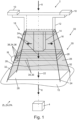
- Figure 1 shows a drone 2 in a highly simplified and purely symbolic representation. This serves to attack a target 4 using a shaped HPEM pulse 6 (symbolized by an arrow).
- the drone is a vertical take-off or landing drone and is therefore set up for a flight, in particular for a take-off or landing along a direction of gravity 8 (also symbolized by an arrow).
- the drone in the present case is equipped as a multicopter with several propellers 10, of which Figure 1 symbolically only two pieces are indicated.
- the propellers 10 are part of a basic body 12 of the drone.
- HPEM source 14 is a resonator. This is used to generate and emit an unshaped HPEM pulse 16 (also symbolized by arrows).
- the drone 2 is in a landing state ZL and is therefore resting or standing as intended on a flat surface 15 and is ready for use, ie for a vertical takeoff against the direction of gravity 8.
- the drone 2 contains a landing gear 18. This is designed to support the rest of the drone 2 (especially the base body 12) in the landing state ZL shown here.
- the landing gear 18 of the drone 2 has a total of four legs 24, which are attached to the base body 12 of the drone 2. The legs 24 are shown in the figure by thickened lines.
- the drone is in Figure 1 in a working state ZA, which is explained in more detail below.
- the drone 2 contains a horn 20 in addition to the base body 12.
- the horn 20 is connected downstream of the HPEM source 14 in terms of radiation, i.e. in relation to the HPEM pulse 16 or its radiation.
- the horn 20 is set up to guide or shape the HPEM pulse 16 emitted from the HPEM source 14 and radiated into the horn 20, to bundle and amplify it here, and to radiate it again in or along a beam direction 22 (also symbolized by an arrow and a dashed line) as the shaped HPEM pulse 6.
- a part of the horn 20 is formed by the landing gear 18 or a respective part of the four legs 24.
- the horn 20 is here or has the shape of a rectangular cross-section transverse to the beam direction 22, extending in Figure 4 funnel opening downwards. Two sides (in the figure the "rear” and “left") of the funnel are in the Figure 1 highlighted by dashed lines. With respect to a transverse direction to the beam direction 22, the horn 20 is therefore rectangular here.
- the beam direction 22 points in the direction of gravity 8. Irradiation of the target 4 with the shaped HPEM pulse 6 is only symbolically indicated here and refers to a flight of the drone 2 when it has left the landing state ZL.
- the beam direction 22 is firmly coupled to the geometry / position of the HPEM source 14 and horn 20 or base body 12, but also points in flight when the drone 2 is in the same orientation as in Fig.1 / Landing state ZL is "down".
- the horn 20 is partly formed by a section of the legs 24 in the form of a horn portion 26 of the legs 24.
- the horn is formed by a Horn body 28 is formed or completed, which is directly attached to the legs 24.
- the horn parts 26 of the legs 24 form four edges of the horn 20, and the horn body 28 forms its four flat sides.
- the horn part 26 of the legs corresponds to the hatched section of the legs 24.
- the legs 24 and the horn body 28 are designed separately from the base body 12 or the rest of the drone 2, namely they can be removed from it or attached to it.
- the horn 20 is designed here as a strut structure 30.
- the legs 24 or their horn parts 26 form rigid struts 32.
- Metallic wires stretched between the legs 24 form flexible struts 34 of the strut structure 30.
- the flexible struts 34 are held as cross struts 36 between the legs 24.
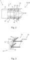
- Figure 2 shows - even more stylized - the drone 2 from Figure 1 , but now not in a working state ZA, but in a stowed state ZS.
- the drone has been tilted 90° to the left.
- drone 2 is not ready for use, but is prepared for transport.
- Figure 2 along with Figure 1 thus illustrates that the horn 20 together with the landing gear 18 can be changed between a working position PA in the working state ZA and a stowed position PS in the stowed state ZS.
- the stowed state ZS there is no longer an actual horn 20. This is because the horn portion 26 that was previously stretched between the legs 24 is here folded up limply or hangs down unstressed.
- the state is roughly comparable to a folded umbrella or a folded rotary clothes dryer.
- the course of the former horn 20 in its flaccid form is in Figure 2 indicated by dashed lines.
- the Figures 1 and 2 only a few of the struts 32, 34 are drawn, although these are densely and evenly distributed over the entire horn 20 in order to form the horn 20. Thanks to the flexible struts 34, a part of the horn 20, namely the horn body 28 between the legs 24, is flexible. In the working position PA, the horn body 28 is held in its shape forming the horn 20 due to tension between the legs 24.
- the shape here is, as explained above, the rectangular cross-section in the Figure 1 Horn funnels widening downwards.
- Figure 3 shows in detail how the struts 34 are formed by passing a wire 38 through openings 40 in the legs 24.
- the legs 24 are made of an electrically conductive material, in this case metal. This creates electrical contact between the respective wires 38 and the leg 24 and an inherently conductive horn 20 is thus formed.
- the leg 24 is made of an electrically insulating material.
- a connecting wire 42 is then provided. This runs along the leg 24 and contacts the respective wires 38 in order to electrically connect them to the overall conductive horn 20. Because it is an alternative embodiment, the connecting wire 42 is only indicated by dashed lines here.
- FIG. 4 shows another alternative drone 2, here in cross-section.
- the horn 20 or the horn body 28 is constructed here as a strut structure 30 from a fabric 44, here a flexible steel fabric. This is held in its shape in the working position PA due to tension. This in turn is achieved by attaching hooks 46 to the base body 12.
- Tension cables 48 here steel cables, connected to the fabric 44 are detachably hooked into these.
- (detachable) tension springs 50 are provided, which hold the horn body 28 in tension on the legs 24 or tension the horn 20 into its shape.
- the horn body 28 is therefore indirectly held on the legs 24.
- the legs 24 contribute to the horn 20 in that they hold, support or tension the horn body 28 here.
- the fabric 44 is thus again a strut structure 30 made of flexible struts 34 in the form of steel wires that are crossed with one another.
- the legs 24 and the horn 20 can be attached or removed from the base body 12 and the horn 20 can also be attached or removed from the legs 24.
- This drone 2 can also easily be moved to a stowed position PS (not shown) or a stowed state ZS, for example for transport purposes.
Landscapes
- Engineering & Computer Science (AREA)
- Radar, Positioning & Navigation (AREA)
- Remote Sensing (AREA)
- General Engineering & Computer Science (AREA)
- Physics & Mathematics (AREA)
- Electromagnetism (AREA)
- Aviation & Aerospace Engineering (AREA)
- Aerials With Secondary Devices (AREA)
Abstract
Description
- Die Erfindung betrifft eine Drohne zur Bekämpfung eines Ziels mit Hilfe eines HPEM-Pulses.
- Aus der
DE 10 2015 008 296 A1 ist eine solche Drohne in Form einer Abwehrdrohne zur Bekämpfung eines Ziels in Form der Abwehr einer Kleindrohne bekannt, umfassend: zumindest einen Motor zum Antrieb zumindest eines Propellers, einen mit dem Motor verbundenen Rumpf und eine am Rumpf befestigte HPEM-Einrichtung zur Erzeugung eines HPEM-Pulses in Form eines hochenergetischen elektromagnetischen Pulses, wobei eine Erkennungseinrichtung zur Erkennung der fliegenden Kleindrohne und zum automatischen Steuern in Richtung der Kleindrohne vorgesehen ist. - Aufgabe der vorliegenden Erfindung ist es, Verbesserungen in Bezug auf eine derartige Drohne zur Bekämpfung eines Ziels mithilfe eines HPEM Pulses anzugeben.
- Die Aufgabe wird gelöst durch eine Drohne gemäß Patentanspruch 1. Bevorzugte oder vorteilhafte Ausführungsformen der Erfindung sowie anderer Erfindungskategorien ergeben sich aus den weiteren Ansprüchen, der nachfolgenden Beschreibung sowie den beigefügten Figuren.
- Die Drohne dient bzw. ist eingerichtet zur Bekämpfung eines Ziels mithilfe eines geformten HPEM Pulses. Die Drohne ist zu einem Flug, insbesondere Start und/oder Landung, entlang einer Schwerkraftrichtung eingerichtet. Mit anderen Worten ist die Drohne zu einem Senkrechtstart und / oder einer Senkrechtlandung eingerichtet. Die Drohne ist daher insbesondere eine Helikopter- oder Multicopter-Drohne, zum Beispiel ein Quadrocopter oder Octocopter. Eine derartige Drohne wird auch unbemanntes Luftfahrzeug (unmanned aerial vehicle, UAV) genannt.
- Die Drohne enthält ein Landegestell. Das Landegestell ist dazu eingerichtet, die restliche Drohne (also die Drohne mit Ausnahme des Landegestells) in einem bestimmungsgemäßen Landezustand zu tragen. "Bestimmungsgemäß" heißt hier, dass die Drohne eben wie geplant bzw. vorgesehen auf dem Landegestell auf einem Untergrund steht und nicht z.B. umgestürzt ist. Ein solcher Landezustand ist also derjenige, wenn die Drohne sich in Ruhe befindet, also nicht fliegt und auf einem Untergrund ruht, z.B. vor einem Start oder nach einer Landung. Ein Landegestell ist insbesondere nötig, um mithilfe dessen einen Senkrechtstart oder eine Senkrechtlandung durchführen zu können. Mit anderen Worten kann die Drohne so ohne Zuhilfenahme sonstiger Haltevorrichtungen auf einem Untergrund landen oder von diesem abheben oder auf dem Untergrund ruhen.
- Die Drohne enthält eine HPEM Quelle. Diese dient bzw. ist eingerichtet zur Abstrahlung des oben genannten HPEM Pulses, jedoch in noch ungeformtem Zustand. Von der HPEM Quelle wird im Betrieb also zunächst der ungeformte HPEM-Puls ausgesendet.
- Zumindest in einem Arbeitszustand der Drohne gilt: die Drohne enthält ein Horn. Das Horn ist der HPEM Quelle strahlungstechnisch (bezogen auf die Abstrahlung des HPEM-Pulses) nachgeschaltet. Das Horn ist dazu eingerichtet, den aus der HPEM Quelle in das Horn eingestrahlten ungeformten HPEM Puls zu führen und in einer Strahlrichtung als geformten HPEM Puls wieder abzustrahlen. Die Strahlrichtung ist dabei fest am Horn bzw. der gesamten Drohne orientiert, gibt also an in welcher Relativrichtung zur Drohne der geformte HPEM-Puls abgestrahlt wird. Die strahlungstechnische Nachschaltung bezieht sich also auf den Strahlungsweg des zunächst ungeformt und später geformten Pulses.
- Der Arbeitszustand ist derjenige Zustand, in dem die Drohne dazu in der Lage ist, den HPEM-Puls auszusenden, und diesen durch das Horn zu formen. "Zumindest in dem Arbeitszustand" ist dabei stets so zu verstehen, dass die Drohne auch andere Zustände als den Arbeitszustand einnehmen kann. In diesen müssen dann die entsprechend genannten Eigenschaften jeweils nicht erfüllt sein. Zum Beispiel kann die Drohne auch einen Stauzustand einnehmen, in dem dann überhaupt kein eigentliches Horn vorhanden ist, da diese ungespannt, eingefaltet oder von der restlichen Drohne entfernt ist. Dies wird weiter unten näher erläutert.
- Zumindest in dem oben genannten Arbeitszustand ist zumindest ein Teil des Horns durch zumindest einen Teil des Landegestells gebildet.
- Der Beitrag, den das Landegestell zum Horn liefert kann entweder derart sein, dass tatsächlich ein struktureller Teil des Horns selbst durch das Bein gebildet wird, z.B. eine Längsstrebe / Rippe, siehe unten. Der Beitrag kann aber auch in einem rein mechanischen Beitrag bestehen, z.B. darin, dass eine das Horn bildende Struktur, z.B. ein Stahlgewebe, durch die Beine zumindest teilweise gehalten bzw. gespannt wird.
- Dank des Horns ist die Drohne dazu fähig, nicht nur den ungeformten, sondern einen durch das Horn geformten (die Formung geht insbesondere mit einer Verstärkung einher) HPEM Puls auszusenden. Die Bekämpfung von Zielen wird hierdurch verbessert.
- Zusätzlich erfolgt jedoch mit anderen Worten zumindest eine Teilintegration von Horn und Landegestell. Insgesamt wird so eine zumindest teilweise Doppelfunktionalität zwischen Horn und Landegestell erreicht, was insbesondere zu einer Material- und/oder Gewichtseinsparungen an der Drohne führen kann.
- In einer bevorzugten Ausführungsform weist die Strahlrichtung zumindest im bestimmungsgemäßen Landezustand der Drohne in Richtung der Schwerkraftrichtung. Der Landezustand wird hier zu Zwecken der Richtungsdefinition eingeführt. Denn in diesem Landezustand steht die Drohne auf ihrem Landegestell, was folgerichtig daher "nach unten", also in Richtung der Schwerkraft unterhalb eines Grundkörpers der Drohne angeordnet ist. Da auch das Horn in diese Richtung abstrahlen soll, ist dieses auch "unten" an der Drohne angeordnet. Somit ist die zumindest teilweise Integration von Landegestellt und Horn besonders vorteilhaft.
- All dies gilt selbstverständlich wieder ggf. zumindest im Arbeitszustand, wenn ein Horn tatsächlich vorhanden ist. Voraussetzung für diese Ausführungsform ist jedenfalls, dass das Horn insofern vollständig besteht, dass diesem die Strahlrichtung zugeordnet ist. Mit anderen Worten zeigt die Strahlrichtung an der Drohne also "nach unten" bzw. in eine Landerichtung.
- In einer bevorzugten Ausführungsform ist das Horn (zumindest im Arbeitszustand, siehe oben) bezüglich der Strahlrichtung im Querschnitt rund oder oval oder eckig ausgeführt. Die entsprechende Form bezieht sich zumindest auf eine Horn-Grundform, -Einhüllende bzw. Flächenform des Horns. Dies gilt z.B. dann wenn das Horn nur zum Teil durch Material tatsächlich gebildet ist und ansonsten auch Auslassungen / Durchbrechungen aufweist. Dies gilt zum Beispiel, wenn das Horn als Draht-, Rippen- oder Strebenkonstruktion / Gitter / Gewebe / Käfig usw. ausgeführt ist, wie weiter unten erläutert wird. Die eckige Form ist insbesondere eine viereckige, insbesondere rechteckige, insbesondere quadratische Form. Derartige Hornformen haben sich in der Praxis als besonders effektiv erwiesen.
- In einer bevorzugten Ausführungsform ist das Horn zusammen mit dem Landegestell zwischen einer Stauposition (Horn/Landegestell in einem Stauzustand) und der Arbeitsposition (Horn/Landegestell in einem Arbeitszustand) veränderbar. Wenigstens sind Horn und Landegestell dabei von der Arbeitsposition in die Stauposition oder aus der Stauposition in die Arbeitsposition bringbar. Die Veränderbarkeit ist zum Beispiel eine Teleskopierbarkeit, Klappbarkeit, Verformbarkeit oder sonstige Formänderung. Wie oben erläutert ist in der Stauposition dann gegebenenfalls überhaupt kein tatsächliches Horn mehr vorhanden, sondern vielmehr nur noch ein erst in der Arbeitsposition wieder zu dem Horn hin veränderbares / transformierbares Horn-Grundelement. Ein solches ist z.B. das weiter unten genannte Hornelement, zum Beispiel eine eingefaltete Struktur, die erst in der Arbeitsposition wieder zu einem tatsächlichen Horn entfaltbar ist. Zum Beispiel könnte das Horn nach Art eines Regenschirms oder einer Wäschespinne in der Arbeitsposition aufgespannt und in der Stauposition eingefaltet, zusammengelegt sein usw. Eine entsprechende Stauposition vereinfacht zum Beispiel den Transport einer entsprechenden Drohne.
- In einer bevorzugten Ausführungsform weist das Landegestell wenigstens drei, insbesondere vier, an einem Grundkörper der Drohne befestigte Beine auf. Das Horn ist dann durch zumindest einen Hornanteil der Beine und einen an den Beinen angebrachten (unmittelbar oder mittelbar) Hornkörper gebildet. Der Hornanteil ist also ein Abschnitt oder Teil des jeweiligen Beins, der einen Beitrag zum Horn liefert. Ein zumindest Teil der Beine bildet also zumindest einen Teil des Horns. Zusammen mit dem Hornkörper ergibt sich dann insbesondere bereits das gesamte Horn. Der Hornkörper kann z.B. ein metallisches Geflecht, eine Platte oder Folie oder eine Reihe paralleler gespannter Drähte sein.
- Wenigstens eines, insbesondere alle, der Beine kann dabei ein elektrisch leitendes Material, zum Beispiel Metall, enthalten oder aus diesem bestehen. Insbesondere ist dieser metallische Teil geeignet, einen Teil des Horns, z.B. eine Längsstrebe, zu bilden. Wenigstens eines, insbesondere alle, der Beine kann jedoch auch aus einem elektrisch nichtleitenden Material bestehen oder dieses enthalten, wie zum Beispiel einen Harz-Faserwerkstoff oder Kunststoff. In diesem Fall leistet das Bein insbesondere einen mechanischen Trage- oder Stützbeitrag zum Horn. Dann kann zum Beispiel ein zusätzlicher elektrischer Leiter am Bein oder parallel zum Bein vorgesehen sein, um sonstige Komponenten des Horns, z.B. gespannte Querdrähte, im Bereich der Beine elektrisch leitend zu einem Horn zu komplettieren.
- Beine als zumindest Teil eines Landegestells für eine Drohne haben sich in der Praxis etabliert.
- In einer bevorzugten Variante dieser Ausführungsform sind die Beine und / oder der Hornkörper von dem Grundkörper separat ausgeführt. Insbesondere sind diese also am Grundkörper anbringbar und / oder von diesem abnehmbar. Auch dies vereinfacht beispielsweise den Transport einer Drohne.
- In einer bevorzugten Variante dieser Ausführungsform ist wenigstens eines der Beine an dem Grundkörper schwenkbar angebracht. Die Schwenkung kann dabei insbesondere um eine, aber auch um mehrere Achsen erfolgen. Insbesondere ist also das Bein zwischen der oben genannten Arbeitsposition und der Stauposition schwenkbar. Insbesondere sind alle Beine schwenkbar angebracht; oder zumindest alle bis auf eines.
- In einer bevorzugten Ausführungsform ist das Horn zumindest teilweise als eine Strebenstruktur ausgeführt, also eine zumindest teilweise aus einzelnen Streben (Rippen, Zweigen, Ästen, Filamenten usw.) aufgebaut. Insbesondere ist in Kombination mit der o.g. Ausführungsform der Hornkörper und/oder der Hornanteil zumindest teilweise als eine Strebenstruktur ausgeführt. Die Strebenstruktur ist insbesondere gebildet durch Streben bzw. eine Netz- / Gitterstruktur aus gekreuzten und / oder nicht gekreuzten, insbesondere parallelen Streben. Insbesondere existieren also gekreuzte netzartige oder nebeneinander verlaufende parallele Streben innerhalb der Strebenstruktur. Insbesondere bildet der o.g. Hornanteil eine Reihe von ersten Streben. Der Hornkörper bildet dann eine Reihe von hierzu nicht parallel verlaufenden zweiten "Quer-"Streben. So lässt sich insbesondere die oben genannte Struktur nach Art einer Wäschespinne besonders vorteilhaft aufbauen.
- In einer bevorzugten Ausführungsform ist die Strebenstruktur zumindest teilweise durch wenigstens eine flexible Strebe und / oder wenigstens eine starre Strebe gebildet. So ergibt sich insbesondere wieder die o.g. Struktur der "Wäschespinne" mit den starren Streben in Form der Arme der Wäschespinne und den flexiblen Streben in Form der an den Armen gehaltenen Wäscheleine. Flexible Streben sind zum Beispiel in Form von Filamenten oder Drähten ausgeführt. Starre Streben sind zum Beispiel in Form von Stangen bzw. Hornanteilen von Beinen ausgeführt. Insbesondere können durch eine Kombination von starren und flexiblen Streben falt- bzw. aufspannbare Horn-Ausführungsformen nach Art der o.g. Wäschespinne / Regenschirm usw. besonders vorteilhaft erstellt werden. Insbesondere sind die flexiblen Streben dann in der Arbeitsposition auf Zug gerade verlaufend gespannt und nehmen somit eine definierte Ortsposition bzw. Form ein.
- In einer bevorzugten Variante einer Kombination beider Ausführungsform oben ist die Strebenstruktur dadurch gebildet, dass Querstreben zwischen den Beinen gehalten sind. Die Streben sind dann zumindest teilweise als flexible Filamente ausgeführt, insbesondere wenn die Beine schwenkbar sind. So können diese in der Arbeitsposition (Ausschwenken der Beine) gespannt und in der Stauposition (Beine eingeschwenkt) flexibel entspannt zu sein. Insbesondere weisen die Beine Durchführungen auf, um Streben, z.B. in Form von Drähten, aufzunehmen. Insbesondere ist dabei ein Draht über mehrere Beine durchgehend geführt, umläuft die Drohne das Horn bildend also in Umfangsrichtung um die Strahlrichtung.
- In einer bevorzugten Ausführungsform ist also ganz allgemein zumindest ein Teil des Horns, insbesondere der Hornkörper, flexibel ausgeführt. Der Hornkörper bzw. der betreffende Anteil des Horns ist dann in der Arbeitsposition insbesondere auf Zug gespannt, entfaltet, glatt, jedoch faltbar, knickbar, biegbar, um in eine andere als die Arbeitsposition zu gelangen, insbesondere in die Stauposition. Hierzu eignet sich insbesondere die oben genannte Streben- / Netz- / Gitterstruktur, eine Folie, ein Gewebe usw.
- In einer bevorzugten Variante beider oben genannten Ausführungsform ist der Hornkörper, insbesondere als Anteil der Strebenstruktur, zumindest in dem Arbeitszustand bzw. der Arbeitsposition aufgrund von Zug in seiner das Horn bildenden Form gehalten. Insbesondere ist der Hornkörper dabei zwischen wenigstens einem der Beine und/oder dem Grundkörper der Drohne auf Zug gehalten. Mit anderen Worten gleicht der Hornkörper im Arbeitszustand bzw. in der Arbeitsposition dann einem gespannten Netz / Gewebe / Folie mit z.B. gespannten Drähten und Streben bzw. bildet eine Gitter- oder eine Rippenstruktur.
- Die Erfindung beruht auf folgenden Erkenntnissen, Beobachtungen bzw. Überlegungen und weist noch die nachfolgenden bevorzugten Ausführungsformen auf. Diese Ausführungsformen werden dabei teils vereinfachend auch "die Erfindung" genannt.
- Die Ausführungsformen können hierbei auch Teile oder Kombinationen der oben genannten Ausführungsformen enthalten oder diesen entsprechen und/oder gegebenenfalls auch bisher nicht erwähnte Ausführungsformen einschließen.
- Die Erfindung beruht auf der Erkenntnis, dass zum gefahrlosen Landen einer HPEM-Drohne (zum Aussenden eines HPEM-Pulses) ein Landegestell benötigt wird. Andererseits wird an der gleichen Position / Seite der Drohne (also "unten", dort wo sich das Landegestell befindet) ein Horn benötigt bzw. ist ein solches gewünscht, um einen HPEM Puls eines Resonators (HPEM Quelle) gezielt zu verstärken. "Gleiche Position" ist also so zu verstehen: im Bereich des Landegestells, wenn eine Abstrahlung der Pulse "nach unten" (Bezug auf eine bestimmungsgemäße Lande-/Ruhelage der Drohne) gewünscht ist. Ein Metallgestell als Landegestell (z.B. vier Metallbeine) führt dabei zu metallischen Reflexionen. Ein zusätzliches Kunststoffgestell zusätzlich zu einem herkömmlichen Horn schränkt den Bauraum des Horns ein.
- Die Erfindung beruht daher auf der Idee einer Kombination beider Funktionen, nämlich des gefahrlosen Landens und des Verstärkens des HPEM Pulses, in einem (zumindest teilweise kombinierten) einzigen Bauteil / Baugruppe, nämlich durch ein Landegestell mit wenigstens metallischen Anteilen, welches wie ein Horn geformt ist bzw. als Horn wirkt.
- Gemäß der Erfindung erfolgt ein Reichweitengewinn der HPEM-Quelle ohne Verzicht auf ein Landegestell bei Gewichts- und Bauraumoptimierung. Es erfolgt eine Verbringung eines Horns in eine Drohnenlandeplattform. Insbesondere ist die Drohne im Sinne der oben genannten
DE 10 2015 008 296 A1 zur autonomen Detektion und Bekämpfung eines Ziels in Form einer Target-Drohne, ertüchtigt. - Gemäß der Erfindung lässt sich zum Beispiel ein Verstärkungsfaktor von 3dB zwischen dem ungeformten HPEM-Puls und dem geformten HPEM-Puls erreichen. Insbesondere sind die Beine der Landeplattform bzw. Landegestells aus Metall hergestellt. Insbesondere befinden sich jedoch innerhalb des Horns - zumindest in der Arbeitsposition - keinerlei weitere metallische Bauteile, insbesondere Bestandteile eines Landegestells, welche in Wirkrichtung der HPEM Quelle (zum Beispiel eines Resonators) Reflexionen verursachen könnten.
- Gemäß der Erfindung ergibt sich also ein Landegestell einer Drohne mit einem integrierten Horn bzw. entspricht das Landegestell zumindest teilweise einem Horn.
- Gemäß der Erfindung ergibt sich ein Horn zur Verstärkung einer HPEM-Quelle (des von dieser abgestrahlten ungeformten HPEM Pulses), auf welchem die Drohne wie bei einem konventionellen Landegestell landen kann. Die vorliegende Erfindung verbessert insbesondere die Abwehr von Kleindrohnen mittels luftgestützte HPEM-Technologie, insbesondere also eine Abwehrdrohne gemäß der
DE 10 2015 008 296 A1 . - Gemäß der Erfindung ergibt sich insbesondere: eine Drohne in Form einer Abwehrdrohne zur Abwehr einer Kleindrohne, insbesondere eines ferngesteuerten Helikopters, umfassend auch die Ausführungsformen der
DE 10 2015 008 296 A1 . Es ergibt sich eine Drohne mit einem Landegestell, welches zeitgleich bzw. in einer Doppelfunktion als bzw. zur Verstärkung des HPEM Pulses dient, vergleichbar einer Hornantenne ("Horn"). Es ergibt sich eine Drohne mit einem Horn, welches insbesondere in der Arbeitsposition einen Öffnungswinkel von mindestens 5° und maximal 85°, vorzugsweise 30° verfügt. Es ergibt sich eine Abwehr-Drohne, welche ein rundes, ovales oder eckig geformtes Horn verwendet bzw. über ein solches verfügt. Es ergibt sich eine Abwehrdrohne, welche mithilfe von Software autonom fliegt, Targets (Ziele) ausfindig macht und insbesondere nach Patentanspruch 4 derDE 10 2015 008 296 A1 die Auslöseeinrichtung selbständig aktiviert und deaktiviert. - Es wird daher auf folgendes anmeldungsfremde Dokument verwiesen:
Die Drohne ist insbesondere eine Abwehrdrohne zur Abwehr einer Kleindrohne, welche Abwehrdrohne in verschiedenen Ausführungsformen in derDE 10 2015 008 296 A1 offenbart ist: Alle Ausführungsformen der Abwehrdrohne derDE 10 2015 008 296 A1 , insbesondere die Ausführungsformen gemäß der elf Patentansprüche derDE 10 2015 008 296 A1 , stellen daher bevorzugte Ausführungsformen der vorliegend beanspruchten Drohne dar. - Das Dokument
DE 10 2015 008 296 A1 wird hiermit vollständig durch Verweisung in die vorliegende Patentanmeldung einbezogen. Alle technischen Merkmale des in Bezug genommenen Dokuments sollen damit zur Lehre der vorliegenden Erfindung gehören. Dies gilt insbesondere insofern, dass das vorliegend offenbarte Horn der inDE 10 2015 008 296 A1 offenbarten HPEM-Einrichtung nachgeschaltet ist, um den hochenergetischen elektromagnetischen Puls in der Strahlrichtung abzustrahlen. Zumindest ein Teil des Horns ist dann als ein zumindest Teil des Landegestells der Abwehrdrohne ausgebildet. - Mit anderen Worten wird die Abwehrdrohne der
DE 10 2015 008 296 A1 um das vorliegend offenbarte Horn erweitert, das zumindest teilweise auch zumindest Teil eines vorliegend offenbarten Landegestells der Abwehrdrohne ist. Zu bekämpfendes Ziel ist dann die Kleindrohne. - Weitere Merkmale, Wirkungen und Vorteile der Erfindung ergeben sich aus der nachfolgenden Beschreibung eines bevorzugten Ausführungsbeispiels der Erfindung sowie der beigefügten Figuren. Dabei zeigen, jeweils in einer schematischen Prinzipskizze:
- Figur 1
- stark schematisiert eine Drohne mit Horn in einer perspektivischen Prinzipdarstellung,
- Figur 2
- die Drohne aus
Figur 1 um 90° nach links verkippt und in eine Stauposition verbracht, - Figur 3
- als Detail III aus
Figur 1 einen Ausschnitt aus einem Bein der Drohne, - Figur 4
- eine alternative Drohne im Querschnitt.
-
Figur 1 zeigt in stark vereinfachter und rein symbolischer Darstellung eine Drohne 2. Diese dient zur Bekämpfung eines Ziels 4 mithilfe eines geformten HPEM-Pulses 6 (symbolisiert durch einen Pfeil). Die Drohne ist eine Senkrechtstart- bzw. -lande-Drohne und ist daher zu einem Flug, insbesondere zu einem Start bzw. einer Landung entlang einer Schwerkraftrichtung 8 (auch durch einen Pfeil symbolisiert) eingerichtet. Hierzu ist die Drohne im vorliegenden Fall als Multicopter mit mehreren Propellern 10 ausgerüstet, von denen inFigur 1 symbolisch nur zwei Stück angedeutet sind. Die Propeller 10 sind Teil eines Grundkörpers 12 der Drohne. - Ein weiterer Teil des Grundkörpers 12 und damit der Drohne 2 ist eine HPEM-Quelle 14, hier ein Resonator. Diese dient zur Erzeugung und Abstrahlung eines ungeformten HPEM-Pulses 16 (auch durch Pfeile symbolisiert).
- Die Drohne 2 befindet sich in einem Landezustand ZL und ruht bzw. steht daher bestimmungsgemäß auf einem ebenen Untergrund 15 und ist für einen Einsatz, d.h. für einen Senkrecht-Start entgegen der Schwerkraftrichtung 8, bereit.
- Die Drohne 2 enthält neben dem Grundkörper 12 ein Landegestell 18. Dieses ist dazu eingerichtet, die restliche Drohne 2 (vor allem den Grundkörper 12) in dem vorliegend dargestellten Landezustand ZL zu tragen. Das Landegestell 18 weist bei der Drohne 2 insgesamt vier Beine 24 auf, welche am Grundkörper 12 der Drohne 2 befestigt sind. Die Beine 24 sind in der Figur durch verdickte Linien dargestellt.
- Die Drohne ist in
Figur 1 in einem Arbeitszustand ZA dargestellt, was weiter unten noch näher erläutert wird. In dem Arbeitszustand ZA enthält die Drohne 2 neben dem Grundkörper 12 weiterhin auch ein Horn 20. Das Horn 20 ist der HPEM Quelle 14 strahlungstechnisch, d.h. in Bezug auf den HPEM-Puls 16 bzw. dessen Abstrahlung, nachgeschaltet. Das Horn 20 ist dazu eingerichtet, den aus der HPEM Quelle 14 ausgestrahlten und in das Horn 20 eingestrahlten HPEM Puls 16 zu führen bzw. zu formen, hier zu bündeln und zu verstärken, und in bzw. entlang einer Strahlrichtung 22 (auch durch einen Pfeil und eine gestrichelte Linie symbolisiert) als den geformten HPEM Puls 6 wieder abzustrahlen. - Ein Teil des Horns 20 ist hierbei durch das Landegestell 18 bzw. einen jeweiligen Teil der vier Beine 24 gebildet. Das Horn 20 ist hier bzw. hat die Form eines im Querschnitt quer zur Strahlrichtung 22 rechteckigen, sich in
Figur 4 nach unten hin öffnenden Trichters. Zwei Seiten (in der Figur die "hintere" und "linke") des Trichters sind in derFigur 1 durch Strichelung hervorgehoben. Bezüglich einer Querrichtung zur Strahlrichtung 22 ist das Horn 20 also hier rechteckig ausgeführt. - Im Landezustand ZL weist die Strahlrichtung 22 in Richtung der Schwerkraftrichtung 8. Eine Bestrahlung des Ziels 4 mit dem geformten HPEM Puls 6 ist hier nur symbolisch angedeutet, und bezieht sich auf einen Flug der Drohne 2, wenn diese den Landezustand ZL verlassen hat. Die Strahlrichtung 22 ist fest an die Geometrie / Lage von HPEM Quelle 14 und Horn 20 bzw. Grundkörper 12 gekoppelt, zeigt jedoch auch im Flug, wenn die Drohne 2 sich in der gleichen Orientierung wie in
Fig. 1 / Landezustand ZL befindet, "nach unten". - Die Beine 24 ragen am in der
Figur 1 unteren Ende etwas aus dem Horn 20 heraus. Im Landezustand ZL sitzen daher die Beine 24 mit ihren in der Figur unteren Enden, nicht jedoch das Horn 20, auf dem Untergrund 15 auf. - Das Horn 20 ist hierbei zum Teil durch einen Teilabschnitt der Beine 24 in Form eines Hornanteils 26 der Beine 24 gebildet. Andererseits ist das Horn durch einen Hornkörper 28 gebildet bzw. vervollständigt, der an den Beinen 24 unmittelbar angebracht ist. Vorliegend bilden also die Hornanteile 26 der Beine 24 vier Kanten des Horns 20, der Hornkörper 28 dessen vier ebene Flachseiten. In der Figur entspricht der Hornanteil 26 der Beine dem schraffiert gekennzeichneten Abschnitt der Beine 24. Vorliegend sind die Beine 24 und der Hornkörper 28 separat von dem Grundkörper 12 bzw. der restlichen Drohne 2 ausgeführt, nämlich von diesem abnehmbar bzw. an diesem anbringbar.
- Das Horn 20 ist hier als eine Strebenstruktur 30 ausgeführt. Die Beine 24 bzw. deren Hornanteile 26 bilden hierbei starre Streben 32. Zwischen den Beinen 24 gespannte metallische Drähte bilden flexible Streben 34 der Strebenstruktur 30. Die flexiblen Streben 34 sind hierbei als Querstreben 36 zwischen den Beinen 24 gehalten.
-
Figur 2 zeigt - nochmals stärker stilisiert - die Drohne 2 ausFigur 1 , nun jedoch nicht in einem Arbeitszustand ZA, sondern in einem Stauzustand ZS. Die Drohne ist hierzu um 90° nach links verkippt worden. In dem Stauzustand ZS ist die Drohne 2 nicht einsatzbereit, sondern zum Transport hergerichtet. - Aufgrund der flexiblen Streben 34 ist es möglich, dass das "Horn 20" gemäß
Figur 2 eine Stauposition PS einnimmt, in der die entsprechenden Drähte (vormals Querstreben 36) lose werden, also nicht mehr zwischen den Beinen 24 straff bzw. gerade gespannt sind, sondern schlaff durchhängen. Aus diesem Grund verliert das Horn 20 auch seine Form bzw. existiert als solches dann nicht mehr in dem Stauzustand ZS. -
Figur 2 zusammen mitFigur 1 illustriert also, dass das Horn 20 zusammen mit dem Landegestell 18 zwischen einer Arbeitsposition PA in dem Arbeitszustand ZA und einer Stauposition PS in dem Stauzustand ZS veränderbar ist. Im Stauzustand ZS ist kein eigentliches bzw. tatsächliches Horn 20 mehr vorhanden. Denn der zwischen den Beinen 24 vormals aufgespannte Hornanteil 26 ist hier schlaff zusammengefaltet bzw. hängt ungespannt durch. Der Zustand ist in etwa vergleichbar mit einem zusammengefalteten Regenschirm oder einer zusammengeklappten Wäschespinne. Der Verlauf des einstmaligen Horns 20 in seiner schlaffen Form ist inFigur 2 gestrichelt angedeutet. - Der Übergang zwischen Stauposition PS und Arbeitsposition PA ist deshalb möglich, da die Beine 24 an dem Grundkörper 12 schwenkbar angebracht sind, also ausgehend von
Figur 1 bezüglich der Strahlrichtung 22 radial einwärts einschwenkbar sind. - Aus Gründen der Übersichtlichkeit sind in den
Figuren 1 und2 jeweils nur wenige der Streben 32, 34 gezeichnet, obschon diese über das gesamte Horn 20 dicht und gleichmäßig verteilt sind, um das Horn 20 auszubilden. Dank der flexiblen Streben 34 ist also ein Teil des Horns 20, hier nämlich der Hornkörper 28 zwischen den Beinen 24 flexibel ausgeführt. In der Arbeitsposition PA ist der Hornkörper 28 aufgrund von Zug zwischen den Beinen 24 in seiner das Horn 20 bildenden Form gehalten. Die Form ist hier wie oben erläutert der im Querschnitt rechteckige sich in derFigur 1 nach unten erweiternde Horntrichter. -
Figur 3 zeigt im Detail, wie die Streben 34 dadurch gebildet sind, dass ein Draht 38 durch Durchbrechungen 40 in den Beinen 24 hindurchgeführt ist. Die Beine 24 sind hier aus elektrisch leitendem Werkstoff, hier Metall hergestellt. Hierdurch entsteht elektrischer Kontakt zwischen den jeweiligen Drähten 38 und dem Bein 24 und ein in sich leitfähiges Horn 20 wird so gebildet. In einer alternativen Ausführungsform ist das Bein 24 aus elektrisch isolierendem Material hergestellt. Um das Horn 20 elektrisch leitend zu komplettieren, ist dann ein Verbindungsdraht 42 vorgesehen. Dieser verläuft entlang des Beines 24 und kontaktiert die jeweiligen Drähte 38, um diese zum insgesamt leitfähigen Horn 20 elektrisch zu verbinden. Weil eine alternative Ausführungsform, ist der Verbindungsdraht 42 hier nur gestrichelt angedeutet. -
Figur 4 zeigt eine weitere alternative Drohne 2, hier im Querschnitt. Das Horn 20 bzw. der Hornkörper 28 ist hier als Strebenstruktur 30 aus einem Gewebe 44, hier einem flexiblen Stahlgewebe, aufgebaut. Dieses ist aufgrund von Zug in seiner Form in der Arbeitsposition PA gehalten. Dies wiederum ist dadurch bewerkstelligt, dass am Grundkörper 12 Haken 46 angebracht sind. In diese sind mit dem Gewebe 44 verbundene Zugseile 48, hier Stahlseile, lösbar eingehängt. Weiterhin sind (lösbare) Zugfedern 50 vorgesehen, welche den Hornkörper 28 an den Beinen 24 auf Zug halten bzw. das Horn 20 in seine Form spannen. Hier ist der Hornkörper 28 also mittelbar an den Beinen 24 gehalten. Die Beine 24 leisten insofern einen Beitrag zum Horn 20, dass sie den Hornkörper 28 hier halten, tragen bzw. spannen. Das Gewebe 44 ist also wieder eine Strebenstruktur 30 aus hier zueinander gekreuzten flexiblen Streben 34 in Form von Stahldrähten. Auch hier sind Beine 24 sowie das Horn 20 wieder am Grundkörper 12 und das Horn 20 auch an den Beinen 24 anbringbar bzw. abnehmbar. - So kann auch diese Drohne 2 leicht in eine nicht dargestellte Stauposition PS bzw. einen Stauzustand ZS verbracht werden, zum Beispiel zu Transportzwecken.
-
- 2
- Drohne
- 4
- Ziel
- 6
- HPEM-Puls (geformt)
- 8
- Schwerkraftrichtung
- 10
- Propeller
- 12
- Grundkörper
- 14
- HPEM-Quelle
- 15
- Untergrund
- 16
- HPEM-Puls (ungeformt)
- 18
- Landegestell
- 20
- Horn
- 22
- Strahlrichtung
- 24
- Bein
- 26
- Hornanteil
- 28
- Hornkörper
- 30
- Strebenstruktur
- 32
- Strebe (starr)
- 34
- Strebe (flexibel)
- 36
- Querstrebe
- 38
- Draht
- 40
- Durchbrechung
- 42
- Verbindungsdraht
- 44
- Gewebe
- 46
- Haken
- 48
- Zugseil
- ZL
- Landezustand
- ZA
- Arbeitszustand
- ZS
- Stauzustand
- PS
- Stauposition
- PA
- Arbeitsposition
Claims (12)
- Drohne (2) zur Bekämpfung eines Ziels (4) mit Hilfe eines geformten HPEM-Pulses (6),- wobei die Drohne (2) zu einem Flug entlang einer Schwerkraftrichtung (8) eingerichtet ist,- mit einem Landegestell (18), das dazu eingerichtet ist, die restliche Drohne (2) in einem bestimmungsgemäßen Landezustand (ZL) zu tragen,- mit einer HPEM-Quelle (14) zur Abstrahlung des ungeformten HPEM-Pulses (16),- wobei zumindest in einem Arbeitszustand (ZA) der Drohne (2):- die Drohne ein Horn (20) enthält, das der HPEM-Quelle (14) strahlungstechnisch nachgeschaltet ist und das dazu eingerichtet ist, den aus der HPEM-Quelle (14) in das Horn (20) eingestrahlten ungeformten HPEM-Puls (16) zu führen und in einer Strahlrichtung (22) als geformten HPEM-Puls (6) wieder abzustrahlen, und- zumindest ein Teil des Horns (20) durch zumindest einen Teil des Landegestells (18) gebildet ist.
- Drohne (2) nach Anspruch 1,
dadurch gekennzeichnet,
dass die Strahlrichtung (22) zumindest im Landezustand (ZL) in Richtung der Schwerkraftrichtung (8) weist. - Drohne (2) nach einem der vorhergehenden Ansprüche,
dadurch gekennzeichnet,
dass das Horn (20) bezüglich der Strahlrichtung (22) im Querschnitt rund oder oval oder eckig ausgeführt ist. - Drohne (2) nach einem der vorhergehenden Ansprüche,
dadurch gekennzeichnet,
dass das Horn (20) zusammen mit dem Landegestell (18) zwischen einer Stauposition (PS) in einem Stauzustand (ZS) und einer Arbeitsposition (PA) in dem Arbeitszustand (ZA) veränderbar ist. - Drohne (2) nach einem der vorhergehenden Ansprüche,
dadurch gekennzeichnet,
dass das Landegestell (18) wenigstens drei an einem Grundkörper (12) der Drohne (2) befestigte Beine (24) aufweist und das Horn (20) durch zumindest einen Hornanteil (26) der Beine (24) und einen an den Beinen (24) angebrachten Hornkörper (28) gebildet ist. - Drohne (2) nach Anspruch 5,
dadurch gekennzeichnet,
dass die Beine (24) und / oder der Hornkörper (28) von dem Grundkörper (12) separat ausgeführt ist. - Drohne (2) nach einem der Ansprüche 5 bis 6,
dadurch gekennzeichnet,
dass wenigstens eines der Beine (24) an dem Grundkörper (12) schwenkbar angebracht ist. - Drohne (2) nach einem der vorhergehenden Ansprüche,
dadurch gekennzeichnet,
dass das Horn (20) zumindest teilweise als eine Strebenstruktur (30) ausgeführt ist. - Drohne (2) nach Anspruch 8,
dadurch gekennzeichnet,
dass die Strebenstruktur (30) zumindest teilweise durch wenigstens eine flexible Strebe (34) und / oder wenigstens eine starre Strebe (32) gebildet ist. - Drohne (2) nach einem der Ansprüche 8 bis 9 in Verbindung mit einem der Ansprüche 5 bis 7,
dadurch gekennzeichnet,
dass die Strebenstruktur (30) dadurch gebildet ist, dass Querstreben (36) zwischen den Beinen (24) gehalten sind. - Drohne (2) nach einem der vorhergehenden Ansprüche,
dadurch gekennzeichnet,
dass zumindest ein Teil des Horns (20) flexibel ist. - Drohne (2) nach Anspruch 11 in Verbindung mit einem der Ansprüche 5 bis 6,
dadurch gekennzeichnet,
dass der Hornkörper (28) zumindest in dem Arbeitszustand (ZA) aufgrund von Zug in seiner das Horn (20) bildenden Form gehalten ist.
Applications Claiming Priority (1)
| Application Number | Priority Date | Filing Date | Title |
|---|---|---|---|
| DE102022004723.3A DE102022004723A1 (de) | 2022-12-15 | 2022-12-15 | HPEM-Drohne mit am Landegestell integrierten Horn |
Publications (2)
| Publication Number | Publication Date |
|---|---|
| EP4385908A1 true EP4385908A1 (de) | 2024-06-19 |
| EP4385908B1 EP4385908B1 (de) | 2025-03-26 |
Family
ID=89119394
Family Applications (1)
| Application Number | Title | Priority Date | Filing Date |
|---|---|---|---|
| EP23214210.9A Active EP4385908B1 (de) | 2022-12-15 | 2023-12-05 | Hpem-drohne mit am landegestell integrierten horn |
Country Status (2)
| Country | Link |
|---|---|
| EP (1) | EP4385908B1 (de) |
| DE (1) | DE102022004723A1 (de) |
Citations (4)
| Publication number | Priority date | Publication date | Assignee | Title |
|---|---|---|---|---|
| DE102015008296A1 (de) | 2015-06-26 | 2016-12-29 | Diehl Bgt Defence Gmbh & Co. Kg | Abwehrdrohne zur Abwehr von Kleindrohnen |
| US20200363167A1 (en) * | 2019-05-17 | 2020-11-19 | The United States Of America, As Represented By The Secretary Of The Navy | Counter uav drone system using electromagnetic pulse |
| US20210356237A1 (en) * | 2020-05-15 | 2021-11-18 | Joshua Priest | Unmanned Aerial Vehicle with Electromagnetic Pulse Transmitter |
| US20220146236A1 (en) * | 2020-11-10 | 2022-05-12 | Diehl Defence Gmbh & Co. Kg | Horn antenna and method for reconstructing a horn antenna |
Family Cites Families (6)
| Publication number | Priority date | Publication date | Assignee | Title |
|---|---|---|---|---|
| KR101679752B1 (ko) * | 2016-06-14 | 2016-12-06 | 주식회사 한국기술연구소 | 무인기 격추 시스템 |
| DE102018004568B4 (de) * | 2018-06-08 | 2024-02-01 | Diehl Defence Gmbh & Co. Kg | Strahlungsquelle für Mikrowellen-Pulse und Strahlungseinrichtung |
| DE102018008381B4 (de) * | 2018-10-19 | 2020-08-06 | Diehl Defence Gmbh & Co. Kg | HPEM-Quelle, Fahrzeug und Verfahren |
| CN209197576U (zh) * | 2018-11-19 | 2019-08-02 | 辽宁通用航空研究院 | 一种高精度反无人机系统 |
| KR102001181B1 (ko) * | 2019-03-13 | 2019-07-17 | 유콘시스템 주식회사 | 무허가 드론을 격추시키는 드론 |
| DE102020006889A1 (de) * | 2020-11-10 | 2022-05-12 | Diehl Defence Gmbh & Co. Kg | Wirkvorrichtung zum Bekämpfen eines Ziels mittels elektromagnetischer Impulse, Wirkvorrichtungssystem, Trägereinrichtung und Verfahren zum Betreiben einer Wirkvorrichtung |
-
2022
- 2022-12-15 DE DE102022004723.3A patent/DE102022004723A1/de active Pending
-
2023
- 2023-12-05 EP EP23214210.9A patent/EP4385908B1/de active Active
Patent Citations (4)
| Publication number | Priority date | Publication date | Assignee | Title |
|---|---|---|---|---|
| DE102015008296A1 (de) | 2015-06-26 | 2016-12-29 | Diehl Bgt Defence Gmbh & Co. Kg | Abwehrdrohne zur Abwehr von Kleindrohnen |
| US20200363167A1 (en) * | 2019-05-17 | 2020-11-19 | The United States Of America, As Represented By The Secretary Of The Navy | Counter uav drone system using electromagnetic pulse |
| US20210356237A1 (en) * | 2020-05-15 | 2021-11-18 | Joshua Priest | Unmanned Aerial Vehicle with Electromagnetic Pulse Transmitter |
| US20220146236A1 (en) * | 2020-11-10 | 2022-05-12 | Diehl Defence Gmbh & Co. Kg | Horn antenna and method for reconstructing a horn antenna |
Non-Patent Citations (1)
| Title |
|---|
| USHAKOV V N ET AL: "Project start-up for ultra wideband radar based on ultrashort pulse plasma generator", 2017 RADIATION AND SCATTERING OF ELECTROMAGNETIC WAVES (RSEMW), IEEE, 26 June 2017 (2017-06-26), pages 27 - 281, XP033251905, DOI: 10.1109/RSEMW.2017.8103649 * |
Also Published As
| Publication number | Publication date |
|---|---|
| DE102022004723A1 (de) | 2024-06-20 |
| EP4385908B1 (de) | 2025-03-26 |
Similar Documents
| Publication | Publication Date | Title |
|---|---|---|
| EP3022116B1 (de) | Veränderbares flügelprofil | |
| DE19858872C2 (de) | Adaptiver Flugzeugtragflügel | |
| DE102018004568B4 (de) | Strahlungsquelle für Mikrowellen-Pulse und Strahlungseinrichtung | |
| DE102019111314B4 (de) | Verbindungsvorrichtung für lautsprecherboxen und anordnung von untereinander hängenden lautsprecherboxen | |
| DE3532851A1 (de) | Entfalt- und wiedereinfaltbarer antennenreflektor | |
| DE1756093A1 (de) | Fallschirmgeraet fuer das stabile Absinken eines Flugzeugs | |
| EP4385908B1 (de) | Hpem-drohne mit am landegestell integrierten horn | |
| EP3977851A1 (de) | Striegelvorrichtung zur bodenbearbeitung mit synchron verstellbaren striegelzinken | |
| DE102015201365A1 (de) | Unterfahrschutzeinrichtung | |
| EP3143863B1 (de) | Schutzvorrichtung eines vorsatzgeräts einer erntemaschine und erntemaschine mit einer solchen schutzvorrichtung | |
| DE102009002222A1 (de) | Flügel eines Flugzeugs oder eines Raumfahrzeugs mit einem beweglichen Strömungskörper | |
| DE2052033A1 (de) | Vorrichtung zum Abstützen freitragend aufgehängter Aufbautenteile von Fahrzeugen, insbesondere zum Abstützen des Geschützrohres von Kampfpanzern | |
| WO2017050333A1 (de) | Trennbare tragfläche für ein luftfahrzeug, luftfahrzeug mit trennbarer tragfläche und verfahren zum landen eines solchen luftfahrzeugs | |
| EP2368416A2 (de) | Aufsitzmäher mit Höhenverstellung | |
| EP1818646A1 (de) | Wickelflügel für einen Flugkörper | |
| DE102018100345A1 (de) | Bemannter Drachen mit variablem Flügelprofil | |
| DE102016002028A1 (de) | Faltbarer Multicopter | |
| DE2064275C3 (de) | Sich selbsttätig enfaltendes, geschlepptes Luftziel | |
| DE2521309C3 (de) | Hochirequenz-Antennensystem für Hubschrauber | |
| DE2753011A1 (de) | Behaelter fuer ein schleppseil fuer einen von einem flugzeug zu schleppenden zielkoerper | |
| DE102006004017B4 (de) | Fahrzeug mit einer Frontklappe | |
| DE202017101043U1 (de) | Fliegenklatsche | |
| DE3536141A1 (de) | Vorrichtung zum schneiden von silage mit wenigstens einem in die silage eindrueckbaren schneidelement | |
| DE2059591A1 (de) | Selbstangetriebenes,mit Stabilisierungsfluegeln versehenes Geschoss | |
| DE420324C (de) | Tragflaeche fuer Flugzeuge |
Legal Events
| Date | Code | Title | Description |
|---|---|---|---|
| PUAI | Public reference made under article 153(3) epc to a published international application that has entered the european phase |
Free format text: ORIGINAL CODE: 0009012 |
|
| STAA | Information on the status of an ep patent application or granted ep patent |
Free format text: STATUS: THE APPLICATION HAS BEEN PUBLISHED |
|
| AK | Designated contracting states |
Kind code of ref document: A1 Designated state(s): AL AT BE BG CH CY CZ DE DK EE ES FI FR GB GR HR HU IE IS IT LI LT LU LV MC ME MK MT NL NO PL PT RO RS SE SI SK SM TR |
|
| STAA | Information on the status of an ep patent application or granted ep patent |
Free format text: STATUS: REQUEST FOR EXAMINATION WAS MADE |
|
| 17P | Request for examination filed |
Effective date: 20240624 |
|
| RBV | Designated contracting states (corrected) |
Designated state(s): AL AT BE BG CH CY CZ DE DK EE ES FI FR GB GR HR HU IE IS IT LI LT LU LV MC ME MK MT NL NO PL PT RO RS SE SI SK SM TR |
|
| GRAP | Despatch of communication of intention to grant a patent |
Free format text: ORIGINAL CODE: EPIDOSNIGR1 |
|
| STAA | Information on the status of an ep patent application or granted ep patent |
Free format text: STATUS: GRANT OF PATENT IS INTENDED |
|
| RIC1 | Information provided on ipc code assigned before grant |
Ipc: B64U 101/15 20230101ALI20241031BHEP Ipc: F41H 13/00 20060101ALI20241031BHEP Ipc: B64U 60/00 20230101AFI20241031BHEP |
|
| INTG | Intention to grant announced |
Effective date: 20241112 |
|
| GRAS | Grant fee paid |
Free format text: ORIGINAL CODE: EPIDOSNIGR3 |
|
| GRAA | (expected) grant |
Free format text: ORIGINAL CODE: 0009210 |
|
| STAA | Information on the status of an ep patent application or granted ep patent |
Free format text: STATUS: THE PATENT HAS BEEN GRANTED |
|
| AK | Designated contracting states |
Kind code of ref document: B1 Designated state(s): AL AT BE BG CH CY CZ DE DK EE ES FI FR GB GR HR HU IE IS IT LI LT LU LV MC ME MK MT NL NO PL PT RO RS SE SI SK SM TR |
|
| REG | Reference to a national code |
Ref country code: GB Ref legal event code: FG4D Free format text: NOT ENGLISH |
|
| REG | Reference to a national code |
Ref country code: CH Ref legal event code: EP |
|
| REG | Reference to a national code |
Ref country code: DE Ref legal event code: R096 Ref document number: 502023000731 Country of ref document: DE |
|
| REG | Reference to a national code |
Ref country code: IE Ref legal event code: FG4D Free format text: LANGUAGE OF EP DOCUMENT: GERMAN |
|
| REG | Reference to a national code |
Ref country code: SE Ref legal event code: TRGR |
|
| PG25 | Lapsed in a contracting state [announced via postgrant information from national office to epo] |
Ref country code: RS Free format text: LAPSE BECAUSE OF FAILURE TO SUBMIT A TRANSLATION OF THE DESCRIPTION OR TO PAY THE FEE WITHIN THE PRESCRIBED TIME-LIMIT Effective date: 20250626 |
|
| PG25 | Lapsed in a contracting state [announced via postgrant information from national office to epo] |
Ref country code: FI Free format text: LAPSE BECAUSE OF FAILURE TO SUBMIT A TRANSLATION OF THE DESCRIPTION OR TO PAY THE FEE WITHIN THE PRESCRIBED TIME-LIMIT Effective date: 20250326 |
|
| REG | Reference to a national code |
Ref country code: LT Ref legal event code: MG9D |
|
| PG25 | Lapsed in a contracting state [announced via postgrant information from national office to epo] |
Ref country code: NO Free format text: LAPSE BECAUSE OF FAILURE TO SUBMIT A TRANSLATION OF THE DESCRIPTION OR TO PAY THE FEE WITHIN THE PRESCRIBED TIME-LIMIT Effective date: 20250626 |
|
| PG25 | Lapsed in a contracting state [announced via postgrant information from national office to epo] |
Ref country code: HR Free format text: LAPSE BECAUSE OF FAILURE TO SUBMIT A TRANSLATION OF THE DESCRIPTION OR TO PAY THE FEE WITHIN THE PRESCRIBED TIME-LIMIT Effective date: 20250326 |
|
| PG25 | Lapsed in a contracting state [announced via postgrant information from national office to epo] |
Ref country code: LV Free format text: LAPSE BECAUSE OF FAILURE TO SUBMIT A TRANSLATION OF THE DESCRIPTION OR TO PAY THE FEE WITHIN THE PRESCRIBED TIME-LIMIT Effective date: 20250326 |
|
| PG25 | Lapsed in a contracting state [announced via postgrant information from national office to epo] |
Ref country code: GR Free format text: LAPSE BECAUSE OF FAILURE TO SUBMIT A TRANSLATION OF THE DESCRIPTION OR TO PAY THE FEE WITHIN THE PRESCRIBED TIME-LIMIT Effective date: 20250627 Ref country code: BG Free format text: LAPSE BECAUSE OF FAILURE TO SUBMIT A TRANSLATION OF THE DESCRIPTION OR TO PAY THE FEE WITHIN THE PRESCRIBED TIME-LIMIT Effective date: 20250326 |
|
| REG | Reference to a national code |
Ref country code: NL Ref legal event code: MP Effective date: 20250326 |
|
| PG25 | Lapsed in a contracting state [announced via postgrant information from national office to epo] |
Ref country code: NL Free format text: LAPSE BECAUSE OF FAILURE TO SUBMIT A TRANSLATION OF THE DESCRIPTION OR TO PAY THE FEE WITHIN THE PRESCRIBED TIME-LIMIT Effective date: 20250326 |
|
| PG25 | Lapsed in a contracting state [announced via postgrant information from national office to epo] |
Ref country code: SM Free format text: LAPSE BECAUSE OF FAILURE TO SUBMIT A TRANSLATION OF THE DESCRIPTION OR TO PAY THE FEE WITHIN THE PRESCRIBED TIME-LIMIT Effective date: 20250326 |
|
| PG25 | Lapsed in a contracting state [announced via postgrant information from national office to epo] |
Ref country code: PT Free format text: LAPSE BECAUSE OF FAILURE TO SUBMIT A TRANSLATION OF THE DESCRIPTION OR TO PAY THE FEE WITHIN THE PRESCRIBED TIME-LIMIT Effective date: 20250728 Ref country code: ES Free format text: LAPSE BECAUSE OF FAILURE TO SUBMIT A TRANSLATION OF THE DESCRIPTION OR TO PAY THE FEE WITHIN THE PRESCRIBED TIME-LIMIT Effective date: 20250326 |
|
| PG25 | Lapsed in a contracting state [announced via postgrant information from national office to epo] |
Ref country code: IT Free format text: LAPSE BECAUSE OF FAILURE TO SUBMIT A TRANSLATION OF THE DESCRIPTION OR TO PAY THE FEE WITHIN THE PRESCRIBED TIME-LIMIT Effective date: 20250326 Ref country code: PL Free format text: LAPSE BECAUSE OF FAILURE TO SUBMIT A TRANSLATION OF THE DESCRIPTION OR TO PAY THE FEE WITHIN THE PRESCRIBED TIME-LIMIT Effective date: 20250326 |
|
| PG25 | Lapsed in a contracting state [announced via postgrant information from national office to epo] |
Ref country code: EE Free format text: LAPSE BECAUSE OF FAILURE TO SUBMIT A TRANSLATION OF THE DESCRIPTION OR TO PAY THE FEE WITHIN THE PRESCRIBED TIME-LIMIT Effective date: 20250326 |
|
| PG25 | Lapsed in a contracting state [announced via postgrant information from national office to epo] |
Ref country code: RO Free format text: LAPSE BECAUSE OF FAILURE TO SUBMIT A TRANSLATION OF THE DESCRIPTION OR TO PAY THE FEE WITHIN THE PRESCRIBED TIME-LIMIT Effective date: 20250326 |
|
| PG25 | Lapsed in a contracting state [announced via postgrant information from national office to epo] |
Ref country code: SK Free format text: LAPSE BECAUSE OF FAILURE TO SUBMIT A TRANSLATION OF THE DESCRIPTION OR TO PAY THE FEE WITHIN THE PRESCRIBED TIME-LIMIT Effective date: 20250326 |
|
| PG25 | Lapsed in a contracting state [announced via postgrant information from national office to epo] |
Ref country code: IS Free format text: LAPSE BECAUSE OF FAILURE TO SUBMIT A TRANSLATION OF THE DESCRIPTION OR TO PAY THE FEE WITHIN THE PRESCRIBED TIME-LIMIT Effective date: 20250726 |
|
| REG | Reference to a national code |
Ref country code: DE Ref legal event code: R097 Ref document number: 502023000731 Country of ref document: DE |
|
| PG25 | Lapsed in a contracting state [announced via postgrant information from national office to epo] |
Ref country code: DK Free format text: LAPSE BECAUSE OF FAILURE TO SUBMIT A TRANSLATION OF THE DESCRIPTION OR TO PAY THE FEE WITHIN THE PRESCRIBED TIME-LIMIT Effective date: 20250326 |
|
| PGFP | Annual fee paid to national office [announced via postgrant information from national office to epo] |
Ref country code: AT Payment date: 20260113 Year of fee payment: 3 |
|
| PGFP | Annual fee paid to national office [announced via postgrant information from national office to epo] |
Ref country code: FR Payment date: 20251229 Year of fee payment: 3 |
|
| PGFP | Annual fee paid to national office [announced via postgrant information from national office to epo] |
Ref country code: TR Payment date: 20251201 Year of fee payment: 3 |
|
| PGFP | Annual fee paid to national office [announced via postgrant information from national office to epo] |
Ref country code: SE Payment date: 20251219 Year of fee payment: 3 |
|
| PG25 | Lapsed in a contracting state [announced via postgrant information from national office to epo] |
Ref country code: CZ Free format text: LAPSE BECAUSE OF FAILURE TO SUBMIT A TRANSLATION OF THE DESCRIPTION OR TO PAY THE FEE WITHIN THE PRESCRIBED TIME-LIMIT Effective date: 20250326 |
|
| PLBE | No opposition filed within time limit |
Free format text: ORIGINAL CODE: 0009261 |
|
| STAA | Information on the status of an ep patent application or granted ep patent |
Free format text: STATUS: NO OPPOSITION FILED WITHIN TIME LIMIT |
|
| REG | Reference to a national code |
Ref country code: CH Ref legal event code: L10 Free format text: ST27 STATUS EVENT CODE: U-0-0-L10-L00 (AS PROVIDED BY THE NATIONAL OFFICE) Effective date: 20260211 |
|
| 26N | No opposition filed |
Effective date: 20260105 |
|
| PGFP | Annual fee paid to national office [announced via postgrant information from national office to epo] |
Ref country code: DE Payment date: 20260205 Year of fee payment: 3 |