EP4385759B1 - Reifen - Google Patents
Reifen Download PDFInfo
- Publication number
- EP4385759B1 EP4385759B1 EP23213584.8A EP23213584A EP4385759B1 EP 4385759 B1 EP4385759 B1 EP 4385759B1 EP 23213584 A EP23213584 A EP 23213584A EP 4385759 B1 EP4385759 B1 EP 4385759B1
- Authority
- EP
- European Patent Office
- Prior art keywords
- tire
- outer sheath
- carcass cord
- carcass
- wires
- Prior art date
- Legal status (The legal status is an assumption and is not a legal conclusion. Google has not performed a legal analysis and makes no representation as to the accuracy of the status listed.)
- Active
Links
Images


Classifications
-
- B—PERFORMING OPERATIONS; TRANSPORTING
- B60—VEHICLES IN GENERAL
- B60C—VEHICLE TYRES; TYRE INFLATION; TYRE CHANGING; CONNECTING VALVES TO INFLATABLE ELASTIC BODIES IN GENERAL; DEVICES OR ARRANGEMENTS RELATED TO TYRES
- B60C5/00—Inflatable pneumatic tyres or inner tubes
- B60C5/12—Inflatable pneumatic tyres or inner tubes without separate inflatable inserts, e.g. tubeless tyres with transverse section open to the rim
- B60C5/14—Inflatable pneumatic tyres or inner tubes without separate inflatable inserts, e.g. tubeless tyres with transverse section open to the rim with impervious liner or coating on the inner wall of the tyre
-
- B—PERFORMING OPERATIONS; TRANSPORTING
- B60—VEHICLES IN GENERAL
- B60C—VEHICLE TYRES; TYRE INFLATION; TYRE CHANGING; CONNECTING VALVES TO INFLATABLE ELASTIC BODIES IN GENERAL; DEVICES OR ARRANGEMENTS RELATED TO TYRES
- B60C9/00—Reinforcements or ply arrangement of pneumatic tyres
- B60C9/0007—Reinforcements made of metallic elements, e.g. cords, yarns, filaments or fibres made from metal
- B60C2009/0021—Coating rubbers for steel cords
-
- B—PERFORMING OPERATIONS; TRANSPORTING
- B60—VEHICLES IN GENERAL
- B60C—VEHICLE TYRES; TYRE INFLATION; TYRE CHANGING; CONNECTING VALVES TO INFLATABLE ELASTIC BODIES IN GENERAL; DEVICES OR ARRANGEMENTS RELATED TO TYRES
- B60C9/00—Reinforcements or ply arrangement of pneumatic tyres
- B60C9/02—Carcasses
- B60C9/04—Carcasses the reinforcing cords of each carcass ply arranged in a substantially parallel relationship
- B60C2009/0416—Physical properties or dimensions of the carcass cords
- B60C2009/0466—Twist structures
-
- B—PERFORMING OPERATIONS; TRANSPORTING
- B60—VEHICLES IN GENERAL
- B60C—VEHICLE TYRES; TYRE INFLATION; TYRE CHANGING; CONNECTING VALVES TO INFLATABLE ELASTIC BODIES IN GENERAL; DEVICES OR ARRANGEMENTS RELATED TO TYRES
- B60C11/00—Tyre tread bands; Tread patterns; Anti-skid inserts
- B60C11/0008—Tyre tread bands; Tread patterns; Anti-skid inserts characterised by the tread rubber
- B60C2011/0016—Physical properties or dimensions
- B60C2011/0033—Thickness of the tread
-
- B—PERFORMING OPERATIONS; TRANSPORTING
- B60—VEHICLES IN GENERAL
- B60C—VEHICLE TYRES; TYRE INFLATION; TYRE CHANGING; CONNECTING VALVES TO INFLATABLE ELASTIC BODIES IN GENERAL; DEVICES OR ARRANGEMENTS RELATED TO TYRES
- B60C3/00—Tyres characterised by the transverse section
- B60C3/04—Tyres characterised by the transverse section characterised by the relative dimensions of the section, e.g. low profile
Definitions
- the present invention relates to a tire. Specifically, the present invention relates to a tire in which a steel cord is used as a carcass cord.
- a carcass of a tire is composed of at least one carcass ply.
- the carcass ply includes a large number of carcass cords.
- steel cords are usually used as the carcass cords.
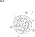
- FIG. 5 shows an example of a carcass cord 2.
- the carcass cord 2 in FIG. 5 has a layer-twisted structure.
- the carcass cord 2 includes a core 4, an intermediate sheath 6, and an outer sheath 8.
- the core 4 is a strand.
- the core 4 is composed of three elemental wires 10 (hereinafter, core wires 10c).
- the intermediate sheath 6 includes 8 elemental wires 10 (hereinafter, intermediate sheath wires 10m).
- the outer sheath 8 includes 13 elemental wires 10 (hereinafter, outer sheath wires 10s).
- the core wires 10c, the intermediate sheath wires 10m, and the outer sheath wires 10s have the same outer diameter.
- the twisting direction of the elemental wires 10 in the core 4 is S-twisting.
- the twisting direction of the elemental wires 10 in the intermediate sheath 6 is S-twisting.
- the twisting direction of the elemental wires 10 in the outer sheath 8 is Z-twisting.
- gaps exist between the adjacent intermediate sheath wires 10m in the intermediate sheath 6. Gaps exist between the adjacent outer sheath wires 10s in the outer sheath 8. Gaps also exist between the core 4 and the intermediate sheath 6 and between the intermediate sheath 6 and the outer sheath 8.
- the carcass cord 2 includes a space therein. Although not shown, the carcass cord 2 is covered with a rubber in the tire. The rubber enters the interior of the carcass cord 2.
- the sum of the intervals between the adjacent outer sheath wires 10s is larger than the outer diameter of the outer sheath wire 10s.
- the carcass cord 2 is also called an open cord.
- a steel cord in which the sum of the intervals between the adjacent outer sheath wires 10s is smaller than the outer diameter of the outer sheath wire 10s is called a close cord.
- rubber is more likely to enter the interior thereof than in a close cord.
- the initial elongation of an open cord is larger than that of a close cord. Therefore, in the case where an open cord is used as each carcass cord, if a groove is provided on each shoulder portion of a tire to decrease the thickness of the shoulder portion, there is a concern that the length of the carcass cord may differ between the portion where the groove is provided and the portion where the groove is not provided. The difference in the length of the carcass cord appears as irregularities (also called undulation) on the surface of the side portion when the tire is inflated. The undulation impairs the appearance quality of the tire.
- An object of the present invention is to provide a tire that can effectively suppress occurrence of undulation with an increase in the mass thereof being minimized, while maintaining a rust-prevention effect of a carcass cord.
- Related technology is known from EP O 744 490 A2 .
- the present invention is set out in the appended claims and directed to a tire including: a pair of beads; a carcass extending on and between a first bead and a second bead out of the pair of beads; and an inner liner located inward of the carcass.
- the carcass includes a carcass ply, and the carcass ply includes a carcass cord.
- the carcass cord is a steel cord.
- the carcass cord includes an outer sheath forming an outer circumferential surface thereof.
- the outer sheath includes a plurality of outer sheath wires.
- the plurality of outer sheath wires are aligned along an outer circumference of the carcass cord, and a sum of intervals between the adjacent outer sheath wires is smaller than an outer diameter of the outer sheath wire.
- the inner liner forms an inner surface of the tire, and an air permeability coefficient of the inner liner is not greater than 12 ⁇ 10 -11 cc ⁇ cm/cm 2 ⁇ sec ⁇ cm Hg.
- the present invention can provide a tire that can effectively suppress occurrence of undulation with an increase in the mass thereof being minimized, while maintaining a rust-prevention effect of a carcass cord.
- the tire of the present invention is fitted on a rim.
- the interior of the tire is filled with air to adjust the internal pressure of the tire.
- the tire fitted on the rim is also referred to as tire-rim assembly.
- the tire-rim assembly includes the rim and the tire fitted on the rim.
- a state where a tire is fitted on a standardized rim, the internal pressure of the tire is adjusted to a standardized internal pressure, and no load is applied to the tire is referred to as a standardized state.
- the dimensions and angles of each component of the tire are measured in the standardized state.
- the dimensions and angles of each component in a meridian cross-section of the tire which cannot be measured in a state where the tire is fitted on the standardized rim, are measured in a cut plane of the tire obtained by cutting the tire along a plane including a rotation axis.
- the tire is set such that the distance between right and left beads is equal to the distance between the beads in the tire that is fitted on the standardized rim.
- the configuration of the tire that cannot be confirmed in a state where the tire is fitted on the standardized rim is confirmed in the above-described cut plane.
- the standardized rim means a rim specified in a standard on which the tire is based.
- the "standard rim” in the JATMA standard, the "Design Rim” in the TRA standard, and the “Measuring Rim” in the ETRTO standard are standardized rims.
- the standardized internal pressure means an internal pressure specified in the standard on which the tire is based.
- the "highest air pressure” in the JATMA standard, the "maximum value” recited in “TIRE LOAD LIMITS AT VARIOUS COLD INFLATION PRESSURES" in the TRA standard, and the “INFLATION PRESSURE” in the ETRTO standard are standardized internal pressures.
- a standardized load means a load specified in the standard on which the tire is based.
- the "maximum load capacity" in the JATMA standard, the “maximum value” recited in the "TIRE LOAD LIMITS AT VARIOUS COLD INFLATION PRESSURES" in the TRA standard, and the “LOAD CAPACITY” in the ETRTO standard are standardized loads.
- a tread portion of the tire is a portion of the tire that comes into contact with a road surface.
- a bead portion is a portion of the tire that is fitted to a rim.
- a sidewall portion is a portion of the tire that extends between the tread portion and the bead portion.
- the tire includes a tread portion, a pair of bead portions, and a pair of sidewall portions as portions thereof.
- a center portion of the tread portion is also referred to as crown portion.
- a portion of the tread portion at an end thereof is also referred to as shoulder portion.
- a boundary portion between the tread portion and each sidewall portion is also referred to as buttress.
- a rubber composition refers to a composition that is obtained by mixing a base rubber and chemicals in a kneading machine such as a Banbury mixer and that contains the uncrosslinked base rubber.
- a crosslinked rubber refers to a crosslinked product, of the rubber composition, obtained by pressurizing and heating the rubber composition.
- the crosslinked rubber contains a crosslinked product of the base rubber.
- the crosslinked rubber is also referred to as vulcanized rubber, and the rubber composition is also referred to as unvulcanized rubber.
- Examples of the base rubber include natural rubber (NR), butadiene rubber (BR), styrene-butadiene rubber (SBR), isoprene rubber (IR), ethylene-propylene rubber (EPDM), chloroprene rubber (CR), acrylonitrile-butadiene rubber (NBR), and isobutylene-isoprene-rubber (IIR).
- Examples of the chemicals include reinforcing agents such as carbon black and silica, plasticizers such as aromatic oil, fillers such as zinc oxide, lubricants such as stearic acid, antioxidants, processing aids, sulfur, and vulcanization accelerators.
- a base rubber and chemicals are determined as appropriate according to the specifications of components, such as a tread and a sidewall, for which the rubber composition is used.
- components such as a tread and a sidewall
- a rubber composition that is generally used in tires is used.
- an air permeability coefficient of a component formed from a crosslinked rubber, of the components of the tire is measured according to the standards of JIS K6275-1.
- the measurement conditions are as follows.
- the air permeability coefficient in the present invention is an air permeability coefficient measured by a differential-pressure method in an environment of 60°C.
- a tire according to one aspect of the present invention includes: a pair of beads; a carcass extending on and between a first bead and a second bead out of the pair of beads; and an inner liner located inward of the carcass, wherein the carcass includes a carcass ply, the carcass ply includes a carcass cord, the carcass cord is a steel cord, the carcass cord includes an outer sheath forming an outer circumferential surface thereof, the outer sheath includes a plurality of outer sheath wires, the plurality of outer sheath wires are aligned along an outer circumference of the carcass cord, a sum of intervals between the adjacent outer sheath wires is smaller than an outer diameter of the outer sheath wire, the inner liner forms an inner surface of the tire, and an air permeability coefficient of the inner liner is not greater than 12 ⁇ 10 -11 cc ⁇ cm/cm 2 ⁇ sec ⁇ cm Hg.
- the length of the carcass cord is less likely to differ over the entire tire. For example, even if a groove is provided on each shoulder portion of the tire so as to extend in a direction along the carcass cord, the length of the carcass cord is less likely to differ between the portion where the groove is provided and the portion where the groove is not provided.
- the tire can effectively suppress occurrence of undulation. It is also unnecessary to take measures such as increasing the thickness of a component such as sidewalls to prevent occurrence of undulation. Since the inner liner has a low air permeability coefficient, the tire can also inhibit rust from forming in the carcass cord. The tire can effectively suppress occurrence of undulation with an increase in the mass thereof being minimized, while maintaining the rust-prevention effect of the carcass cord.
- the carcass cord is covered with a topping rubber, and an entry ratio of the topping rubber in the carcass cord is less than 30%.
- the carcass cord can effectively contribute to suppressing occurrence of undulation.
- a ratio of a cross-sectional height of the tire to a cross-sectional width of the tire is not less than 90%.
- the carcass cord includes an intermediate sheath inside the outer sheath
- the intermediate sheath includes a plurality of intermediate sheath wires
- the plurality of intermediate sheath wires are aligned along the outer sheath
- a twisting direction of the intermediate sheath wires in the intermediate sheath is the same as a twisting direction of the outer sheath wires in the outer sheath.
- the intermediate sheath wires and the outer sheath wires are in sufficient contact with each other as compared to a carcass cord in which the twisting direction of the intermediate sheath wires in the intermediate sheath and the twisting direction of the outer sheath wires in the outer sheath are opposite to each other. Since the strength of the carcass cord is increased as a whole, the tire can suppress occurrence of sidewall concussion. Moreover, since the internal space of the carcass cord is further reduced, this carcass cord can more effectively contribute to suppressing occurrence of undulation. Since the inner liner has a low air permeability coefficient, even if this carcass cord is used, rust is sufficiently inhibited from forming in the carcass cord. The tire can effectively suppress occurrence of undulation with an increase in the mass thereof being minimized, while maintaining the rust-prevention effect of the carcass cord.
- the carcass cord includes a core at a center of the carcass cord, the intermediate sheath is located between the core and the outer sheath, the core is composed of one core wire, a number of the intermediate sheath wires included in the intermediate sheath is 6, a number of the outer sheath wires included in the outer sheath is 12, and the core wire, the intermediate sheath wires, and the outer sheath wires have the same outer diameter.
- the elemental wires included in the carcass cord are more compactly bundled, and a carcass cord having a smaller internal space is formed.
- This carcass cord can effectively contribute to suppressing occurrence of undulation. Since the inner liner has a low air permeability coefficient, even if this carcass cord is used, rust is sufficiently inhibited from forming in the carcass cord. The tire can effectively suppress occurrence of undulation with an increase in the mass thereof being minimized, while maintaining the rust-prevention effect of the carcass cord.
- a thickness of a rubber component located between the carcass cord and the inner surface of the tire is not less than 4.5 mm.
- FIG. 1 shows a part of a cross-section (hereinafter, meridian cross-section) of the tire 22 taken along a plane including the rotation axis of the tire 22.
- the right-left direction is the axial direction of the tire 22
- the up-down direction is the radial direction of the tire 22.
- the direction perpendicular to the surface of the drawing sheet of FIG. 1 is the circumferential direction of the tire 22.
- an alternate long and short dash line CL extending in the radial direction represents the equator plane of the tire 22.
- a solid line BBL extending in the axial direction is a bead base line.
- the bead base line BBL is a line that defines the rim diameter (see JATMA or the like) of the rim R.
- the tire 22 includes a tread 24, a pair of sidewalls 26, a pair of chafers 28, a pair of beads 30, a carcass 32, a belt 34, a pair of cushion layers 36, a pair of steel reinforcing layers 38, a pair of interlayer strips 40, an inner liner 42, and an insulation 44.
- the tread 24 is located radially outward of the carcass 32.
- the tread 24 comes into contact with a road surface at a tread surface 46 thereof.
- Grooves 48 are formed on the tread 24.
- the tread 24 is formed from a crosslinked rubber.
- a position indicated by reference character PC is an equator.
- the equator PC is the point of intersection of the tread surface 46 and the equator plane CL.
- the equator PC is specified on the basis of a virtual tread surface obtained on the assumption that the groove 48 is not provided thereon.
- the distance in the radial direction from the bead base line BBL to the equator PC, obtained in the tire 22 in the standardized state, is the cross-sectional height (see JATMA or the like) of the tire 22.
- Each sidewall 26 is connected to an end of the tread 24.
- the sidewall 26 is located radially inward of the tread 24.
- the sidewall 26 is located axially outward of the carcass 32.
- the sidewall 26 is formed from a crosslinked rubber.
- a position indicated by reference character PW is an axially outer end (hereinafter, outer end PW) of the tire 22.
- outer end PW is specified on the basis of a virtual outer surface obtained on the assumption that the decorations are not present thereon.
- the tire 22 has a maximum width at the outer end PW.
- the outer end PW is also referred to as maximum width position.
- the distance in the axial direction from a first outer end PW to a second outer end PW (not shown), obtained in the tire 22 in the standardized state, is the cross-sectional width (see JATMA or the like) of the tire 22.
- the ratio of the cross-sectional height of the tire 22 to the cross-sectional width of the tire 22 is not less than 90%.
- Each chafer 28 is located radially inward of the sidewall 26.
- the chafer 28 comes into contact with the rim R.
- the chafer 28 is formed from a crosslinked rubber.
- Each bead 30 is located axially inward of the chafer 28.
- the bead 30 is located radially inward of the sidewall 26.
- the bead 30 includes a bead core 50 and an apex 52.
- the bead core 50 extends in the circumferential direction. Although not shown, the bead core 50 includes a wire made of steel and wound in the circumferential direction.
- the apex 52 is located radially outward of the bead core 50.
- the apex 52 extends radially outward from the bead core 50.
- the apex 52 is tapered outward.
- the apex 52 is formed from a hard crosslinked rubber.
- the carcass 32 is located inward of the tread 24, the pair of sidewalls 26, and the pair of chafers 28.
- the carcass 32 extends on and between the pair of beads 30, that is, a first bead 30 and a second bead 30 (not shown) out of the pair of beads 30.
- the carcass 32 of the tire 22 has a radial structure.
- the carcass 32 includes at least one carcass ply 54.
- the carcass 32 of the tire 22 is composed of one carcass ply 54.
- the carcass ply 54 is turned up at each bead 30.
- the carcass ply 54 includes a ply body 56 and a pair of turned-up portions 58.
- the ply body 56 extends between the pair of beads 30.
- Each turned-up portion 58 is connected to the ply body 56 and turned up at the bead 30.
- Each turned-up portion 58 of the tire 22 is turned up from the inner side toward the outer side in the axial direction at the bead 30.
- An end of the turned-up portion 58 is located radially inward of an outer end of the apex 52.
- the belt 34 is located between the tread 24 and the carcass 32 in the radial direction.
- the belt 34 of the tire 22 is stacked on the carcass 32.
- the belt 34 includes a plurality of belt plies 60 aligned in the radial direction.
- the belt 34 of the tire 22 includes four belt plies 60.
- the four belt plies 60 are a first belt ply 60A, a second belt ply 60B, a third belt ply 60C, and a fourth belt ply 60D.
- the first belt ply 60A is located on the innermost side in the radial direction.
- Each cushion layer 36 is located between the belt 34 and the carcass 32 at an end of the belt 34.
- the cushion layer 36 is formed from a flexible crosslinked rubber.
- Each steel reinforcing layer 38 is located in a bead portion B.
- the steel reinforcing layer 38 is located between the chafer 28 and the carcass 32.
- the steel reinforcing layer 38 is turned up at the bead 30.
- the steel reinforcing layer 38 is placed so as to wrap a radially inner portion of the bead 30 from the radially inner side of the turned-up portion 58.
- the entire steel reinforcing layer 38 is located radially inward of the end of the turned-up portion 58.
- the steel reinforcing layer 38 includes a large number of filler cords aligned with each other, which are not shown. These filler cords are covered with a topping rubber. Each filler cord is tilted relative to the radial direction. A steel cord is used as each filler cord of the tire 22.
- the inner liner 42 is located inward of the carcass 32.
- the inner liner 42 forms an inner surface of the tire 22.
- the inner liner 42 is formed from a crosslinked rubber that has an excellent air blocking property. From the viewpoint that the inner liner 42 can have a property of being less permeable to air, the rubber composition for the inner liner 42 preferably contains a butyl-based rubber as a base rubber.
- the base rubber of the rubber composition for the inner liner 42 can also contain a rubber component other than the butyl-based rubber.
- the rubber component other than the butyl-based rubber is, for example, natural rubber.
- the content of the butyl-based rubber contained in the base rubber of the rubber composition is preferably not less than 80% by mass and not greater than 100% by mass, and more preferably not less than 85% by mass and not greater than 100% by mass.
- the rubber composition for the inner liner 42 can contain the above-described chemicals such as carbon black and fillers.
- the rubber composition for the inner liner 42 may be subjected to degassing treatment.
- the degassing treatment is, for example, degassing treatment, using a bent extruder, described in Japanese Patent No. 6438437 .
- the insulation 44 is located between the inner liner 42 and the carcass 32.
- the insulation 44 is formed from a crosslinked rubber that has excellent adhesiveness.
- the insulation 44 is jointed to the carcass 32 and also to the inner liner 42.
- the inner liner 42 of the tire 22 is joined to the inner surface of the carcass 32 via the insulation 44.
- FIG. 2 shows a cross-section along a line II-II in FIG. 1 .
- the line II-II passes through the maximum width position PW and extends in the axial direction.
- FIG. 2 shows a cross-section of the tire 22 at the maximum width position PW.
- the carcass ply 54 of the tire 22 includes a large number of carcass cords 62 aligned with each other. These carcass cords 62 are covered with a topping rubber 64. Although not shown, each carcass cord 62 intersects the equator plane CL. Each carcass cord 62 of the tire 22 is a steel cord.
- the outer sheath 68 includes a plurality of elemental wires 66.
- the elemental wires 66 included in the outer sheath 68 are also referred to as outer sheath wires 66s.
- the plurality of outer sheath wires 66s are aligned along the outer circumference of the carcass cord 62.
- the outer sheath 68 includes the plurality of outer sheath wires 66s, and the plurality of outer sheath wires 66s are aligned along the outer circumference of the carcass cord 62.
- the plurality of outer sheath wires 66s are closely aligned in the outer sheath 68. There are no gaps between the adjacent outer sheath wires 66s, but even if there are gaps therebetween, the size of each of the gaps is such that the sum of all the gaps in the outer sheath 68 does not allow an outer sheath wire 66s to be further added to the outer sheath 68.
- the distance, between two outer sheath wires 66s, measured along a straight line connecting the centers of the adjacent outer sheath wires 66s, is defined as an interval between the adjacent outer sheath wires 66s
- the sum of the intervals between the adjacent outer sheath wires 66s is smaller than the outer diameter of the outer sheath wire 66s.
- the carcass cord 62 is a close cord. The initial elongation of the carcass cord 62 is smaller than that of a carcass cord that is an open cord. Therefore, the length of the carcass cord 62 is less likely to differ over the entire tire 22.
- the length of the carcass cord 62 is less likely to differ between the portion where the groove is provided and the portion where the groove is not provided.
- the tire 22 can effectively suppress occurrence of undulation.
- the internal space of the close cord is narrower than the internal space of the open cord.
- the plurality of outer sheath wires 66s included in the outer sheath 68 are closely aligned. Therefore, rubber is less likely to enter into the interior of the carcass cord 62, which is a close cord, than into the interior of the open cord. Therefore, there is a concern that water contained in the air with which the interior of the tire 22 is filled may accumulate inside the carcass cord 62, causing rust to form in the carcass cord 62.
- the inner liner 42 of the tire 22 is formed from a crosslinked rubber that is less permeable to air.
- the air permeability coefficient of the inner liner 42 is not greater than 12 ⁇ 10 -11 cc ⁇ cm/cm 2 ⁇ sec ⁇ cm Hg.
- the inner liner 42 suppresses entry of moisture into the interior of the tire 22. Water is less likely to accumulate inside each carcass cord 62 of the tire 22.
- the tire 22 can inhibit rust from forming in the carcass cord 62.
- the tire 22 can effectively suppress occurrence of undulation with an increase in the mass thereof being minimized, while maintaining the rust-prevention effect of the carcass cord 62.
- the air permeability coefficient of the inner liner 42 is not greater than 12 ⁇ 10 -11 cc ⁇ cm/cm 2 ⁇ sec ⁇ cm Hg. From the viewpoint of being able to improve the rust-prevention effect of the carcass cord 62, the air permeability coefficient of the inner liner 42 is preferably not greater than 9.5 ⁇ 10 -11 cc ⁇ cm/cm 2 ⁇ sec ⁇ cm Hg.
- each carcass cord 62 is a close cord, and the internal space of the close cord is narrower than the internal space of the open cord. Therefore, rubber is less likely to enter into the interior of the carcass cord 62 than into the interior of the open cord.
- an entry ratio of the topping rubber in the carcass cord is obtained as follows.
- a carcass cord having a length of about 10 cm (hereinafter, referred to as rubberized cord) is taken out from the tire in a state where the topping rubber adheres thereto.
- a knife is inserted through the cross-section of the cord, and two adjacent elemental wires out of the elemental wires of the outer sheath are removed.
- a portion where the gap formed between the removed two elemental wires and the intermediate sheath is completely filled with rubber is confirmed, and the length of this portion is measured.
- the ratio of the length of the portion filled with rubber to the entire length (hereinafter, also referred to as rubber entry ratio) is calculated.
- 10 rubberized cords are taken out from the tire, and the rubber entry ratio is obtained for each of the rubberized cords.
- the average of the 10 rubber entry ratios is used as an entry ratio of the topping rubber in the carcass cord.
- the entry ratio of the topping rubber 64 in the carcass cord 62 is less than 30%.
- the internal space of the carcass cord 62 is much narrower than that of the open cord.
- the narrow internal space contributes to a reduction in the initial elongation of the carcass cord 62.
- the carcass cord 62 can effectively contribute to suppressing occurrence of undulation. From this viewpoint, the entry ratio is preferably not greater than 25%.
- the carcass cord 62 includes an intermediate sheath 70 inside the outer sheath 68.
- the intermediate sheath 70 of the carcass cord 62 shown in FIG. 3 includes 6 intermediate sheath wires 66m.
- the number of intermediate sheath wires 66m included in the intermediate sheath 70 may be 5 or less, or may be 7 or more.
- the number of intermediate sheath wires 66m included in the intermediate sheath 70 is determined as appropriate according to the characteristics required for the carcass cord 62.
- the plurality of intermediate sheath wires 66m are aligned along the outer sheath 68 of the carcass cord 62.
- the intermediate sheath 70 includes the plurality of intermediate sheath wires 66m, and the plurality of intermediate sheath wires 66m are aligned along the outer sheath 68.
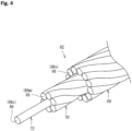
- FIG. 4 shows a part of the carcass cord 62 shown in FIG. 3 .
- the plurality of outer sheath wires 66s included in the outer sheath 68 are twisted in a predetermined direction.
- the plurality of intermediate sheath wires 66m included in the intermediate sheath 70 are also twisted in a predetermined direction.
- the twisting direction of the intermediate sheath wires 66m in the intermediate sheath 70 is the same as the twisting direction of the outer sheath wires 66s in the outer sheath 68. Accordingly, the elemental wires 66 included in the carcass cord 62 are more compactly bundled. In the carcass cord 62, the intermediate sheath wires 66m and the outer sheath wires 66s are in sufficient contact with each other as compared to a carcass cord in which the twisting direction of the intermediate sheath wires 66m in the intermediate sheath 70 is opposite to the twisting direction of the outer sheath wires 66s in the outer sheath 68.
- the contact area between the adjacent elemental wires increases, and the elemental wires can support each other, so that the strength of the carcass cord 62 is increased as a whole. Occurrence of break of the carcass cord in each side portion of the tire 22 (also referred to as sidewall concussion) is suppressed. Moreover, since the internal space of the carcass cord 62 is further reduced, the carcass cord 62 has a smaller initial elongation. The carcass cord 62 can more effectively contribute to suppressing occurrence of undulation.
- the inner liner 42 having a low air permeability coefficient effectively suppresses entry of moisture into the interior of the tire 22, even when the carcass cord 62 in which the elemental wires 66 are compactly bundled is used, rust is sufficiently inhibited from forming in the carcass cord 62.
- the tire 22 can effectively suppress occurrence of undulation with an increase in the mass thereof being minimized, while maintaining the rust-prevention effect of the carcass cord 62.
- the carcass cord 62 includes the intermediate sheath 70 inside the outer sheath 68
- the intermediate sheath 70 includes the plurality of intermediate sheath wires 66m
- the plurality of intermediate sheath wires 66m are aligned along the outer sheath 68
- the twisting direction of the intermediate sheath wires 66m in the intermediate sheath 70 is the same as the twisting direction of the outer sheath wires 66s in the outer sheath 68.
- one intermediate sheath 70 is provided between the core 72 and the outer sheath 68, but a plurality of intermediate sheaths may be provided between the core 72 and the outer sheath 68 so as to be aligned in the radial direction of the carcass cord 62.
- the core 72 may be a strand including two or more core wires 66c.
- the strand is formed by twisting together the two or more core wires 66c.
- the core 72 is preferably composed of one core wire 66c. Accordingly, the elemental wires 66 included in the carcass cord 62 are more compactly bundled, and a carcass cord 62 having a smaller internal space is formed. This carcass cord 62 can effectively contribute to suppressing occurrence of undulation.
- the carcass cord 62 includes the core 72, the intermediate sheath 70, and the outer sheath 68.
- the core 72 is composed of the one core wire 66c, the number of intermediate sheath wires 66m included in the intermediate sheath 70 is 6, and the number of outer sheath wires 66s included in the outer sheath 68 is 12.
- the core wire 66c, the intermediate sheath wires 66m, and the outer sheath wires 66s have the same outer diameter.
- the cord structure of the carcass cord 62 is represented by "1 + 6 + 12".
- the elemental wires 66 included in the carcass cord 62 are more compactly bundled, and a carcass cord 62 having a smaller internal space is formed.
- the carcass cord 62 can more effectively contribute to suppressing occurrence of undulation.
- the core 72 is composed of the one core wire 66c
- the number of intermediate sheath wires 66m included in the intermediate sheath 70 is 6
- the number of outer sheath wires 66s included in the outer sheath 68 is 12, and the core wire 66c, the intermediate sheath wires 66m, and the outer sheath wires 66s have the same outer diameter.
- the cross-section of the tire 22 shown in FIG. 2 is the cross-section of the tire 22 at the maximum width position PW. Therefore, the thickness T of the rubber component shown in FIG. 2 is the thickness of the rubber component, located between the carcass cord 62 and the inner surface of the tire 22, at the maximum width position PW.
- the thickness T of the rubber component located between the carcass cord 62 and the inner surface of the tire 22 is preferably not less than 4.5 mm. Accordingly, the moisture existing in the space between the tire 22 and the rim R is inhibited from permeating into the interior of the tire 22. Since the opportunity for the carcass cord 62 to come into contact with moisture is reduced, rust is inhibited from forming in the carcass cord 62.
- the rubber component located between the carcass cord 62 and the inner surface of the tire 22 can effectively contribute to improving the rust-prevention effect of the carcass cord 62. Since the carcass cord 62 is less likely to rust, the properties of the carcass cord 62 are stably maintained.
- the tire 22 can also improve sidewall concussion resistance.
- the thickness T of the rubber component is preferably not greater than 6.0 mm.
- a length indicated by a double-headed arrow TI is the thickness of the inner liner 42 at the maximum width position PW.
- the ratio (TI/T) of the thickness TI of the inner liner 42 to the thickness T of the rubber component is preferably not less than 0.3. From the viewpoint of being able to suppress the influence of the inner liner 42 on the mass of the tire 22, the ratio (TI/T) is preferably not greater than 0.5.
- the present invention a tire that can suppress occurrence of undulation without increasing the mass thereof, while maintaining a rust-prevention effect of a carcass cord, is obtained.
- the tire to which the present invention is applicable is not particularly limited as long as a steel cord is used as each carcass cord.
- the tire to which the present invention is applicable may be, for example, a tire for a passenger car, or a tire for a small truck.
- the present invention exhibits a remarkable effect in the case where the ratio of the cross-sectional height of the tire 22 to the cross-sectional width of the tire 22 in the standardized state is not less than 90%.
- the steel cord (close cord) shown in FIG. 3 was used as each carcass cord.
- the structure of this carcass cord was "1 ⁇ 0.25 + 6 + 12 ⁇ 0.225".
- the inner liner was formed using a rubber composition subjected to degassing treatment.
- the air permeability coefficient of the inner liner was 9.5 ⁇ 10 -11 cc ⁇ cm/cm 2 ⁇ sec ⁇ cm Hg. This is represented as "L” in the cell for "Inner liner” in Table 1 below.
- the thickness T of the rubber component at the maximum width position was set to 4.5 mm.
- a tire of Comparative Example 1 was obtained in the same manner as Example 1, except that the carcass cord, the inner liner, and the thickness T of the rubber component were set as shown in Table 1 below.
- the steel cord (open cord) shown in FIG. 5 was used as each carcass cord.
- the structure of this carcass cord was "3 + 8 + 13 ⁇ 0.23".
- twisting direction of the core wires in the core and the twisting direction of the intermediate sheath wires in the intermediate sheath were "S-twisting", and the twisting direction of the outer sheath wires in the outer sheath was "Z-twisting".
- the inner liner was formed using a rubber composition that had not been subjected to degassing treatment.
- the configuration of the rubber composition used for forming the inner liner is the same as that of the rubber composition used in Example 1.
- the air permeability coefficient of the inner liner was 15 ⁇ 10 -11 cc ⁇ cm/cm 2 ⁇ sec ⁇ cm Hg. This is represented as "H" in the cell for "Inner liner” in Table 1 below.
- the thickness T of the rubber component at the maximum width position was set to 4.0 mm by adjusting the thickness TI of the inner liner.
- the tire was caused to run on a drum having a radius of 1.7 m at a speed of 80 km/h. After running a predetermined distance, the tire was dismantled and checked for the state of formation of rust in the carcass cord.
- the results are represented in Table 1 below as an index with the result of Comparative Example 1 being regarded as 100. The higher the value is, the more the formation of rust was suppressed.
- the tire was mounted to a drum type tire testing machine, and a vertical load of 39.23 kN was applied to the tire.
- the tire was caused to run on a drum having a radius of 1.7 m at a speed of 80 km/h. After running a predetermined distance, the surface of the tire was observed to check the state of occurrence of undulation.
- the results are represented in Table 1 below as an index with the result of Comparative Example 1 being regarded as 100. The higher the value is, the more the occurrence of undulation is suppressed.
- a weight having a blade was dropped toward the buttress of the tire while changing the height position of the weight, until the carcass cord was broken, and the height at which the carcass cord was broken was obtained.
- the fracture energy was calculated on the basis of this height.
- Table 1 below as an index with the result of Comparative Example 1 being regarded as 100. The higher the value is, the better the sidewall concussion resistance is.
- the mass of the weight was 33 kg.
- the length of the blade was 3 cm.
- Example 1 As shown in Table 1, in Example 1, the occurrence of undulation is suppressed without increasing the mass, while increasing the rust-prevention effect of the carcass cord. From the evaluation results, advantages of the present invention are clear.
- the above-described technology capable of suppressing occurrence of undulation without increasing the mass, while maintaining a rust-prevention effect of a carcass cord, can be applied to various tires.
Landscapes
- Engineering & Computer Science (AREA)
- Mechanical Engineering (AREA)
- Tires In General (AREA)
- Ropes Or Cables (AREA)
Claims (4)
- Reifen (22), umfassend:ein Paar Wülste (30);eine Karkasse (32), die sich auf und zwischen einem ersten Wulst (30) und einem zweiten Wulst (30) aus dem Paar Wülste (30) erstreckt; undeinen Innerliner (42), der innen non der Karkasse (32) angeordnet ist, wobeidie Karkasse (32) eine Karkasslage (54) umfasst,die Karkasslage (54) einen Karkasskord (62) umfasst,der Karkasskord (62) ein Stahlkord ist,der Karkasskord (62) eine äußere Ummantelung (68) umfasst, die eine äußere Umfangsoberfläche davon bildet,die äußere Ummantelung (68) eine Vielzahl von äußeren Ummantelungsdrähten (66s) umfasst,die Vielzahl von äußeren Ummantelungsdrähten (66s) entlang eines äußeren Umfangs des Karkasskords (62) ausgerichtet sind,eine Summe von Intervallen zwischen den benachbarten äußeren Ummantelungsdrähten (66s) kleiner als ein Außendurchmesser des äußeren Ummantelungsdrahts (66s) ist, wobei ein Intervall zwischen zwei benachbarten äußeren Ummantelungsdrähten (66s) als der Abstand zwischen den zwei äußeren Ummantelungsdrähten (66s), gemessen entlang einer geraden Linie, die die Mitten der zwei benachbarten äußeren Ummantelungsdrähte (66s) verbindet, definiert ist,der Innerliner (42) eine innere Oberfläche des Reifens (22) bildet, dadurch gekennzeichnet, dassein Luftdurchlässigkeitskoeffizient des Innerliners (42) nicht größer als 12 × 10-11 cc·cm/cm2·s·cm Hg ist, wobei der Luftdurchlässigkeitskoeffizient gemäß den Standards von JIS K6275-1 mit den folgenden Messbedingungen gemessen wird: gemessen durch ein Differenzdruckverfahren in einer Umgebung von 60 °C unter Verwendung einer Gasdurchlässigkeitsmessvorrichtung "G2700", hergestellt von Yanaco Analytical Systems Inc., mit Luft als Testgas bei einer Testtemperatur von 60 °C,der Karkasskord (62) einen Kern (72) in einer Mitte des Karkasskords (62) und eine Zwischenummantelung (70), die zwischen dem Kern (72) und der äußeren Ummantelung (68) angeordnet ist, umfasst, wobeider Kern (72) aus einem Kerndraht (66c) zusammengesetzt ist,eine Anzahl der Zwischenummantelungsdrähte (66m), die in der Zwischenummantelung (70) enthalten sind, 6 beträgt,eine Anzahl der äußeren Ummantelungsdrähte (66s), die in der äu-βeren Ummantelung (68) enthalten sind, 12 beträgt, undder Kerndraht (66c), die Zwischenummantelungsdrähte (66m) und die äußeren Ummantelungsdrähte (66s) den gleichen Außendurchmesser aufweisen,die Vielzahl von Zwischenummantelungsdrähten (66m) entlang der äußeren Ummantelung (68) ausgerichtet sind, undeine Verdrillungsrichtung der Zwischenummantelungsdrähte (66m) in der Zwischenummantelung (70) die gleiche wie eine Verdrillungsrichtung der äußeren Ummantelungsdrähte (66s) in der äußeren Ummantelung (68) ist.
- Reifen (22) nach Anspruch 1, wobeider Karkasskord (62) mit einem Deckgummi (64) bedeckt ist, undein Eintrittsverhältnis des Deckgummis (64) in den Karkasskord (62) weniger als 30 % beträgt,wobei das Eintrittsverhältnis des Deckgummis (64) in den Karkasskord (62) wie folgt erhalten wird: ein Karkasskord (62) mit einer Länge von etwa 10 cm wird aus dem Reifen in einem Zustand herausgenommen, in dem der Deckgummi (64) daran haftet; nach dem Entfernen von so viel Gummi wie möglich von der Oberfläche des Karkasskords (62) wird ein Messer durch den Querschnitt des Karkasskords (62) eingeführt, und zwei benachbarte äußere Ummantelungsdrähte (66s) der äußeren Ummantelung (68) werden entfernt; ein Abschnitt, in dem der Spalt, der zwischen den entfernten zwei äußeren Ummantelungsdrähten (66s) und der Zwischenummantelung (70) gebildet ist, vollständig mit Gummi gefüllt ist, wird bestätigt, und die Länge dieses Abschnitts wird gemessen; das Verhältnis der Länge des Abschnitts, der mit Gummi gefüllt ist, zu der gesamten Länge wird als ein Gummieintrittsverhältnis berechnet; 10 Karkasskorde (62) mit einer Länge von etwa 10 cm werden aus dem Reifen herausgenommen, und ein Gummieintrittsverhältnis wird für jeden der 10 herausgenommenen Karkasskorde (62) erhalten, und der Durchschnitt der 10 Gummieintrittsverhältnisse wird als das Eintrittsverhältnis des Deckgummis (64) in den Karkasskord (62) verwendet.
- Reifen (22) nach Anspruch 1 oder 2, wobei in einem Zustand, in dem der Reifen (22) auf eine standardisierte Felge (R) aufgezogen ist, ein Innendruck des Reifens (22) auf einen standardisierten Innendruck eingestellt wird, und keine Last auf den Reifen (22) ausgeübt wird,
ein Verhältnis einer Querschnittshöhe des Reifens (22) zu einer Querschnittsbreite des Reifens (22) nicht weniger als 90 % beträgt. - Reifen (22) nach einem der Ansprüche 1 bis 3, wobei eine Dicke (T) einer Gummikomponente, die zwischen dem Karkasskord (62) und der inneren Oberfläche des Reifens (22) angeordnet ist, nicht weniger als 4,5 mm beträgt.
Applications Claiming Priority (1)
| Application Number | Priority Date | Filing Date | Title |
|---|---|---|---|
| JP2022200222A JP2024085616A (ja) | 2022-12-15 | 2022-12-15 | タイヤ |
Publications (2)
| Publication Number | Publication Date |
|---|---|
| EP4385759A1 EP4385759A1 (de) | 2024-06-19 |
| EP4385759B1 true EP4385759B1 (de) | 2025-02-26 |
Family
ID=89073232
Family Applications (1)
| Application Number | Title | Priority Date | Filing Date |
|---|---|---|---|
| EP23213584.8A Active EP4385759B1 (de) | 2022-12-15 | 2023-12-01 | Reifen |
Country Status (2)
| Country | Link |
|---|---|
| EP (1) | EP4385759B1 (de) |
| JP (1) | JP2024085616A (de) |
Family Cites Families (10)
| Publication number | Priority date | Publication date | Assignee | Title |
|---|---|---|---|---|
| US5806296A (en) * | 1995-05-26 | 1998-09-15 | Bridgestone Metalpha Corporation | Corrosion resistant spiral steel filament and steel cord made therefrom |
| DE69737185T2 (de) * | 1996-05-29 | 2007-11-08 | The Yokohama Rubber Co., Ltd. | Verfahren zur herstellung eines luftreifen unter verwendung einer niedrigpermeablen thermoplastischen elastomerzusammensetzung in einer gassperrschicht |
| JPWO2005007423A1 (ja) * | 2003-07-17 | 2006-08-31 | 横浜ゴム株式会社 | 耐久性の改良された空気入りタイヤ |
| JP4990575B2 (ja) * | 2006-07-24 | 2012-08-01 | 株式会社ブリヂストン | 空気入りタイヤ用インナーライナー及びそれを備えた空気入りタイヤ |
| JP4340314B2 (ja) | 2007-11-27 | 2009-10-07 | 住友ゴム工業株式会社 | 空気入りタイヤ |
| US20120103487A1 (en) * | 2010-10-28 | 2012-05-03 | Ramendra Nath Majumdar | Pneumatic tire with tire layer and dva barrier layer adhered thereto and method of making same |
| JP2016196220A (ja) * | 2015-04-02 | 2016-11-24 | 横浜ゴム株式会社 | 空気入りタイヤ |
| JP6438437B2 (ja) | 2016-05-23 | 2018-12-12 | 住友ゴム工業株式会社 | 空気入りタイヤ |
| JP2020037330A (ja) * | 2018-09-04 | 2020-03-12 | 株式会社ブリヂストン | 空気入りタイヤ |
| CN112779797A (zh) * | 2021-01-15 | 2021-05-11 | 江苏兴达钢帘线股份有限公司 | 一种紧密型钢帘线 |
-
2022
- 2022-12-15 JP JP2022200222A patent/JP2024085616A/ja active Pending
-
2023
- 2023-12-01 EP EP23213584.8A patent/EP4385759B1/de active Active
Also Published As
| Publication number | Publication date |
|---|---|
| EP4385759A1 (de) | 2024-06-19 |
| JP2024085616A (ja) | 2024-06-27 |
Similar Documents
| Publication | Publication Date | Title |
|---|---|---|
| EP2676808B1 (de) | Luftreifen | |
| EP4019279B1 (de) | Reifen | |
| EP2818332B1 (de) | Luftreifen | |
| EP3202594B1 (de) | Luftreifen | |
| EP3885167B1 (de) | Reifen | |
| EP3281805B1 (de) | Luftreifen | |
| EP3231634B1 (de) | Luftreifen | |
| EP3594019B1 (de) | Schwerlastluftreifen | |
| EP4180241B1 (de) | Schwerlastluftreifen | |
| US11820173B2 (en) | Pneumatic tire and pneumatic tire manufacturing method | |
| EP4019281B1 (de) | Reifen | |
| EP4067115A1 (de) | Reifen | |
| EP4019280B1 (de) | Reifen | |
| EP4385759B1 (de) | Reifen | |
| EP4140771B1 (de) | Reifen | |
| US12344045B2 (en) | Tire | |
| EP4059740B1 (de) | Reifen | |
| US20230014133A1 (en) | Heavy duty tire | |
| EP4296088B1 (de) | Reifen | |
| EP4321351A2 (de) | Reifen | |
| EP4574459A1 (de) | Reifen | |
| EP4140772B1 (de) | Reifen | |
| JP6063302B2 (ja) | 空気入りタイヤ | |
| EP4257372A1 (de) | Reifen | |
| EP3228476B1 (de) | Luftreifen |
Legal Events
| Date | Code | Title | Description |
|---|---|---|---|
| PUAI | Public reference made under article 153(3) epc to a published international application that has entered the european phase |
Free format text: ORIGINAL CODE: 0009012 |
|
| STAA | Information on the status of an ep patent application or granted ep patent |
Free format text: STATUS: THE APPLICATION HAS BEEN PUBLISHED |
|
| AK | Designated contracting states |
Kind code of ref document: A1 Designated state(s): AL AT BE BG CH CY CZ DE DK EE ES FI FR GB GR HR HU IE IS IT LI LT LU LV MC ME MK MT NL NO PL PT RO RS SE SI SK SM TR |
|
| STAA | Information on the status of an ep patent application or granted ep patent |
Free format text: STATUS: REQUEST FOR EXAMINATION WAS MADE |
|
| 17P | Request for examination filed |
Effective date: 20241031 |
|
| RBV | Designated contracting states (corrected) |
Designated state(s): AL AT BE BG CH CY CZ DE DK EE ES FI FR GB GR HR HU IE IS IT LI LT LU LV MC ME MK MT NL NO PL PT RO RS SE SI SK SM TR |
|
| GRAP | Despatch of communication of intention to grant a patent |
Free format text: ORIGINAL CODE: EPIDOSNIGR1 |
|
| STAA | Information on the status of an ep patent application or granted ep patent |
Free format text: STATUS: GRANT OF PATENT IS INTENDED |
|
| RIC1 | Information provided on ipc code assigned before grant |
Ipc: B60C 9/04 20060101ALI20241129BHEP Ipc: B60C 11/00 20060101ALI20241129BHEP Ipc: B60C 9/00 20060101ALI20241129BHEP Ipc: B60C 9/02 20060101ALI20241129BHEP Ipc: B60C 3/04 20060101ALI20241129BHEP Ipc: B60C 5/14 20060101AFI20241129BHEP |
|
| INTG | Intention to grant announced |
Effective date: 20241212 |
|
| GRAS | Grant fee paid |
Free format text: ORIGINAL CODE: EPIDOSNIGR3 |
|
| GRAA | (expected) grant |
Free format text: ORIGINAL CODE: 0009210 |
|
| STAA | Information on the status of an ep patent application or granted ep patent |
Free format text: STATUS: THE PATENT HAS BEEN GRANTED |
|
| AK | Designated contracting states |
Kind code of ref document: B1 Designated state(s): AL AT BE BG CH CY CZ DE DK EE ES FI FR GB GR HR HU IE IS IT LI LT LU LV MC ME MK MT NL NO PL PT RO RS SE SI SK SM TR |
|
| REG | Reference to a national code |
Ref country code: GB Ref legal event code: FG4D |
|
| REG | Reference to a national code |
Ref country code: CH Ref legal event code: EP |
|
| REG | Reference to a national code |
Ref country code: DE Ref legal event code: R096 Ref document number: 602023002216 Country of ref document: DE |
|
| REG | Reference to a national code |
Ref country code: IE Ref legal event code: FG4D |
|
| P01 | Opt-out of the competence of the unified patent court (upc) registered |
Free format text: CASE NUMBER: APP_12374/2025 Effective date: 20250313 |
|
| REG | Reference to a national code |
Ref country code: NL Ref legal event code: MP Effective date: 20250226 |
|
| PG25 | Lapsed in a contracting state [announced via postgrant information from national office to epo] |
Ref country code: RS Free format text: LAPSE BECAUSE OF FAILURE TO SUBMIT A TRANSLATION OF THE DESCRIPTION OR TO PAY THE FEE WITHIN THE PRESCRIBED TIME-LIMIT Effective date: 20250526 |
|
| PG25 | Lapsed in a contracting state [announced via postgrant information from national office to epo] |
Ref country code: FI Free format text: LAPSE BECAUSE OF FAILURE TO SUBMIT A TRANSLATION OF THE DESCRIPTION OR TO PAY THE FEE WITHIN THE PRESCRIBED TIME-LIMIT Effective date: 20250226 |
|
| PG25 | Lapsed in a contracting state [announced via postgrant information from national office to epo] |
Ref country code: PL Free format text: LAPSE BECAUSE OF FAILURE TO SUBMIT A TRANSLATION OF THE DESCRIPTION OR TO PAY THE FEE WITHIN THE PRESCRIBED TIME-LIMIT Effective date: 20250226 |
|
| PG25 | Lapsed in a contracting state [announced via postgrant information from national office to epo] |
Ref country code: ES Free format text: LAPSE BECAUSE OF FAILURE TO SUBMIT A TRANSLATION OF THE DESCRIPTION OR TO PAY THE FEE WITHIN THE PRESCRIBED TIME-LIMIT Effective date: 20250226 |
|
| REG | Reference to a national code |
Ref country code: LT Ref legal event code: MG9D |
|
| PG25 | Lapsed in a contracting state [announced via postgrant information from national office to epo] |
Ref country code: IS Free format text: LAPSE BECAUSE OF FAILURE TO SUBMIT A TRANSLATION OF THE DESCRIPTION OR TO PAY THE FEE WITHIN THE PRESCRIBED TIME-LIMIT Effective date: 20250626 Ref country code: NO Free format text: LAPSE BECAUSE OF FAILURE TO SUBMIT A TRANSLATION OF THE DESCRIPTION OR TO PAY THE FEE WITHIN THE PRESCRIBED TIME-LIMIT Effective date: 20250526 |
|
| PG25 | Lapsed in a contracting state [announced via postgrant information from national office to epo] |
Ref country code: NL Free format text: LAPSE BECAUSE OF FAILURE TO SUBMIT A TRANSLATION OF THE DESCRIPTION OR TO PAY THE FEE WITHIN THE PRESCRIBED TIME-LIMIT Effective date: 20250226 |
|
| PG25 | Lapsed in a contracting state [announced via postgrant information from national office to epo] |
Ref country code: HR Free format text: LAPSE BECAUSE OF FAILURE TO SUBMIT A TRANSLATION OF THE DESCRIPTION OR TO PAY THE FEE WITHIN THE PRESCRIBED TIME-LIMIT Effective date: 20250226 |
|
| PG25 | Lapsed in a contracting state [announced via postgrant information from national office to epo] |
Ref country code: PT Free format text: LAPSE BECAUSE OF FAILURE TO SUBMIT A TRANSLATION OF THE DESCRIPTION OR TO PAY THE FEE WITHIN THE PRESCRIBED TIME-LIMIT Effective date: 20250626 Ref country code: LV Free format text: LAPSE BECAUSE OF FAILURE TO SUBMIT A TRANSLATION OF THE DESCRIPTION OR TO PAY THE FEE WITHIN THE PRESCRIBED TIME-LIMIT Effective date: 20250226 |
|
| PG25 | Lapsed in a contracting state [announced via postgrant information from national office to epo] |
Ref country code: GR Free format text: LAPSE BECAUSE OF FAILURE TO SUBMIT A TRANSLATION OF THE DESCRIPTION OR TO PAY THE FEE WITHIN THE PRESCRIBED TIME-LIMIT Effective date: 20250527 Ref country code: BG Free format text: LAPSE BECAUSE OF FAILURE TO SUBMIT A TRANSLATION OF THE DESCRIPTION OR TO PAY THE FEE WITHIN THE PRESCRIBED TIME-LIMIT Effective date: 20250226 |
|
| PG25 | Lapsed in a contracting state [announced via postgrant information from national office to epo] |
Ref country code: SE Free format text: LAPSE BECAUSE OF FAILURE TO SUBMIT A TRANSLATION OF THE DESCRIPTION OR TO PAY THE FEE WITHIN THE PRESCRIBED TIME-LIMIT Effective date: 20250226 |
|
| PG25 | Lapsed in a contracting state [announced via postgrant information from national office to epo] |
Ref country code: SM Free format text: LAPSE BECAUSE OF FAILURE TO SUBMIT A TRANSLATION OF THE DESCRIPTION OR TO PAY THE FEE WITHIN THE PRESCRIBED TIME-LIMIT Effective date: 20250226 |
|
| PG25 | Lapsed in a contracting state [announced via postgrant information from national office to epo] |
Ref country code: DK Free format text: LAPSE BECAUSE OF FAILURE TO SUBMIT A TRANSLATION OF THE DESCRIPTION OR TO PAY THE FEE WITHIN THE PRESCRIBED TIME-LIMIT Effective date: 20250226 |
|
| PG25 | Lapsed in a contracting state [announced via postgrant information from national office to epo] |
Ref country code: IT Free format text: LAPSE BECAUSE OF FAILURE TO SUBMIT A TRANSLATION OF THE DESCRIPTION OR TO PAY THE FEE WITHIN THE PRESCRIBED TIME-LIMIT Effective date: 20250226 |
|
| PG25 | Lapsed in a contracting state [announced via postgrant information from national office to epo] |
Ref country code: AT Free format text: LAPSE BECAUSE OF FAILURE TO SUBMIT A TRANSLATION OF THE DESCRIPTION OR TO PAY THE FEE WITHIN THE PRESCRIBED TIME-LIMIT Effective date: 20250226 |
|
| PG25 | Lapsed in a contracting state [announced via postgrant information from national office to epo] |
Ref country code: CZ Free format text: LAPSE BECAUSE OF FAILURE TO SUBMIT A TRANSLATION OF THE DESCRIPTION OR TO PAY THE FEE WITHIN THE PRESCRIBED TIME-LIMIT Effective date: 20250226 Ref country code: EE Free format text: LAPSE BECAUSE OF FAILURE TO SUBMIT A TRANSLATION OF THE DESCRIPTION OR TO PAY THE FEE WITHIN THE PRESCRIBED TIME-LIMIT Effective date: 20250226 |
|
| PG25 | Lapsed in a contracting state [announced via postgrant information from national office to epo] |
Ref country code: RO Free format text: LAPSE BECAUSE OF FAILURE TO SUBMIT A TRANSLATION OF THE DESCRIPTION OR TO PAY THE FEE WITHIN THE PRESCRIBED TIME-LIMIT Effective date: 20250226 |
|
| PG25 | Lapsed in a contracting state [announced via postgrant information from national office to epo] |
Ref country code: SK Free format text: LAPSE BECAUSE OF FAILURE TO SUBMIT A TRANSLATION OF THE DESCRIPTION OR TO PAY THE FEE WITHIN THE PRESCRIBED TIME-LIMIT Effective date: 20250226 |
|
| REG | Reference to a national code |
Ref country code: DE Ref legal event code: R097 Ref document number: 602023002216 Country of ref document: DE |
|
| PLBE | No opposition filed within time limit |
Free format text: ORIGINAL CODE: 0009261 |
|
| STAA | Information on the status of an ep patent application or granted ep patent |
Free format text: STATUS: NO OPPOSITION FILED WITHIN TIME LIMIT |
|
| PGFP | Annual fee paid to national office [announced via postgrant information from national office to epo] |
Ref country code: FR Payment date: 20251229 Year of fee payment: 3 |
|
| 26N | No opposition filed |
Effective date: 20251127 |