EP4382490A1 - Kathodenmaterial, verfahren zu dessen herstellung und verwendung des kathodenmaterials - Google Patents
Kathodenmaterial, verfahren zu dessen herstellung und verwendung des kathodenmaterials Download PDFInfo
- Publication number
- EP4382490A1 EP4382490A1 EP23209291.6A EP23209291A EP4382490A1 EP 4382490 A1 EP4382490 A1 EP 4382490A1 EP 23209291 A EP23209291 A EP 23209291A EP 4382490 A1 EP4382490 A1 EP 4382490A1
- Authority
- EP
- European Patent Office
- Prior art keywords
- cathode material
- cathode
- oxygen
- lithium
- sodium
- Prior art date
- Legal status (The legal status is an assumption and is not a legal conclusion. Google has not performed a legal analysis and makes no representation as to the accuracy of the status listed.)
- Pending
Links
Images

Classifications
-
- C—CHEMISTRY; METALLURGY
- C01—INORGANIC CHEMISTRY
- C01G—COMPOUNDS CONTAINING METALS NOT COVERED BY SUBCLASSES C01D OR C01F
- C01G53/00—Compounds of nickel
- C01G53/40—Complex oxides containing nickel and at least one other metal element
- C01G53/42—Complex oxides containing nickel and at least one other metal element containing alkali metals, e.g. LiNiO2
- C01G53/44—Complex oxides containing nickel and at least one other metal element containing alkali metals, e.g. LiNiO2 containing manganese
- C01G53/50—Complex oxides containing nickel and at least one other metal element containing alkali metals, e.g. LiNiO2 containing manganese of the type (MnO2)n-, e.g. Li(NixMn1-x)O2 or Li(MyNixMn1-x-y)O2
-
- H—ELECTRICITY
- H01—ELECTRIC ELEMENTS
- H01M—PROCESSES OR MEANS, e.g. BATTERIES, FOR THE DIRECT CONVERSION OF CHEMICAL ENERGY INTO ELECTRICAL ENERGY
- H01M4/00—Electrodes
- H01M4/02—Electrodes composed of, or comprising, active material
- H01M4/62—Selection of inactive substances as ingredients for active masses, e.g. binders, fillers
- H01M4/628—Inhibitors, e.g. gassing inhibitors, corrosion inhibitors
-
- C—CHEMISTRY; METALLURGY
- C01—INORGANIC CHEMISTRY
- C01G—COMPOUNDS CONTAINING METALS NOT COVERED BY SUBCLASSES C01D OR C01F
- C01G53/00—Compounds of nickel
- C01G53/40—Complex oxides containing nickel and at least one other metal element
- C01G53/42—Complex oxides containing nickel and at least one other metal element containing alkali metals, e.g. LiNiO2
- C01G53/44—Complex oxides containing nickel and at least one other metal element containing alkali metals, e.g. LiNiO2 containing manganese
-
- H—ELECTRICITY
- H01—ELECTRIC ELEMENTS
- H01M—PROCESSES OR MEANS, e.g. BATTERIES, FOR THE DIRECT CONVERSION OF CHEMICAL ENERGY INTO ELECTRICAL ENERGY
- H01M10/00—Secondary cells; Manufacture thereof
- H01M10/05—Accumulators with non-aqueous electrolyte
- H01M10/052—Li-accumulators
-
- H—ELECTRICITY
- H01—ELECTRIC ELEMENTS
- H01M—PROCESSES OR MEANS, e.g. BATTERIES, FOR THE DIRECT CONVERSION OF CHEMICAL ENERGY INTO ELECTRICAL ENERGY
- H01M10/00—Secondary cells; Manufacture thereof
- H01M10/05—Accumulators with non-aqueous electrolyte
- H01M10/052—Li-accumulators
- H01M10/0525—Rocking-chair batteries, i.e. batteries with lithium insertion or intercalation in both electrodes; Lithium-ion batteries
-
- H—ELECTRICITY
- H01—ELECTRIC ELEMENTS
- H01M—PROCESSES OR MEANS, e.g. BATTERIES, FOR THE DIRECT CONVERSION OF CHEMICAL ENERGY INTO ELECTRICAL ENERGY
- H01M4/00—Electrodes
- H01M4/02—Electrodes composed of, or comprising, active material
- H01M4/13—Electrodes for accumulators with non-aqueous electrolyte, e.g. for lithium-accumulators; Processes of manufacture thereof
- H01M4/131—Electrodes based on mixed oxides or hydroxides, or on mixtures of oxides or hydroxides, e.g. LiCoOx
-
- H—ELECTRICITY
- H01—ELECTRIC ELEMENTS
- H01M—PROCESSES OR MEANS, e.g. BATTERIES, FOR THE DIRECT CONVERSION OF CHEMICAL ENERGY INTO ELECTRICAL ENERGY
- H01M4/00—Electrodes
- H01M4/02—Electrodes composed of, or comprising, active material
- H01M4/36—Selection of substances as active materials, active masses, active liquids
- H01M4/48—Selection of substances as active materials, active masses, active liquids of inorganic oxides or hydroxides
- H01M4/50—Selection of substances as active materials, active masses, active liquids of inorganic oxides or hydroxides of manganese
- H01M4/505—Selection of substances as active materials, active masses, active liquids of inorganic oxides or hydroxides of manganese of mixed oxides or hydroxides containing manganese for inserting or intercalating light metals, e.g. LiMn2O4 or LiMn2OxFy
-
- H—ELECTRICITY
- H01—ELECTRIC ELEMENTS
- H01M—PROCESSES OR MEANS, e.g. BATTERIES, FOR THE DIRECT CONVERSION OF CHEMICAL ENERGY INTO ELECTRICAL ENERGY
- H01M4/00—Electrodes
- H01M4/02—Electrodes composed of, or comprising, active material
- H01M4/36—Selection of substances as active materials, active masses, active liquids
- H01M4/48—Selection of substances as active materials, active masses, active liquids of inorganic oxides or hydroxides
- H01M4/52—Selection of substances as active materials, active masses, active liquids of inorganic oxides or hydroxides of nickel, cobalt or iron
- H01M4/525—Selection of substances as active materials, active masses, active liquids of inorganic oxides or hydroxides of nickel, cobalt or iron of mixed oxides or hydroxides containing iron, cobalt or nickel for inserting or intercalating light metals, e.g. LiNiO2, LiCoO2 or LiCoOxFy
-
- C—CHEMISTRY; METALLURGY
- C01—INORGANIC CHEMISTRY
- C01P—INDEXING SCHEME RELATING TO STRUCTURAL AND PHYSICAL ASPECTS OF SOLID INORGANIC COMPOUNDS
- C01P2002/00—Crystal-structural characteristics
- C01P2002/50—Solid solutions
- C01P2002/52—Solid solutions containing elements as dopants
-
- C—CHEMISTRY; METALLURGY
- C01—INORGANIC CHEMISTRY
- C01P—INDEXING SCHEME RELATING TO STRUCTURAL AND PHYSICAL ASPECTS OF SOLID INORGANIC COMPOUNDS
- C01P2004/00—Particle morphology
- C01P2004/60—Particles characterised by their size
- C01P2004/61—Micrometer sized, i.e. from 1-100 micrometer
-
- C—CHEMISTRY; METALLURGY
- C01—INORGANIC CHEMISTRY
- C01P—INDEXING SCHEME RELATING TO STRUCTURAL AND PHYSICAL ASPECTS OF SOLID INORGANIC COMPOUNDS
- C01P2004/00—Particle morphology
- C01P2004/60—Particles characterised by their size
- C01P2004/62—Submicrometer sized, i.e. from 0.1-1 micrometer
-
- C—CHEMISTRY; METALLURGY
- C01—INORGANIC CHEMISTRY
- C01P—INDEXING SCHEME RELATING TO STRUCTURAL AND PHYSICAL ASPECTS OF SOLID INORGANIC COMPOUNDS
- C01P2006/00—Physical properties of inorganic compounds
- C01P2006/10—Solid density
-
- H—ELECTRICITY
- H01—ELECTRIC ELEMENTS
- H01M—PROCESSES OR MEANS, e.g. BATTERIES, FOR THE DIRECT CONVERSION OF CHEMICAL ENERGY INTO ELECTRICAL ENERGY
- H01M4/00—Electrodes
- H01M4/02—Electrodes composed of, or comprising, active material
- H01M2004/021—Physical characteristics, e.g. porosity, surface area
-
- H—ELECTRICITY
- H01—ELECTRIC ELEMENTS
- H01M—PROCESSES OR MEANS, e.g. BATTERIES, FOR THE DIRECT CONVERSION OF CHEMICAL ENERGY INTO ELECTRICAL ENERGY
- H01M4/00—Electrodes
- H01M4/02—Electrodes composed of, or comprising, active material
- H01M2004/026—Electrodes composed of, or comprising, active material characterised by the polarity
- H01M2004/028—Positive electrodes
-
- H—ELECTRICITY
- H01—ELECTRIC ELEMENTS
- H01M—PROCESSES OR MEANS, e.g. BATTERIES, FOR THE DIRECT CONVERSION OF CHEMICAL ENERGY INTO ELECTRICAL ENERGY
- H01M2220/00—Batteries for particular applications
- H01M2220/20—Batteries in motive systems, e.g. vehicle, ship, plane
-
- Y—GENERAL TAGGING OF NEW TECHNOLOGICAL DEVELOPMENTS; GENERAL TAGGING OF CROSS-SECTIONAL TECHNOLOGIES SPANNING OVER SEVERAL SECTIONS OF THE IPC; TECHNICAL SUBJECTS COVERED BY FORMER USPC CROSS-REFERENCE ART COLLECTIONS [XRACs] AND DIGESTS
- Y02—TECHNOLOGIES OR APPLICATIONS FOR MITIGATION OR ADAPTATION AGAINST CLIMATE CHANGE
- Y02E—REDUCTION OF GREENHOUSE GAS [GHG] EMISSIONS, RELATED TO ENERGY GENERATION, TRANSMISSION OR DISTRIBUTION
- Y02E60/00—Enabling technologies; Technologies with a potential or indirect contribution to GHG emissions mitigation
- Y02E60/10—Energy storage using batteries
Definitions
- the invention relates to a cathode material, a process for its production and a use of the cathode material.
- An energy storage device also known as a battery, generally has a number of cells, each with two electrodes, namely a cathode and an anode.
- the electrodes have a cathode or anode material that is suitably selected depending on the battery type. Charge movement between the electrodes is made possible by an additional electrolyte.
- An example of an energy storage device is a lithium-ion battery with one or more cells based on lithium. Such batteries are used, among other things, as energy storage devices in electrically powered vehicles, especially passenger cars (cars), trucks (lorries) and motorcycles.
- the cathode material should have the most advantageous electrochemical properties possible and at the same time be as practical as possible, i.e. be suitable for actual use. Furthermore, a method for producing such a cathode material should be specified.
- cathode material with the features according to claim 1, a method with the features according to claim 7 and by a use with the features according to claim 10.
- Advantageous embodiments, further developments and variants are the subject of the subclaims.
- the statements in connection with the cathode material also apply mutatis mutandis to the method and the use and vice versa.
- the cathode material according to the invention contains the elements lithium (Li), sodium (Na), nickel (Ni), manganese (Mn), oxygen (O), fluorine (F) and sulphur (S).
- the cathode material contains no other elements and then consists exclusively of the elements explicitly mentioned above.
- one or more other transition metals e.g. cobalt
- nickel in addition to nickel, one or more other transition metals (e.g. cobalt) can also be added.
- the cathode material is suitably composed according to the formula Li x Na y Ni 1-z Mn z O 2+abc F b S c , with the coefficients x, y, z, a, b and c, from which the number ratios of the individual elements to one another arise according to the formula mentioned.
- the lithium content x is preferably greater than 1.
- the LMR cathode material is doped with sodium and fluorine, with the sodium partially replacing lithium in the crystal lattice of the cathode material, i.e. being arranged at lithium positions.
- nickel and manganese which are also arranged at lithium positions and replace lithium in the crystal lattice.
- the fluorine partially replaces oxygen, i.e. is arranged at oxygen positions.
- sulfur which is also arranged at oxygen positions and replaces oxygen in the crystal lattice.
- Table 1 The measurement results in Table 1 are based on an electrode density of 3.2 g/cm and a cutoff voltage of 2.5 V to 4.7 V.
- the cathode material is in particular in the form of a conglomerate with a large number of particles, each of which has a particle size.
- the particle size is in particular an average diameter of a respective particle. All particle sizes form a distribution from which an average particle size of the cathode material as a whole can be derived, e.g. as a mean value, median value or distribution maximum of all particle sizes.
- the cathode material preferably has an average particle size in the range from 0.5 ⁇ m to 5 ⁇ m, particularly preferably in the range from 1 ⁇ m to 2 ⁇ m. The cathode material therefore has an improved morphology, especially for practical applications.
- the cathode material also has an electrode density which indicates the density of the cathode material itself.
- the cathode material has an electrode density in the range of 3.0 g/cm 2 to 3.5 g/cm 2 , eg 3.2 g/cm 2 .
- the particles of the cathode material are preferably each a single crystal, i.e. the individual particles are monocrystalline and not polycrystalline.
- the cathode material is then also referred to as monocrystalline (single crystalline) as a whole. This gives the cathode material an improved morphology.
- the monocrystalline cathode material is less susceptible to breakage, i.e. it collapses less easily, which is particularly advantageous for calendering the cathode material when producing a cathode for a cell. Calendering can now be carried out with increased contact pressure, so that a higher electrode density is achieved.
- the monocrystalline cathode material is also advantageous when pressing the cathode during cell production, e.g. when pressing an electrode stack made up of several cathodes and anodes, in order to avoid collapse and the resulting large, active area for side reactions.
- the invention is based on the observation that the use of lithium ion batteries as energy storage devices in electrically powered vehicles is limited by the available installation space and that this conflicts with the greatest possible range for the vehicle, i.e. the largest possible energy storage device. It is therefore advantageous to increase the storage density of the energy storage device as much as possible in order to achieve a greater range with the same installation space.
- a cathode material that is generally suitable for an energy storage device is enriched with nickel and then has a rather low theoretical capacity of 240 mAh/g.
- the raw material nickel (and also comparable raw materials such as cobalt) is becoming increasingly expensive. Accordingly, it is desirable to find cheaper and at the same time chemically more advantageous alternatives for cathode materials.
- LMR lithium manganese rich
- the cathode material presented here is basically an LMR cathode material.
- LMR cathode materials also have various disadvantages.
- the average particle size of the cathode material is usually only about 200 nm or less and the cathode material collapses very quickly, ie is not very robust. This makes it difficult to Electrode density is increased, which is reflected in a low volumetric energy density (in Wh/l).
- the collapse of the cathode material in particular leads to undesirable side reactions with the electrolyte and resulting undesirable effects, such as breakage and pulverization of the cathode material, electrical insulation, dissolution of transition metals in the cathode material and continuous formation of a so-called SEI layer (solid electrolyte interphase layer).
- the crystal structure of an LMR cathode material has a LiMnO 2 component (R-3m structure) and a monoclinic Li 2 MnO 3 component (C2/m structure).
- the activation of the Li 2 MnO 3 component is responsible for the high capacity when a cell with LMR cathode material is first charged.
- high voltage > 4.4 V
- high structural instability and challenges related to voltage hysteresis initially low Coulomb efficiency (CE), gas evolution, dissolution of manganese, etc.
- a suitable way to optimize the composition of the cathode material is to change the proportion of lithium and the nickel-manganese ratio, with the aim of finding the most suitable composition of the cathode material with regard to oxygen activity (especially oxygen loss) when charging the cell for the first time and thereby increasing the initial capacity and Coulomb efficiency.
- Doping and/or surface coating is advantageous with regard to the practical applicability of the cathode material, i.e. an application beyond the laboratory scale or test setups. This is based on the observation that an LMR cathode material has a particularly complex electrochemical mechanism, whereby the fine structure of the cathode material is of particular importance for its practical applicability and specific capacity.
- a surface coating then advantageously increases the surface stability of the cathode and reduces the extent of undesirable side reactions with the electrolyte.
- An additional coating precursor is also advantageous in order to inhibit the development of oxygen and to maintain gaps which are nevertheless caused by oxygen activity (i.e. escaping oxygen). This reduces the proportion of irreversible capacity loss.
- doping advantageously increases the internal stability of the cathode, thereby reducing a decrease in capacity and average cell voltage with increasing number of cycles.
- the decrease in cell voltage generally results from the migration of the transition metal in the cathode material at high charge through a transformation from a layered to a spinel structure. If the cathode material is doped with a foreign substance during production, particularly during calcination, this foreign substance advantageously inhibits the transformation from a layered to a spinel structure, especially with increasing number of cycles, and reduces the resistance in the process.
- LMR cathode material with particularly good electrochemical properties, but the performance in terms of practical applicability, e.g. use in an energy storage device for driving an electrically powered vehicle, may still be limited.
- the described surface pretreatment, optimization of the composition, doping and surface coating do indeed improve the electrochemical performance, but only for less demanding boundary conditions, such as low mass loading level, low electrode density, low C-rate (i.e. the ratio of maximum charge/discharge current in A to capacity in Ah) and in a half-cell configuration (as in a test setup).
- boundary conditions such as low mass loading level, low electrode density, low C-rate (i.e. the ratio of maximum charge/discharge current in A to capacity in Ah) and in a half-cell configuration (as in a test setup).
- boundary conditions such as low mass loading level, low electrode density, low C-rate (i.e. the ratio of maximum charge/discharge current in A to capacity in Ah) and in a half-cell configuration (as in a test setup).
- the problem of the small particle size and the associated disadvantages are preferably remedied by a monocrystalline (single crystalline) configuration of the cathode material, ie the cathode material is then a monocrystalline LMR cathode material.
- the cathode material should also pass relevant tests such as HPPC (hybrid pulse power characterization), develop as little gas as possible and still be safe at high temperatures and an SOC (state of charge) in the range of 80% to 100%.
- the cathode material has excellent electrochemical properties and is also particularly well suited for practical applications.
- the cathode material is also characterized by an increased particle size, fracture strength and electrode density.
- the cathode material according to the invention is generally made from LiNiMnO, i.e. lithium nickel manganese oxide is used as the starting material in the production process (the LiNiMnO is also referred to as the precursor).
- This is doped with sodium, fluorine and sulfur as further starting materials in the production process (sodium, fluorine and sulfur are also referred to as dopants).
- sodium, fluorine and sulfur are also referred to as dopants.
- individual atoms of the LiNiMnO are replaced by foreign atoms, these foreign atoms are sodium, fluorine and sulfur.
- the addition of sodium, fluorine and sulfur leads to an increased energy density and improved safety at high temperatures during use.
- the sodium also advantageously leads to an enlargement of the structure (more precisely the space originally occupied by the lithium) and thus supports the diffusion of lithium ions during charging and discharging.
- the fluorine and sulfur advantageously bind particularly strongly to the remaining oxygen and thereby reduce its activity, i.e. the loss of oxygen, particularly during Use of cathode material is reduced, while at the same time the overall stability of the cathode is improved.
- the sodium, fluorine and sulfur are each added either in elemental form or as a compound with one or more other elements, which are then preferably not incorporated into the cathode material but merely serve as auxiliary materials for production.
- the starting materials i.e. LiNiMnO, sodium, fluorine and sulfur, are mixed dry. This results in a dry mixture which is then further processed, in particular calcined, to obtain the cathode material.
- the cathode material is preferably produced by oxygen-free calcination, i.e. the starting materials are calcined without additional oxygen being added. During calcination, no oxygen is added. During calcination, sodium in particular penetrates into lithium positions and a sodium atom then replaces the respective lithium atom. Similarly, during calcination, fluorine and sulfur in particular penetrate into oxygen positions and a fluorine atom or sulfur atom then replaces the respective oxygen atom.
- the two aforementioned concepts of dry mixing and oxygen-free calcination represent novel concepts for the production of a cathode material and result in an improved cathode material, in particular as described above.
- the cathode material according to the invention is preferably used in an energy storage device for supplying an electric drive of an electrically powered vehicle. This use also represents a practical application of the cathode material.
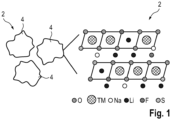
- Fig.1 The structure (ie morphology, crystal structure) of a cathode material 2 according to the invention is shown schematically and in detail.
- the cathode material 2 is an LMR cathode material 2 and contains lithium Li, nickel Ni, manganese Mn and oxygen O and is additionally doped with sodium Na, fluorine F and sulphur S.
- Three particles 4 are shown as examples, and to the right of them the corresponding crystal structure is shown. It can be seen that individual lithium positions are occupied by sodium Na.
- some lithium positions are occupied by nickel Ni and manganese Mn, which in Fig.1 cannot be distinguished and are instead referred to as transition metal TM.
- oxygen positions are not exclusively occupied by oxygen O, but also alternatively by fluorine F and sulfur S.
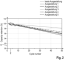
- Fig.2 shows the capacity of a cell with the cathode material 2, where the capacity K is given as a function of the number of cycles Z and relative to the initial capacity (ie capacity retention). It is clearly visible that the cathode material 2 has the highest cycle stability according to the best design.
- Fig.3 shows the resistance DC-IR (DC resistance) for the respective cathode material 2 as a function of the SOC (state of charge). It is clear that the cathode material 2 has the lowest resistance overall according to the best design.
Landscapes
- Chemical & Material Sciences (AREA)
- Chemical Kinetics & Catalysis (AREA)
- Electrochemistry (AREA)
- General Chemical & Material Sciences (AREA)
- Inorganic Chemistry (AREA)
- Engineering & Computer Science (AREA)
- Organic Chemistry (AREA)
- Materials Engineering (AREA)
- Manufacturing & Machinery (AREA)
- Battery Electrode And Active Subsutance (AREA)
Abstract
Es wird ein Kathodenmaterial angegeben, welches zusammengesetzt ist gemäß der Formel LixNayNi1-zMnzO2+a-b-cFb8c, wobei 1,3 ≤ x ≤ 1,6; 0 < y ≤ 0,02; 0,5 ≤ z < 1; 0 < a ≤ 0,5; 0 < b ≤ 0,07; 0 < c ≤ 0,02. Weiter werden ein Verfahren zur Herstellung eines solchen Kathodenmaterials und eine Verwendung des Kathodenmaterials angegeben.
Description
- Die Erfindung betrifft ein Kathodenmaterial, ein Verfahren zu dessen Herstellung und eine Verwendung des Kathodenmaterials.
- Ein Energiespeicher, auch als Batterie bezeichnet, weist allgemein eine Anzahl von Zellen auf, jeweils mit zwei Elektroden, nämlich einer Kathode und einer Anode. Die Elektroden weisen ein je nach Batterietyp geeignet ausgewähltes Kathoden- beziehungsweise Anodenmaterial auf. Eine Ladungsbewegung zwischen den Elektroden wird durch ein zusätzliches Elektrolyt ermöglicht. Ein Beispiel für einen Energiespeicher ist eine Lithium-Ionen-Batterie, mit einer oder mehreren Zellen auf Basis von Lithium. Solche Batterien finden unter anderem Verwendung als Energiespeicher in elektrisch angetriebenen Fahrzeugen, speziell Personenkraftwagen (PKW), Lastkraftwagen (LKW) und Motorrädern.
- Verschiedene Kathodenmaterialien sind beispielsweise beschrieben in
DE 10 2010 006 440 A1 ,DE 10 2015 211 110 A1 undEP 2 736 106 A2 . - Vor diesem Hintergrund ist es eine Aufgabe der Erfindung ein verbessertes Kathodenmaterial anzugeben. Das Kathodenmaterial soll möglichst vorteilhafte elektrochemische Eigenschaften aufweisen und zugleich auch eine möglichst hohe praktische Anwendbarkeit, d.h. für eine tatsächliche Verwendung geeignet sein. Weiterhin soll ein Verfahren zur Herstellung eines solchen Kathodenmaterials angegeben werden.
- Die Aufgabe wird erfindungsgemäß gelöst durch ein Kathodenmaterial mit den Merkmalen gemäß Anspruch 1, ein Verfahren mit den Merkmalen gemäß Anspruch 7 sowie durch eine Verwendung mit den Merkmalen gemäß Anspruch 10. Vorteilhafte Ausgestaltungen, Weiterbildungen und Varianten sind Gegenstand der Unteransprüche. Die Ausführungen im Zusammenhang mit dem Kathodenmaterial gelten sinngemäß auch für das Verfahren sowie die Verwendung und umgekehrt.
- Das erfindungsgemäße Kathodenmaterial enthält die Elemente Lithium (Li), Natrium (Na), Nickel (Ni), Mangan (Mn), Sauerstoff (O), Fluor (F) und Schwefel (S). In einer geeigneten Ausgestaltung enthält das Kathodenmaterial darüber hinaus keine anderen Elemente und besteht dann ausschließlich aus den vorstehend explizit genannten Elementen. Alternativ ist aber zusätzlich zum Nickel noch eine Beimengung eines oder mehrerer anderer Übergangsmetalle (z.B. Cobalt) möglich. Geeigneterweise ist das Kathodenmaterial zusammengesetzt gemäß der Formel LixNayNi1-zMnzO2+a-b-cFbSc, mit den Koeffizienten x, y, z, a, b und c, aus welchen sich gemäß der genannten Formel die Anzahlverhältnisse der einzelnen Elemente untereinander ergeben. Ein solches Kathodenmaterial wird auch als LMR-Kathodenmaterial bezeichnet (LMR = lithium manganese rich). Der Lithiumanteil x ist vorzugsweise größer als 1. Erfindungsgemäß ist das LMR-Kathodenmaterial mit Natrium und Fluor dotiert, wobei im Kristallgitter des Kathodenmaterials das Natrium teilweise Lithium ersetzt, d.h. an Lithiumpositionen angeordnet ist. Gleiches gilt für Nickel und Mangan, welche ebenfalls an Lithiumpositionen angeordnet sind und im Kristallgitter Lithium ersetzen. Analog ersetzt das Fluor teilweise Sauerstoff, d.h. ist an Sauerstoffpositionen angeordnet. Gleiches gilt für Schwefel, welcher ebenfalls an Sauerstoffpositionen angeordnet ist und im Kristallgitter Sauerstoff ersetzen.
- Hinsichtlich der Zusammensetzung des fertigen Kathodenmaterials gilt vorzugsweise: 1,3 ≤ x ≤ 1,6; 0 < y ≤ 0,02; 0,5 ≤ z < 1; 0 < a ≤ 0,5; 0 < b ≤ 0,07; 0 < c ≤ 0,02. Geeignet ist insbesondere eine Ausgestaltung, bei welcher gilt: 1,3 < x < 1,5; 0 < y ≤ 0,01; 0,5 < z < 1; 0 < a < 0,5; 0 < b ≤ 0,04; 0 < c ≤ 0,01. Ganz besonders bevorzugt ist eine Ausgestaltung, bei welcher gilt: x = 1,407; y = 0,0026; z = 0,64; a = 0,413 (d.h. 2+a-b-c = 2.387); b = 0,02; c = 0,006. Diese Ausgestaltung wird auch als "beste Ausgestaltung" oder "Ausgestaltung 0)" bezeichnet und hat sich in Versuchen als besonders leistungsfähig herausgestellt, d.h. weist besonders vorteilhafte elektrochemische Eigenschaften auf und ist auch für praktische Anwendungen besonders geeignet. Alternativ sind auch die folgenden fünf Ausgestaltungen geeignet, für welche gilt:
- Ausgestaltung 1): x = 1,413; y = 0,012; z = 0,65; a = 0,409 (d.h. 2+a-b-c = 2.376); b = 0,02; c = 0,013;
- Ausgestaltung 2): x = 1,415; y = 0,005; z = 0,65; a = 0,422 (d.h. 2+a-b-c = 2.367); b = 0,05; c = 0,005;
- Ausgestaltung 3): x = 1,512; y = 0,006; z = 0,65; a = 0,433 (d.h. 2+a-b-c = 2.386); b = 0,04; c = 0,007;
- Ausgestaltung 4): x = 1,432; y = 0,015; z = 0,65; a = 0,43 (d.h. 2+a-b-c = 2.365); b = 0,06; c = 0,005;
- Ausgestaltung 5): x = 1,421; y = 0,013; z = 0,65; a = 0,399 (d.h. 2+a-b-c = 2.375); b = 0,05; c = 0,019.
- Die elektrochemischen Eigenschaften und damit die Leistungsfähigkeit der vorgenannten Ausgestaltungen 1) bis 5) und der besten Ausgestaltung sind in der nachfolgenden Tabelle 1 zusammengefasst:
Tabelle 1 Ladekapazität [mAh/g] Entladekapazität [mAh/g] Entladekapazität / Ladekapazität [%] Zyklenfestigkeit (cycle retention) über 50 Zyklen und bei 45°C [%] beste Ausgestaltung 318,1 270,2 84,9 98,1 Ausgestaltung 1) 324,1 267,7 82,6 95,2 Ausgestaltung 2) 315,1 265,1 84,1 96,0 Ausgestaltung 3) 332,5 266,4 80,1 95,6 Ausgestaltung 4) 316,7 262,3 82,8 95,9 Ausgestaltung 5) 332,5 267,4 80,4 96,6 - Die Messergebnisse der Tabelle 1 basieren auf einer Elektrodendichte von 3,2 g/cm und einer Grenzspannung von 2,5 V bis 4,7 V.
- Nach der Herstellung liegt das Kathodenmaterial insbesondere in Form eines Konglomerats mit einer Vielzahl an Partikeln vor, welche jeweils eine Partikelgröße aufweisen. Die Partikelgröße ist insbesondere ein mittlerer Durchmesser eines jeweiligen Partikels. Alle Partikelgrößen bilden eine Verteilung, aus welcher eine mittlere Partikelgröße des Kathodenmaterials insgesamt ableitbar ist, z.B. als Mittelwert, Medianwert oder Verteilungsmaximum aller Partikelgrößen. Vorzugsweise weist das Kathodenmaterial eine mittlere Partikelgröße im Bereich von 0,5 µm bis 5 µm auf, besonders bevorzugt im Bereich von 1 µm bis 2 µm. Dadurch weist das Kathodenmaterial eine verbesserte Morphologie auf, speziell für praktische Anwendungen.
- Das Kathodenmaterial weist auch eine Elektrodendichte auf, welche die Dichte des Kathodenmaterials an sich angibt. Vorzugsweise weist das Kathodenmaterial eine Elektrodendichte im Bereich von 3,0 g/cm2 bis 3,5 g/cm2 auf, z.B. 3,2 g/cm2.
- Die Partikel des Kathodenmaterials sind vorzugsweise jeweils ein Einkristall, d.h. die einzelnen Partikel sind monokristallin und gerade nicht polykristallin. Das Kathodenmaterial wird dann auch insgesamt als monokristallin (single crystalline) bezeichnet. Dadurch weist das Kathodenmaterial eine verbesserte Morphologie auf. Im Vergleich zu einem polykristallinen Kathodenmaterial ist das monokristalline Kathodenmaterial weniger bruchempfindlich, d.h. kollabiert weniger einfach, was speziell für das Kalandrieren des Kathodenmaterials im Rahmen der Herstellung einer Kathode für eine Zelle von Vorteil ist. Das Kalandrieren kann nun mit erhöhtem Anpressdruck erfolgen, sodass eine höhere Elektrodendichte erzielt wird. Auch beim Pressen der Kathode während der Herstellung der Zelle, z.B. beim Pressen eines Elektrodenstapels aus mehreren Kathoden und Anoden, ist das monokristalline Kathodenmaterial von Vorteil, um ein Kollabieren und eine daraus resultierende große, aktive Fläche für Nebenreaktionen zu vermeiden.
- Der Erfindung liegt zunächst die Beobachtung zugrunde, dass die Verwendung von Lithiumlonen-Batterien als Energiespeicher in elektrisch angetriebenen Fahrzeugen durch den zur Verfügung stehenden Bauraum beschränkt ist und dies im Konflikt mit einer möglichst hohen Reichweite für das Fahrzeug, d.h. einem möglichst großen Energiespeicher, steht. Daher ist es vorteilhaft, möglichst die Speicherdichte des Energiespeichers zu erhöhen, um bei gleichem Bauraum eine höhere Reichweite zu erzielen. Ein grundsätzlich geeignetes Kathodenmaterial für einen Energiespeicher ist mit Nickel angereichert und weist dann allerdings eine eher geringe theoretische Kapazität von 240 mAh/g auf. Zudem wird der Rohstoff Nickel (und auch vergleichbare Rohstoffe wie Cobalt) zunehmend teurer. Entsprechend ist es wünschenswert, günstigere und zugleich chemisch möglichst vorteilhaftere Alternativen für Kathodenmaterialien zu finden. Solche alternativen Kathodenmaterialien sind Lithium-Mangan-reiche (LMR = lithiummanganese rich) Kathodenmaterialien, deren theoretische Kapazität mit 270 mAh/g oder mehr größer ist als bei den bereits genannten nickelangereicherten Kathodenmaterialien. Der hohe Mangananteil führt auch zu geringeren Kosten. Entsprechend ist das vorliegend vorgestellte Kathodenmaterial grundsätzlich ein LMR-Kathodenmaterial.
- LMR-Kathodenmaterialien weisen jedoch auch diverse Nachteile auf. So beträgt die mittlere Partikelgröße des Kathodenmaterials regelmäßig nur etwa 200 nm oder weniger und das Kathodenmaterial kollabiert sehr schnell, d.h. ist wenig robust. Dadurch ist es schwierig, die Elektrodendichte zu erhöhen, was sich in einer geringen volumetrischen Energiedichte (in Wh/l) niederschlägt. Außerdem ergeben sich speziell durch Kollabieren des Kathodenmaterials unerwünschte Nebenreaktionen mit dem Elektrolyt und daraus resultierende, unerwünschte Effekte, wie z.B. Bruch und Pulverisierung des Kathodenmaterials, elektrische Isolation, Auflösung von Übergangsmetallen im Kathodenmaterial und kontinuierliche Bildung einer sogenannten SEI-Schicht (solid electrolyte interphase layer). Insgesamt ergeben sich daraus verschlechterte elektrochemische Eigenschaften, beispielsweise eine kontinuierliche Abnahme der mittleren Zellspannung, Gasbildung, Erhöhung des internen, elektrischen Widerstands, verminderte Zyklenfestigkeit und eine drastische Abnahme der Kapazität. Letztere ist insbesondere das Resultat einer irreversiblen Sauerstoff-Aktivität bei hoher Grenzspannung (cutoff voltage, z.B. > 4,4 V).
- Zusätzlich zu morphologischen Herausforderungen bei LMR-Kathodenmaterialien ergeben sich weitere Herausforderungen hinsichtlich der Struktur der Kathode. Allgemein weist die Kristallstruktur eines LMR-Kathodenmaterials eine LiMnO2-Komponente (R-3m Struktur) und eine monokline Li2MnO3-Komponente (C2/m Struktur) auf. Die Aktivierung der Li2MnO3-Komponente ist verantwortlich für die hohe Kapazität bei der erstmaligen Ladung einer Zelle mit LMR-Kathodenmaterial. Da dies aber bei hoher Spannung (> 4,4 V) erfolgt, ergeben sich wie bereits angedeutet zugleich eine hohe strukturelle Instabilität sowie Herausforderungen hinsichtlich der Spannungshysterese, einer anfänglich geringen Coulomb-Effizienz (CE), Gasentwicklung, Auflösung des Mangans usw.
- Die genannten Nachteil und Herausforderungen sind vorteilhaft auf verschiedene Weise adressierbar, entsprechend geeignete Maßnahmen sind unabhängig voneinander realisierbar und lassen sich in die folgenden Kategorien einteilen: 1) Oberflächenvorbehandlung, 2) Optimierung der Zusammensetzung, 3) Dotierung und 4) Oberflächenbeschichtung. Im Rahmen einer Oberflächenvorbehandlung ist es vorteilhaft, die Oberfläche der Struktur des Kathodenmaterials hin zu einer Spinell-Struktur zu verändern, um die Diffusion von Lithiumionen zu erhöhen und den internen, elektrischen Widerstand zu verringern. Dadurch ergeben sich eine hohe, anfängliche Entladekapazität und eine hohe Coulomb-Effizienz sowie eine besonders gute Zyklenfestigkeit. Eine geeignete Möglichkeit zur Optimierung der Zusammensetzung des Kathodenmaterials ist eine Veränderung des Anteils an Lithium sowie des Nickel-Mangan-Verhältnisses, mit dem Ziel, eine möglichst geeignete Zusammensetzung des Kathodenmaterials hinsichtlich der Sauerstoffaktivität (speziell Sauerstoffverlust) beim erstmaligen Laden der Zelle zu finden und dadurch die anfängliche Kapazität und Coulomb-Effizienz zu erhöhen. Eine Dotierung und/oder Oberflächenbeschichtung ist vorteilhaft hinsichtlich der praktischen Anwendbarkeit des Kathodenmaterials, d.h. einer Anwendung über den Labormaßstab oder über Testaufbauten hinaus. Dem liegt die Beobachtung zugrunde, dass ein LMR-Kathodenmaterial einen besonders komplexen elektrochemischen Mechanismus aufweist, wodurch die Feinstruktur des Kathodenmaterials eine besondere Bedeutung für dessen praktische Anwendbarkeit und spezifische Kapazität hat. Insbesondere die bereits genannte, sehr geringe Partikelgröße im Nanometerbereich und die Eigenschaft, einfach zu kollabieren (hohe Bruchempfindlichkeit), ergeben eine besonders große, aktive Fläche zur Reaktion mit dem Elektrolyt innerhalb der Zelle. Eine Oberflächenbeschichtung erhöht dann vorteilhaft die Oberflächenstabilität der Kathode und reduziert das Ausmaß unerwünschter Nebenreaktionen mit dem Elektrolyt. Vorteilhaft ist auch ein zusätzlicher Beschichtungs-Precursor, um die Sauerstoffentwicklung zu hemmen und Lücken zu erhalten, welche dennoch durch Sauerstoff-Aktivität (d.h. entweichenden Sauerstoff) entstehen. Dadurch lässt sich der Anteil an irreversiblem Kapazitätsverlust reduzieren. Eine Dotierung erhöht schließlich vorteilhaft die interne Stabilität der Kathode, wodurch eine Abnahme der Kapazität und der mittleren Zellspannung mit zunehmender Zyklenzahl vermindert wird. Die Abnahme der Zellspannung ergibt sich allgemein aus der Migration des Übergangsmetalls im Kathodenmaterial bei hoher Ladung durch eine Transformation von einer Schicht- zu einer Spinell-Struktur. Wenn nun bei der Herstellung, insbesondere Kalzinierung, des Kathodenmaterials dieses im Rahmen einer Dotierung mit einem Fremdstoff dotiert wird, hemmt dieser Fremdstoff vorteilhaft die Transformation von Schicht- zu Spinell-Struktur speziell bei zunehmender Zyklenzahl und reduziert den Widerstand dabei.
- Eine oder mehrere und vorzugsweise alle der genannten Maßnahmen ergeben ein LMR-Kathodenmaterial mit besonders guten elektrochemischen Eigenschaften, allerdings ist die Leistungsfähigkeit hinsichtlich der praktischen Anwendbarkeit, z.B. Verwendung in einem Energiespeicher zum Antrieb eines elektrisch angetriebenen Fahrzeugs, weiterhin möglicherweise eingeschränkt. Die beschriebene Oberflächenvorbehandlung, Optimierung der Zusammensetzung, Dotierung und Oberflächenbeschichtung verbessern zwar die elektrochemische Leistungsfähigkeit, allerdings lediglich für wenig anspruchsvolle Randbedingungen, wie beispielsweise geringe Massenbeladung (mass loading level), geringe Elektrodendichte, geringe C-Rate (d.h. dem Verhältnis von maximalem Lade-/Entladestrom in A zu Kapazität in Ah) und in einer Halbzellenkonfiguration (wie in einem Testaufbau). Für solche Randbedingungen ist das beschriebene, verbesserte LMR-Kathodenmaterial wenigstens gleichwertig zu üblichen nickelreichen Kathodenmaterialien. Eine praktische Anwendbarkeit bedingt jedoch andere Randbedingungen, insbesondere eine hohe Massenbeladung, eine hohe Elektrodendichte, eine hohe C-Rate und die Betrachtung einer vollständigen Zelle (d.h. nicht nur Halbzelle). Die geringe Partikelgröße von etwa 200 nm oder weniger bleibt nachteilig erhalten und die Kathode ist weiterhin bruchempfindlich und deren Struktur kollabiert bereits bei geringem Anpressdruck und somit erst recht beim Kalandrieren. Diese intrinsischen Merkmale führen dazu, dass eine hohe Elektrodendichte schwierig zu erreichen ist, wodurch trotz einer hohen spezifischen Kapazität (> 270 mAh/g) eine lediglich geringe volumetrische Energiedichte erzielt wird. Durch die weiterhin bestehende geringe Partikelgröße und die hohe Bruchempfindlichkeit ist die aktive Fläche besonders groß und ermöglicht somit unerwünschte Nebenreaktionen, Gasentwicklung und kontinuierliche Kapazitäts- sowie Spannungsreduzierung im Verlauf über mehrerer Zyklen, wie bereits beschrieben. Das Problem der geringen Partikelgröße und die damit einhergehenden Nachteile werden vorzugsweise durch eine monokristalline (single crystalline) Konfiguration des Kathodenmaterials behoben, d.h. das Kathodenmaterial ist dann ein monokristallines LMR-Kathodenmaterial. Außerdem sollte das Kathodenmaterial für eine praktische Anwendbarkeit auch entsprechend relevante Tests wie HPPC (hybrid pulse power characterization) bestehen, möglichst wenig Gas entwickeln und bei hoher Temperatur und einem SOC (state of charge) im Bereich von 80 % bis 100 % noch sicher sein.
- Einer oder mehrere der vorgenannten Nachteile werden durch das erfindungsgemäße Kathodenmaterial vorteilhaft behoben. Dieses Kathodenmaterial weist exzellente elektrochemische Eigenschaften auf und ist auch für praktische Anwendungen besonders gut geeignet. Insbesondere zeichnet sich das Kathodenmaterial auch durch eine erhöhte Partikelgröße, Bruchfestigkeit und Elektrodendichte aus.
- Das erfindungsgemäße Kathodenmaterial wird allgemein aus LiNiMnO hergestellt, d.h. bei der Herstellung wird Lithium-Nickel-Mangan-Oxid als Ausgangsmaterial verwendet (das LiNiMnO wird auch als Precursor bezeichnet). Dieses wird mit Natrium, Fluor und Schwefel als weitere Ausgangsmaterialien der Herstellung dotiert (Natrium, Fluor und Schwefel werden auch als Dotierstoffe bezeichnet). Mit anderen Worten: einzelne Atome des LiNiMnO werden durch Fremdatome ersetzt, diese Fremdatome sind Natrium, Fluor und Schwefel. Die Beimengung von Natrium, Fluor und Schwefel führt zu einer erhöhten Energiedichte und einer verbesserten Sicherheit bei hoher Temperatur während der Verwendung. Da ein Natriumatom größer ist als ein Lithiumatom führt das Natrium zudem vorteilhaft zu einer Vergrößerung der Struktur (genauer des ursprünglich vom Lithium eingenommenen Raumbereichs) und unterstützt dadurch die Diffusion von Lithiumionen beim Laden und Entladen. Das Fluor und der Schwefel hingegen binden vorteilhaft besonders stark an den noch verbleibenden Sauerstoff und verringern dadurch dessen Aktivität, d.h. der Sauerstoffverlust insbesondere bei der Verwendung des Kathodenmaterials wird reduziert, zugleich wird die Stabilität der Kathode insgesamt verbessert.
- Das Natrium, das Fluor und der Schwefel werden jeweils entweder elementar oder als Verbindung mit einem oder mehreren anderen Elementen hinzugefügt, welche dann aber vorzugsweise nicht in das Kathodenmaterial eingebaut werden, sondern lediglich als Hilfsstoffe für die Herstellung dienen. In einer bevorzugten Ausgestaltung werden die Ausgangsmaterialien, d.h. LiNiMnO, Natrium, Fluor und Schwefel, trocken gemischt. Dadurch ergibt sich ein trockenes Gemisch, welches dann weiterverarbeitet wird, insbesondere kalziniert wird, um das Kathodenmaterial zu erhalten.
- Vorzugsweise wird das Kathodenmaterial durch eine sauerstofffreie Kalzinierung hergestellt, d.h. die Ausgangsmaterialien werden kalziniert, ohne dass dabei zusätzlich Sauerstoff zugeführt wird. Während der Kalzinierung erfolgt demnach keine Zufuhr von Sauerstoff. Bei der Kalzinierung dringt insbesondere das Natrium in Lithiumpositionen ein und ein Natriumatom ersetzt dort dann das jeweilige Lithiumatom. Analog dringen bei der Kalzinierung insbesondere das Fluor und der Schwefel in Sauerstoffpositionen ein und ein Fluoratom oder Schwefelatom ersetzt dort dann das jeweilige Sauerstoffatom.
- Die beiden vorgenannten Konzepte der trockenen Mischung und der sauerstofffreien Kalzinierung stellen neuartige Konzepte für die Herstellung eines Kathodenmaterials dar und ergeben ein insbesondere wie oben beschrieben verbessertes Kathodenmaterial.
- Das erfindungsgemäße Kathodenmaterial findet vorzugsweise Verwendung in einem Energiespeicher zur Versorgung eines elektrischen Antriebs eines elektrisch angetriebenen Fahrzeugs. Diese Verwendung stellt insbesondere auch eine praktische Anwendung des Kathodenmaterials dar.
- Nachfolgend werden Ausführungsbeispiele der Erfindung anhand einer Zeichnung näher erläutert. Darin zeigen jeweils:
- Fig. 1
- schematisch die Struktur eines Kathodenmaterials,
- Fig. 2
- Kapazität als Funktion von Zyklenzahl für verschiedene Ausgestaltungen des Kathodenmaterials aus
Fig. 1 , - Fig. 3
- Widerstand als Funktion von SOC für verschiedene Ausgestaltungen des Kathodenmaterials aus
Fig. 1 , - Fig. 4
- Bilder für verschiedene Ausgestaltungen des Kathodenmaterials aus
Fig. 1 . - In
Fig. 1 ist schematisch und ausschnittsweise die Struktur (d.h. Morphologie, Kristallstruktur) eines erfindungsgemäßen Kathodenmaterials 2 gezeigt. Das Kathodenmaterial 2 ist ein LMR-Kathodenmaterial 2 und enthält Lithium Li, Nickel Ni, Mangan Mn und Sauerstoff O und ist zusätzlich mit Natrium Na, Fluor F und Schwefel S dotiert. Links inFig. 1 sind exemplarisch drei Partikel 4 gezeigt, rechts davon dann ausschnittsweise die zugehörige Kristallstruktur. Darin ist erkennbar, dass einzelne Lithiumpositionen durch Natrium Na besetzt sind. Außerdem sind einige Lithiumpositionen durch Nickel Ni und Mangan Mn besetzt, welche inFig. 1 nicht unterschieden werden und stattdessen als Übergangsmetall TM bezeichnet sind. Analog sind Sauerstoffpositionen nicht ausschließlich mit Sauerstoff O besetzt, sondern ersatzweise auch mit Fluor F und Schwefel S. - In den
Fig. 2 und3 sind Messergebnisse zu folgenden Ausgestaltungen für das Kathodenmaterial 2 gezeigt: - beste Ausgestaltung: x = 1,407; y = 0,0026; z = 0,64; a = 0,413 (d.h. 2+a-b-c = 2.387); b = 0,02; c = 0,006.
- Ausgestaltung 1): x = 1,413; y = 0,012; z = 0,65; a = 0,409 (d.h. 2+a-b-c = 2.376); b = 0,02; c = 0,013;
- Ausgestaltung 2): x = 1,415; y = 0,005; z = 0,65; a = 0,422 (d.h. 2+a-b-c = 2.367); b = 0,05; c = 0,005;
- Ausgestaltung 3): x = 1,512; y = 0,006; z = 0,65; a = 0,433 (d.h. 2+a-b-c = 2.386); b = 0,04; c = 0,007;
- Ausgestaltung 4): x = 1,432; y = 0,015; z = 0,65; a = 0,43 (d.h. 2+a-b-c = 2.365); b = 0,06; c = 0,005;
- Ausgestaltung 5): x = 1,421; y = 0,013; z = 0,65; a = 0,399 (d.h. 2+a-b-c = 2.375); b = 0,05; c = 0,019.
-
Fig. 2 zeigt die Kapazität einer Zelle mit dem Kathodenmaterial 2, wobei die Kapazität K als Funktion der Zyklenzahl Z und relativ zur anfänglichen Kapazität angegeben ist (d.h. capacity retention). Klar erkennbar ist, dass das Kathodenmaterial 2 gemäß der besten Ausgestaltung die höchste Zyklenfestigkeit aufweist. -
Fig. 3 zeigt den Widerstand DC-IR (DC-Widerstand) für das jeweilige Kathodenmaterial 2 als Funktion des SOC (state of charge). Dabei wird deutlich, dass das Kathodenmaterial 2 gemäß der besten Ausgestaltung insgesamt den geringsten Widerstand aufweist. - In
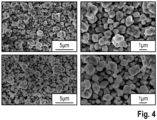
Fig. 4 sind schließlich Bilder von Proben des Kathodenmaterials gemäß der besten Ausgestaltung (oben inFig. 4 ) und der Ausgestaltung 1) (unten inFig. 4 ) gezeigt, jeweils in zwei Vergrößerungsstufen. Deutlich erkennbar sind die verschiedenen Partikel 4. In jedem der vier Bilder ist ein Maßstab eingefügt, um die Partikelgröße zu verdeutlichen. Die Bilder wurden mit einem Rasterelektronenmikroskop (SEM) aufgenommen. -
- 2
- Kathodenmaterial
- 4
- Partikel
- DC-IR
- Widerstand
- F
- Fluor
- K
- Kapazität
- Li
- Lithium
- Na
- Natrium
- TM
- Übergangsmetall (Nickel, Mangan)
- O
- Sauerstoff
- S
- Schwefel
- SOC
- state of charge
- Z
- Zyklenzahl
Claims (10)
- Kathodenmaterial (2),
welches zusammengesetzt ist gemäß der Formel LixNayNi1-zMnzO2+a-b-cFbSc,
wobei1,3 ≤ x ≤ 1,6;0 < y ≤ 0,02;0,5 ≤ z < 1;0 < a ≤ 0,5;0 < b ≤ 0,07;0 < c ≤ 0,02. - Kathodenmaterial (2) nach Anspruch 1,
wobei1,3 < x < 1,5;0 < y ≤ 0,01;0,5 < z < 1;0 < a < 0,5;0 < b ≤ 0,04;0 < c ≤ 0,01. - Kathodenmaterial (2) nach Anspruch 1 oder 2,
wobeix = 1,407;y = 0,0026;z = 0,64;a = 0,413;b = 0,02;c = 0,006. - Kathodenmaterial (2) nach einem der Ansprüche 1 bis 3,
welches eine mittlere Partikelgröße im Bereich von 0,5 µm bis 5 µm aufweist, bevorzugt im Bereich von 1 µm bis 2 µm. - Kathodenmaterial (2) nach einem der Ansprüche 1 bis 4,
welches eine Elektrodendichte im Bereich von 3,0 g/cm2 bis 3,5 g/cm2 aufweist. - Kathodenmaterial (2) nach einem der Ansprüche 1 bis 5,
welches eine Vielzahl von Partikeln (4) enthält, welche jeweils ein Einkristall sind. - Verfahren zur Herstellung eines Kathodenmaterials (2) gemäß einem der Ansprüche 1 bis 6,
wobei das Kathodenmaterial (2) aus LiNiMnO hergestellt wird, welches mit Natrium (Na), Fluor (F) und Schwefel (S) dotiert wird. - Verfahren nach Anspruch 7,
wobei das LiNiMnO, das Natrium (Na), das Fluor (F) und der Schwefel (S) trocken gemischt werden. - Verfahren nach Anspruch 7 oder 8,
wobei das Kathodenmaterial (2) durch eine sauerstofffreie Kalzinierung hergestellt wird. - Verwendung eines Kathodenmaterials (2) nach einem der Ansprüche 1 bis 6 in einem Energiespeicher zur Versorgung eines elektrischen Antriebs eines elektrisch angetriebenen Fahrzeugs.
Applications Claiming Priority (1)
| Application Number | Priority Date | Filing Date | Title |
|---|---|---|---|
| DE102022213054.5A DE102022213054B3 (de) | 2022-12-05 | 2022-12-05 | Kathodenmaterial, Verfahren zu dessen Herstellung und Verwendung des Kathodenmaterials |
Publications (1)
| Publication Number | Publication Date |
|---|---|
| EP4382490A1 true EP4382490A1 (de) | 2024-06-12 |
Family
ID=88793121
Family Applications (1)
| Application Number | Title | Priority Date | Filing Date |
|---|---|---|---|
| EP23209291.6A Pending EP4382490A1 (de) | 2022-12-05 | 2023-11-13 | Kathodenmaterial, verfahren zu dessen herstellung und verwendung des kathodenmaterials |
Country Status (4)
| Country | Link |
|---|---|
| EP (1) | EP4382490A1 (de) |
| KR (1) | KR20240083845A (de) |
| CN (1) | CN118156503A (de) |
| DE (1) | DE102022213054B3 (de) |
Citations (3)
| Publication number | Priority date | Publication date | Assignee | Title |
|---|---|---|---|---|
| DE102010006440A1 (de) | 2010-02-01 | 2011-08-04 | o.m.t. GmbH, 23569 | Elektrodenmaterial für wiederaufladbare (Sekundär-)batterien auf Lithiumbasis |
| EP2736106A2 (de) | 2012-11-22 | 2014-05-28 | Samsung Fine Chemicals Co., Ltd. | Aktives Kathodenmaterial, Verfahren zu dessen Herstellung, und Lithiumsekundärbatterien damit |
| DE102015211110A1 (de) | 2015-06-17 | 2016-12-22 | Robert Bosch Gmbh | Aktivmaterial für eine Kathode einer Batteriezelle, Kathode und Batteriezelle |
Family Cites Families (2)
| Publication number | Priority date | Publication date | Assignee | Title |
|---|---|---|---|---|
| EP3966884A4 (de) | 2019-05-09 | 2023-07-12 | A123 Systems, LLC | Verfahren und systeme zur trockenflächendotierung von kathodenmaterialien |
| CN112072114A (zh) | 2020-09-17 | 2020-12-11 | 中南大学 | 一种阴阳离子共掺杂的富锂锰基正极材料及其制备方法和应用 |
-
2022
- 2022-12-05 DE DE102022213054.5A patent/DE102022213054B3/de active Active
-
2023
- 2023-11-13 EP EP23209291.6A patent/EP4382490A1/de active Pending
- 2023-12-04 KR KR1020230173684A patent/KR20240083845A/ko active Pending
- 2023-12-05 CN CN202311651866.4A patent/CN118156503A/zh active Pending
Patent Citations (3)
| Publication number | Priority date | Publication date | Assignee | Title |
|---|---|---|---|---|
| DE102010006440A1 (de) | 2010-02-01 | 2011-08-04 | o.m.t. GmbH, 23569 | Elektrodenmaterial für wiederaufladbare (Sekundär-)batterien auf Lithiumbasis |
| EP2736106A2 (de) | 2012-11-22 | 2014-05-28 | Samsung Fine Chemicals Co., Ltd. | Aktives Kathodenmaterial, Verfahren zu dessen Herstellung, und Lithiumsekundärbatterien damit |
| DE102015211110A1 (de) | 2015-06-17 | 2016-12-22 | Robert Bosch Gmbh | Aktivmaterial für eine Kathode einer Batteriezelle, Kathode und Batteriezelle |
Non-Patent Citations (4)
| Title |
|---|
| LIU DONGMING ET AL: "A cation/anion co-doped Li1.12Na0.08Ni0.2Mn0.6O1.95F0.05 cathode for lithium ion batteries", NANO ENERGY, vol. 58, 1 April 2019 (2019-04-01), NL, pages 786 - 796, XP093148425, ISSN: 2211-2855, DOI: 10.1016/j.nanoen.2019.01.080 * |
| SUN ZHENHE ET AL: "A facile gaseous sulfur treatment strategy for Li-rich and Ni-rich cathode materials with high cycling and rate performance", NANO ENERGY, vol. 63, 1 September 2019 (2019-09-01), NL, pages 103887, XP093148428, ISSN: 2211-2855, DOI: 10.1016/j.nanoen.2019.103887 * |
| VANAPHUTI PANAWAN ET AL: "Systematic Study of Different Anion Doping on the Electrochemical Performance of Cobalt-Free Lithium-Manganese-Rich Layered Cathode", ACS APPLIED ENERGY MATERIALS, vol. 3, no. 5, 22 April 2020 (2020-04-22), pages 4852 - 4859, XP093148472, ISSN: 2574-0962, DOI: 10.1021/acsaem.0c00439 * |
| WANG HUA ET AL: "Effect of Cationic (Na+) and Anionic (F-) Co-Doping on the Structural and Electrochemical Properties of LiNi1/3Mn1/3Co1/3O2 Cathode Material for Lithium-Ion Batteries", INTERNATIONAL JOURNAL OF MOLECULAR SCIENCES, vol. 23, no. 12, 17 June 2022 (2022-06-17), Basel, CH, pages 6755, XP093148427, ISSN: 1422-0067, DOI: 10.3390/ijms23126755 * |
Also Published As
| Publication number | Publication date |
|---|---|
| DE102022213054B3 (de) | 2024-03-28 |
| KR20240083845A (ko) | 2024-06-12 |
| CN118156503A (zh) | 2024-06-07 |
Similar Documents
| Publication | Publication Date | Title |
|---|---|---|
| DE112012006684B4 (de) | Kompositkathodenmatrialien mit gesteuertem irreversiblem Kapazitätsverlust für Lithiumionenbatterien | |
| EP1665447B1 (de) | Elektrochemische batteriezelle | |
| DE102008050692B4 (de) | Kohlenstoffbeschichteter Lithiumtitan-Spinell | |
| DE212023000439U1 (de) | Batterieeinheit, Batterie und stromverbrauchendes Gerät | |
| DE112014006437T5 (de) | Kathodenaktivmaterial, Lithiumsekundärbatterie mit demselben und Verfahren zur Zubereitung desselben | |
| DE112012004372T5 (de) | Sekundärbatterie mit nicht wässrigem elektrolyten und verfahren zur herstellung der selben | |
| DE112011103262T5 (de) | Batteriesinterkörper, Herstellungsverfahren des Batteriesinterkörpers und Festkörperlithiumbatterie | |
| DE102012208608A1 (de) | Verfahren zum Herstellen einer Elektrode für einen elektrochemischen Energiespeicher und Elektrode | |
| DE102017223645B4 (de) | Verfahren zur Herstellung eines Verbundmaterials, Verfahren zur Herstellung einer Kathode für eine Festkörperzelle, die dieses Verbundmaterial umfasst, Kathodenmaterial und Festkörperbatterie, die dieses Verbundmaterial umfassen, und elektrisch angetriebenes Fahrzeug, das diese Festkörperbatterie umfasst | |
| DE112013005400T5 (de) | Sekundärbatterie und Verfahren zu ihrer Herstellung | |
| DE102014223147A1 (de) | Chromdotiertes Lithium-Titanat als Kathodenmaterial | |
| EP2573845A1 (de) | Strukturstabiles Aktivmaterial für Batterieelektroden | |
| EP3308418A1 (de) | Na-dotiertes und nb-, w- und/oder mo-dotiertes he-ncm | |
| DE102020123448A1 (de) | Kathodenaktives Material für Lithium-Sekundärbatterie und Verfahren zur Herstellung desselben | |
| DE112023004512T5 (de) | Material aus einer ternären co-dopierung mit lithium-mangan-eisen-phosphat, verfahren zu seiner herstellung und seine verwendung | |
| WO2012076229A1 (de) | Natrium-chalkogen-zelle | |
| EP3120400B1 (de) | Elektrode für eine lithium-zelle | |
| DE102019132932A1 (de) | Elektrolytlösung für lithium-eisen-phosphat-basierte lithium-sekundärbatterie und diese enthaltende lithium-sekundärbatterie | |
| DE102021128484A1 (de) | Festkörperbatterie | |
| DE102012200080A1 (de) | Eisendotiertes Lithiumtitanat als Kathodenmaterial | |
| DE102022213054B3 (de) | Kathodenmaterial, Verfahren zu dessen Herstellung und Verwendung des Kathodenmaterials | |
| EP4092779A1 (de) | Sekundärpartikel für eine kathode einer sekundären lithium-batteriezelle sowie verfahren zur herstellung eines solchen | |
| DE102018219586A1 (de) | Beschichtung von Anoden- und Kathodenaktivmaterialien mit hochvoltstabilen Festelektrolyten und einem Elektronenleiter im Mehrschichtsystem und Lithium-Ionen-Batteriezelle | |
| DE102020121545A1 (de) | Lithium-Ionen-Zelle mit hoher Energiedichte und aktives Anodenmaterial dafür | |
| DE102019201479A1 (de) | Zyklieren von überlithiierten, schichtartigen Übergangsmetall-Oxiden mit hohen oberen Abschaltspannungen |
Legal Events
| Date | Code | Title | Description |
|---|---|---|---|
| PUAI | Public reference made under article 153(3) epc to a published international application that has entered the european phase |
Free format text: ORIGINAL CODE: 0009012 |
|
| STAA | Information on the status of an ep patent application or granted ep patent |
Free format text: STATUS: THE APPLICATION HAS BEEN PUBLISHED |
|
| AK | Designated contracting states |
Kind code of ref document: A1 Designated state(s): AL AT BE BG CH CY CZ DE DK EE ES FI FR GB GR HR HU IE IS IT LI LT LU LV MC ME MK MT NL NO PL PT RO RS SE SI SK SM TR |
|
| STAA | Information on the status of an ep patent application or granted ep patent |
Free format text: STATUS: REQUEST FOR EXAMINATION WAS MADE |
|
| 17P | Request for examination filed |
Effective date: 20241212 |
|
| RAP1 | Party data changed (applicant data changed or rights of an application transferred) |
Owner name: POWERCO SE |