EP4381963A1 - Equipment and method for winding filling rod - Google Patents
Equipment and method for winding filling rod Download PDFInfo
- Publication number
- EP4381963A1 EP4381963A1 EP21952763.7A EP21952763A EP4381963A1 EP 4381963 A1 EP4381963 A1 EP 4381963A1 EP 21952763 A EP21952763 A EP 21952763A EP 4381963 A1 EP4381963 A1 EP 4381963A1
- Authority
- EP
- European Patent Office
- Prior art keywords
- wrapping
- filler
- garniture tape
- wrapping paper
- suction
- Prior art date
- Legal status (The legal status is an assumption and is not a legal conclusion. Google has not performed a legal analysis and makes no representation as to the accuracy of the status listed.)
- Granted
Links
Images


Classifications
-
- A—HUMAN NECESSITIES
- A24—TOBACCO; CIGARS; CIGARETTES; SIMULATED SMOKING DEVICES; SMOKERS' REQUISITES
- A24C—MACHINES FOR MAKING CIGARS OR CIGARETTES
- A24C5/00—Making cigarettes; Making tipping materials for, or attaching filters or mouthpieces to, cigars or cigarettes
- A24C5/14—Machines of the continuous-rod type
- A24C5/18—Forming the rod
- A24C5/1807—Forming the rod with compressing means, e.g. garniture
-
- A—HUMAN NECESSITIES
- A24—TOBACCO; CIGARS; CIGARETTES; SIMULATED SMOKING DEVICES; SMOKERS' REQUISITES
- A24C—MACHINES FOR MAKING CIGARS OR CIGARETTES
- A24C5/00—Making cigarettes; Making tipping materials for, or attaching filters or mouthpieces to, cigars or cigarettes
- A24C5/14—Machines of the continuous-rod type
- A24C5/18—Forming the rod
- A24C5/1885—Forming the rod for cigarettes with an axial air duct
-
- A—HUMAN NECESSITIES
- A24—TOBACCO; CIGARS; CIGARETTES; SIMULATED SMOKING DEVICES; SMOKERS' REQUISITES
- A24C—MACHINES FOR MAKING CIGARS OR CIGARETTES
- A24C5/00—Making cigarettes; Making tipping materials for, or attaching filters or mouthpieces to, cigars or cigarettes
- A24C5/14—Machines of the continuous-rod type
- A24C5/20—Reels; Supports for bobbins; Other accessories
Definitions
- the wrapping paper When the frictional force is applied between the wrapping paper and the garniture tape, the wrapping paper is allowed to run along the forming groove together with the garniture tape, and the wrapping paper is allowed to continuously wrap the filler.
- a tobacco rod filled with a tobacco raw material is defined as a filler rod filled with a flavor raw material (there can be a case where a tobacco raw material is not contained) in a broad sense.
- a filled part obtained by cutting the filler rod is a component of a heat-not-burn flavor inhaling article.
- a heater of a device used to use the flavor inhaling article heats the filled part when inserted into the filled part and generates an aerosol of a flavor component.
- the resistance to insert the heater to the filled part increases to make it difficult to insert the heater, with the result that operability during inhalation deteriorates.
- the resistance to insert the heater may lead to breakage of the heater.
- the filling amount of flavor raw material when the filling amount of flavor raw material is large for the size of the heater, the flavor raw material in the filled part becomes excessively dense as a result of insertion of the heater, so air permeability in the filled part deteriorates, with the result that an inhalation taste may be impaired.
- the filling amount of flavor raw material that fills the filler rod can be reduced as compared to the existing art. In consideration of a situation in terms of costs for a flavor inhaling article, the filling amount of flavor raw material can be reduced.
- the present invention is made in view of such a problem, and it is an object of the present invention to provide a wrapping machine and a wrapping method for a filler rod, capable of manufacturing a desired filler rod even when the filling amount of flavor raw material is reduced.
- the wrapping method includes: a conveying step of, by using a garniture tape that runs along the conveying path and a forming bed having a forming groove along which the garniture tape runs, supplying the wrapping paper onto the garniture tape and supplying the filler onto the wrapping paper and conveying the wrapping paper and the filler together with the garniture tape by causing the wrapping paper and the filler together with the garniture tape to run along the forming groove; and a wrapping step of continuously wrapping the filler with the wrapping paper via the garniture tape to be formed into the filler rod.
- a suction process of applying suction force to the wrapping paper via a suction hole perforated in the garniture tape by sucking a groove space of the forming groove.
- Fig. 1 is a schematic diagram of a filler rod manufacturing machine 1.
- the filler rod manufacturing machine 1 includes a suction band 2.
- the suction band 2 has an endless shape.
- a flavor layer TL is formed on the lower surface of the suction band 2 by adsorbing a flavor raw material in a layer.
- the flavor layer TL is transferred in a conveying direction of the conveying path 4, indicated by the arrow A.
- a flavor raw material that is a component of a filler B of a filler rod is, for example, shredded tobacco, an article obtained by shredding a tobacco sheet, or an article obtained by gathering a tobacco sheet.
- a flavor raw material may be an article obtained by adding a flavoring agent to a sheet made from pulp not containing tobacco, an article obtained by shredding a sheet made from a non-tobacco plant, or an article obtained by gathering a sheet of any one of them.
- a wrapping machine 6 is disposed downstream of the suction band 2 in a conveying direction A of the conveying path 4.
- the wrapping machine 6 forms the flavor layer TL into a filler B and continuously wraps the filler B with the wrapping paper P to be formed into a filler rod TR.
- the wrapping machine 6 includes a garniture tape 8, a forming bed 10, and a drive drum 12.
- the garniture tape 8 has an endless shape and is wound around the drive drum 12. With the rotation of the drive drum 12, part of the garniture tape 8 runs along the conveying path 4.
- the forming bed 10 has a forming groove 14 along which the garniture tape 8 runs.
- a wrapping paper P is supplied onto the garniture tape 8 and runs along the forming groove 14 with the garniture tape 8.
- the shoe 16 peels the flavor layer TL from the suction band 2 and guides the flavor layer TL to the wrapping paper P.
- the tong 18 cooperate with the forming groove 14 of the forming bed 10 to compression-form the flavor layer TL into the filler B.
- the filler B having passed by the tong 18 passes by the short holder 20, the long holder 22, and the heater 24 with the garniture tape 8 and the wrapping paper P.
- a suction hole 36 is perforated in the garniture tape 8. Suction force from the suction chamber 32 is applied to the wrapping paper P via the suction hole 36 of the garniture tape 8. Furthermore, a cooling passage 38 is formed in the forming bed 10. The cooling passage 38 receives coolant circulated and supplied from outside to cool particularly the forming groove 14 of the forming bed 10.
- Fig. 3 is a partially top view of the garniture tape 8.
- a plurality of the suction holes 36 is provided along an extension direction of the garniture tape 8.
- the hole shape of the suction hole 36 may be circular or may be rectangular.
- Various patterns are presumed as the size and formation range of one suction hole 36.
- the number of lines of the suction holes 36 may be one as shown in Fig. 3 or may be multiple.
- suction force from the suction chambers 32 is applied to the wrapping paper P via the suction holes 36 perforated in the garniture tape 8 (suction process).
- suction force is applied to the wrapping paper P via the plurality of suction holes 36 provided in the extension direction of the garniture tape 8.
- step S2 the forming groove 14 of the forming bed is cooled with coolant circulating in the cooling passage 38 (cooling process).
- the wrapping method has been described by being separated into step S1, step S2, process P1, and process P2 for the sake of description; however, step S1, step S2, process P1, and process P2 are performed at the same timing from when wrapping of the filler rod TR is started to when the wrapping ends.
- the forming bed 10 has the suction chambers 32, and the garniture tape 8 has the suction holes 36.
- suction force from the suction chambers 32 is applied to the wrapping paper P via the suction holes 36.
- the garniture tape 8 When the hardness of the filler B is lower than 70%, the garniture tape 8, the wrapping paper P, and the filler B are difficult to run together due to a decrease in frictional force between the wrapping paper P and the garniture tape 8, so the flavor raw material is, for example, left to clog the forming groove 14, and there is a possibility that a desired filler rod TR cannot be manufactured.
- a decrease in frictional force between the wrapping paper P and the garniture tape 8 can be compensated by suction force from the suction chambers 32.
- the plurality of suction chambers 32 is perforated in the forming groove 14 along the conveying path 4.
- suction force from the suction chambers 32 can be further effectively applied to the garniture tape 8 and the wrapping paper P over all the range of the forming groove 14 in the conveying direction A. Therefore, the above-described decrease in frictional force can be further effectively compensated by suction force from the suction chambers 32.
- the forming bed 10 has the cooling passage 38, and the forming groove 14 is cooled in the cooling process of the wrapping step.
- the garniture tape 8 in running excessively contacts with the forming groove 14 due to suction force from the suction chambers 32, heat of friction is generated in the garniture tape 8 and the forming groove 14.
- coolant is circulated in the cooling passage 38 to cool the forming groove 14
- high temperature of the garniture tape 8 and the forming groove 14 due to heat of friction is suppressed. Therefore, it is possible to suppress denaturation of the filler rod TR due to high temperature, so it is possible to ensure the quality of the filler rod TR.
- the forming bed 10 includes the cooling passage 38 inside; however, the cooling passage 38 is not always indispensable.
- the cooling passage 38 is not always indispensable.
- frictional force of the garniture tape 8 against the forming groove 14 is reduced by controlling the suction pressure of the suction source, it is possible to smoothly cause the garniture tape 8 to run in the forming groove 14 while suppressing generation of heat of friction in the forming groove 14, so it is possible to manufacture a desired filler rod TR even when the forming groove 14 is not cooled.
- the suction process may use means other than forming the suction chambers 32 in the forming bed 10 as long as suction force can be applied to the wrapping paper P via the suction holes 36 of the garniture tape 8.
- the cooling process may use means other than forming the cooling passage 38 in the forming bed 10 as long as it is possible to cool the forming groove 14.
- the above-described embodiment is not limited to the wrapping machine 6 and the wrapping method for a filler rod TR used in a heat-not-burn flavor inhaling article and may also be applied to the wrapping machine 6 and the wrapping method for a filler rod TR used in a heat-burn flavor inhaling article.
Landscapes
- Manufacturing Of Cigar And Cigarette Tobacco (AREA)
- Basic Packing Technique (AREA)
- Sanitary Thin Papers (AREA)
Abstract
Description
- The present invention relates to a wrapping machine and a wrapping method for a filler rod.
- PTL 1 describes a wrapping machine for a tobacco rod. The wrapping machine conveys a tobacco raw material, such as shredded tobacco, with a wrapping paper along a conveying path. In the conveying process, the wrapping machine forms a tobacco raw material into a filler while continuously wrapping the filler with the wrapping paper. The wrapping machine includes a garniture tape that runs along the conveying path, and a forming bed having a forming groove along which the garniture tape runs.
- A wrapping paper is supplied onto the garniture tape and runs along the forming groove with the garniture tape. A filler made of a tobacco raw material is supplied onto the wrapping paper and is continuously wrapped with the wrapping paper via the garniture tape running along the forming groove to be formed into a tobacco rod. When the filler runs along the forming groove with the garniture tape and the wrapping paper, the wrapping paper and the garniture tape contact with each other upon receiving the weight of the filler, with the result that frictional force is applied between the wrapping paper and the garniture tape.
- When the frictional force is applied between the wrapping paper and the garniture tape, the wrapping paper is allowed to run along the forming groove together with the garniture tape, and the wrapping paper is allowed to continuously wrap the filler.
- PTL 1:
Japanese Unexamined Patent Application Publication No. 2009-183248 - A tobacco rod filled with a tobacco raw material is defined as a filler rod filled with a flavor raw material (there can be a case where a tobacco raw material is not contained) in a broad sense. In this case, a filled part obtained by cutting the filler rod is a component of a heat-not-burn flavor inhaling article. A heater of a device used to use the flavor inhaling article, for example, heats the filled part when inserted into the filled part and generates an aerosol of a flavor component. In this case, in the filled part, when the filling amount of flavor raw material is large for the size of the heater, the resistance to insert the heater to the filled part increases to make it difficult to insert the heater, with the result that operability during inhalation deteriorates. The resistance to insert the heater may lead to breakage of the heater.
- Furthermore, in the filled part, when the filling amount of flavor raw material is large for the size of the heater, the flavor raw material in the filled part becomes excessively dense as a result of insertion of the heater, so air permeability in the filled part deteriorates, with the result that an inhalation taste may be impaired. To eliminate these inconveniences, the filling amount of flavor raw material that fills the filler rod can be reduced as compared to the existing art. In consideration of a situation in terms of costs for a flavor inhaling article, the filling amount of flavor raw material can be reduced.
- When the filling amount of flavor raw material is reduced, a packing density of filler made of a flavor raw material decreases, so the hardness of the filler decreases, that is, the filler softens. As a result of softening of the filler, the reaction force of the filler decreases, in other words, the filler is difficult to elastically deform, so adhesion between the wrapping paper and the garniture tape at the time when the wrapping paper and the garniture tape run along the forming groove and the frictional force between the wrapping paper and the garniture tape decreases. As a result, in the forming groove, the garniture tape, the wrapping paper, and the filler are difficult to run together, so the flavor raw material is, for example, left to clog the forming groove, and there is a possibility that a desired filler rod cannot be manufactured.
- The present invention is made in view of such a problem, and it is an object of the present invention to provide a wrapping machine and a wrapping method for a filler rod, capable of manufacturing a desired filler rod even when the filling amount of flavor raw material is reduced.
- A wrapping machine for a filler rod according to an aspect is a wrapping machine for a filler rod. The wrapping machine, in a process of conveying a flavor raw material along a conveying path with a wrapping paper, forms the flavor raw material into a filler and continuously wraps the filler with the wrapping paper. The wrapping machine includes a garniture tape that runs along the conveying path, and a forming bed having a forming groove along which the garniture tape runs. The wrapping paper is supplied onto the garniture tape and runs along the forming groove with the garniture tape. The filler is supplied onto the wrapping paper and is continuously wrapped with the wrapping paper via the garniture tape running along the forming groove to be formed into the filler rod. The forming bed has a suction chamber that sucks a groove space in the forming groove. A suction hole is perforated in the garniture tape, and suction force from the suction chamber is applied to the wrapping paper via the suction hole.
- A wrapping method for a filler rod according to an aspect is a wrapping method for a filler rod. The wrapping method, in a process of conveying a flavor raw material along a conveying path with a wrapping paper, forms the flavor raw material into a filler and continuously wraps the filler with the wrapping paper. The wrapping method includes: a conveying step of, by using a garniture tape that runs along the conveying path and a forming bed having a forming groove along which the garniture tape runs, supplying the wrapping paper onto the garniture tape and supplying the filler onto the wrapping paper and conveying the wrapping paper and the filler together with the garniture tape by causing the wrapping paper and the filler together with the garniture tape to run along the forming groove; and a wrapping step of continuously wrapping the filler with the wrapping paper via the garniture tape to be formed into the filler rod. In the wrapping step, a suction process of applying suction force to the wrapping paper via a suction hole perforated in the garniture tape by sucking a groove space of the forming groove.
- With the wrapping machine and the wrapping method for a filler rod, even when the filling amount of flavor raw material is reduced, it is possible to manufacture a desired filler rod.
-
- [
Fig. 1] Fig. 1 is a schematic diagram of a filler rod manufacturing machine. - [
Fig. 2] Fig. 2 is a partially sectional view of a wrapping machine, taken along the line C-C inFig. 1 . - [
Fig. 3] Fig. 3 is a partially top view of a garniture tape. - [
Fig. 4] Fig. 4 is a flowchart that illustrates a wrapping method for a filler rod. -
Fig. 1 is a schematic diagram of a filler rod manufacturing machine 1. The filler rod manufacturing machine 1 includes asuction band 2. Thesuction band 2 has an endless shape. A flavor layer TL is formed on the lower surface of thesuction band 2 by adsorbing a flavor raw material in a layer. The flavor layer TL is transferred in a conveying direction of the conveying path 4, indicated by the arrow A. - A flavor raw material that is a component of a filler B of a filler rod is, for example, shredded tobacco, an article obtained by shredding a tobacco sheet, or an article obtained by gathering a tobacco sheet. Alternatively, a flavor raw material may be an article obtained by adding a flavoring agent to a sheet made from pulp not containing tobacco, an article obtained by shredding a sheet made from a non-tobacco plant, or an article obtained by gathering a sheet of any one of them.
- A
wrapping machine 6 according to the present embodiment is disposed downstream of thesuction band 2 in a conveying direction A of the conveying path 4. In a process of transferring the flavor layer TL made of a flavor raw material with a wrapping paper P made of a paper web along the conveying path 4, thewrapping machine 6 forms the flavor layer TL into a filler B and continuously wraps the filler B with the wrapping paper P to be formed into a filler rod TR. - The
wrapping machine 6 includes agarniture tape 8, a formingbed 10, and adrive drum 12. Thegarniture tape 8 has an endless shape and is wound around thedrive drum 12. With the rotation of thedrive drum 12, part of thegarniture tape 8 runs along the conveying path 4. The formingbed 10 has a forminggroove 14 along which the garniture tape 8 runs. A wrapping paper P is supplied onto thegarniture tape 8 and runs along the forminggroove 14 with thegarniture tape 8. - A filler B is supplied onto the wrapping paper P and is continuously wrapped with the wrapping paper P via the
garniture tape 8 running along the forminggroove 14 to be formed into a filler rod TR. Ashoe 16,tong 18, ashort holder 20, along holder 22, and aheater 24 are disposed in thewrapping machine 6 in order from an upstream side of the conveying path 4 in the conveying direction A. Theshoe 16 and thetong 18 cooperate with the formingbed 10 to make up acompression forming unit 26 for compression-forming the flavor layer TL into the filler B. - The
shoe 16 peels the flavor layer TL from thesuction band 2 and guides the flavor layer TL to the wrapping paper P. When thegarniture tape 8 runs and the flavor layer TL supplied onto the wrapping paper P passes by thetong 18 with thegarniture tape 8, thetong 18 cooperate with the forminggroove 14 of the formingbed 10 to compression-form the flavor layer TL into the filler B. The filler B having passed by thetong 18 passes by theshort holder 20, thelong holder 22, and theheater 24 with thegarniture tape 8 and the wrapping paper P. - At this time, the filler B is continuously wrapped with the wrapping paper P and is formed into the filler rod TR. Both side edges of the wrapping paper P are placed on top of each other via an adhesive to form a seam of the wrapping paper P on the filler rod TR. The adhesive at the seam is dried when the filler rod TR passes by the
heater 24. The filler rod TR sent out from the wrappingmachine 6 passes through a cuttingunit 28 and is cut with a predetermined length. The cut filler rod TR is conveyed to a filter attachment unit (not shown) in a downstream process to be a filled part of a heat-not-burn flavor inhaling article. -
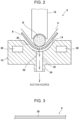
Fig. 2 is a partially sectional view of the wrappingmachine 6, taken along the line C-C inFig. 1 . Asuction chamber 32 for sucking agroove space 30 of the forminggroove 14 is formed in the formingbed 10 of the wrappingmachine 6 according to the present embodiment. A plurality of thesuction chambers 32 is perforated in the forminggroove 14 along the conveying path 4. As shown inFig. 1 , thesuction chambers 32 respectively communicate with a plurality ofsuction ports 34 formed in the formingbed 10, and thesuction ports 34 communicate with a suction source. - A
suction hole 36 is perforated in thegarniture tape 8. Suction force from thesuction chamber 32 is applied to the wrapping paper P via thesuction hole 36 of thegarniture tape 8. Furthermore, acooling passage 38 is formed in the formingbed 10. Thecooling passage 38 receives coolant circulated and supplied from outside to cool particularly the forminggroove 14 of the formingbed 10. -
Fig. 3 is a partially top view of thegarniture tape 8. A plurality of the suction holes 36 is provided along an extension direction of thegarniture tape 8. The hole shape of thesuction hole 36 may be circular or may be rectangular. Various patterns are presumed as the size and formation range of onesuction hole 36. The number of lines of the suction holes 36 may be one as shown inFig. 3 or may be multiple. -
Fig. 4 is a flowchart that illustrates a wrapping method for a filler rod TR. When wrapping of the filler rod TR is started, in step S1, as described above, the wrapping paper P is supplied onto thegarniture tape 8, the filler B is supplied onto the wrapping paper P, and the wrapping paper P and the filler B are conveyed so as to run with thegarniture tape 8 along the forming groove 14 (conveying step). In step S2, as described above, the filler B is continuously wrapped with the wrapping paper P via thegarniture tape 8 to be formed into the filler rod TR (wrapping step). - In the wrapping step, in process P1, by sucking the
groove space 30 of the forminggroove 14, suction force from thesuction chambers 32 is applied to the wrapping paper P via the suction holes 36 perforated in the garniture tape 8 (suction process). In the suction process, suction force is applied to the wrapping paper P via the plurality of suction holes 36 provided in the extension direction of thegarniture tape 8. - In the wrapping step, in process P2, the forming
groove 14 of the forming bed is cooled with coolant circulating in the cooling passage 38 (cooling process). The wrapping method has been described by being separated into step S1, step S2, process P1, and process P2 for the sake of description; however, step S1, step S2, process P1, and process P2 are performed at the same timing from when wrapping of the filler rod TR is started to when the wrapping ends. - As described above, in the
wrapping machine 6 and the wrapping method for the filler rod TR according to the present embodiment, the formingbed 10 has thesuction chambers 32, and thegarniture tape 8 has the suction holes 36. In the suction process of the wrapping step, suction force from thesuction chambers 32 is applied to the wrapping paper P via the suction holes 36. - As described above, when the filling amount of flavor raw material is reduced as compared to the existing art, frictional force applied between the wrapping paper P and the
garniture tape 8 reduces due to softening of the filler B. More specifically, when the hardness of the filler B is lower than 70%, it is difficult to manufacture the filler rod TR, so it has been proved that the hardness of the filler B needs to be higher than or equal to 70% and more preferably higher than or equal to 75%. - The hardness of the filler B is measured with a measuring instrument (model number: DD60A Densimeter (made by Heinr. Borgwaldt GmbH)). The measuring instrument includes a pusher and applies a rod on the filler rod TR by lowering the pusher by a lowering distance d. Where the diameter of the filler rod TR before application of a load is Ds and the diameter of the filler rod TR after a load is applied for a predetermined period of time is Dd, the lowering distance d of the pusher is calculated by the expression Ds - Dd, and the hardness of the filler B is calculated by the expression (Dd/Ds) × 100.
- When the hardness of the filler B is lower than 70%, the
garniture tape 8, the wrapping paper P, and the filler B are difficult to run together due to a decrease in frictional force between the wrapping paper P and thegarniture tape 8, so the flavor raw material is, for example, left to clog the forminggroove 14, and there is a possibility that a desired filler rod TR cannot be manufactured. On the other hand, in the present embodiment, even when the hardness of the filler B is lower than 70%, a decrease in frictional force between the wrapping paper P and thegarniture tape 8 can be compensated by suction force from thesuction chambers 32. - Thus, even when the filling amount of flavor raw material is reduced as compared to the existing art, it is possible to enhance adhesion between the
garniture tape 8 and the wrapping paper P in running, so it is possible to cause thegarniture tape 8, the wrapping paper P, and the filler B to run together. Therefore, an inconvenience that the filler B is left to clog the forminggroove 14 can be suppressed. In other words, irrespective of the filling amount and packing density of flavor raw material or irrespective of the hardness of the filler B, a desired filler rod TR can be manufactured. - The plurality of suction holes 36 is provided along the extension direction of the
garniture tape 8. Thus, suction force from thesuction chambers 32 can be further effectively applied to the wrapping paper P. Thus, the above-described decrease in frictional force can be further effectively compensated by suction force from thesuction chambers 32. - The plurality of
suction chambers 32 is perforated in the forminggroove 14 along the conveying path 4. Thus, suction force from thesuction chambers 32 can be further effectively applied to thegarniture tape 8 and the wrapping paper P over all the range of the forminggroove 14 in the conveying direction A. Therefore, the above-described decrease in frictional force can be further effectively compensated by suction force from thesuction chambers 32. - The forming
bed 10 has thecooling passage 38, and the forminggroove 14 is cooled in the cooling process of the wrapping step. When thegarniture tape 8 in running excessively contacts with the forminggroove 14 due to suction force from thesuction chambers 32, heat of friction is generated in thegarniture tape 8 and the forminggroove 14. However, when coolant is circulated in thecooling passage 38 to cool the forminggroove 14, high temperature of thegarniture tape 8 and the forminggroove 14 due to heat of friction is suppressed. Therefore, it is possible to suppress denaturation of the filler rod TR due to high temperature, so it is possible to ensure the quality of the filler rod TR. - The description of the embodiment has been described above; however, the above-described embodiment is not restrictive and may be modified into various forms without departing from the purport. For example, the forming
bed 10 includes thecooling passage 38 inside; however, thecooling passage 38 is not always indispensable. Specifically, when frictional force of thegarniture tape 8 against the forminggroove 14 is reduced by controlling the suction pressure of the suction source, it is possible to smoothly cause thegarniture tape 8 to run in the forminggroove 14 while suppressing generation of heat of friction in the forminggroove 14, so it is possible to manufacture a desired filler rod TR even when the forminggroove 14 is not cooled. - The suction process may use means other than forming the
suction chambers 32 in the formingbed 10 as long as suction force can be applied to the wrapping paper P via the suction holes 36 of thegarniture tape 8. The cooling process may use means other than forming thecooling passage 38 in the formingbed 10 as long as it is possible to cool the forminggroove 14. - The above-described embodiment is not limited to the
wrapping machine 6 and the wrapping method for a filler rod TR used in a heat-not-burn flavor inhaling article and may also be applied to thewrapping machine 6 and the wrapping method for a filler rod TR used in a heat-burn flavor inhaling article. -
- 4 conveying path
- 6 wrapping machine
- 8 garniture tape
- 10 forming bed
- 14 forming groove
- 30 groove space
- 32 suction chamber
- 36 suction hole
- 38 cooling passage
- B filler
- P wrapping paper
- TR filler rod
Claims (7)
- A wrapping machine for a filler rod, the wrapping machine, in a process of conveying a flavor raw material with a wrapping paper along a conveying path, forming the flavor raw material into a filler and continuously wrapping the filler with the wrapping paper, the wrapping machine comprising:a garniture tape that runs along the conveying path; anda forming bed having a forming groove along which the garniture tape runs, whereinthe wrapping paper is supplied onto the garniture tape and runs along the forming groove with the garniture tape,the filler is supplied onto the wrapping paper and is continuously wrapped with the wrapping paper via the garniture tape running along the forming groove to be formed into the filler rod,the forming bed has a suction chamber that sucks a groove space in the forming groove, anda suction hole is perforated in the garniture tape, and suction force from the suction chamber is applied to the wrapping paper via the suction hole.
- The wrapping machine for a filler rod according to claim 1, wherein a plurality of the suction holes is provided along an extension direction of the garniture tape.
- The wrapping machine for a filler rod according to claim 1 or 2, wherein a plurality of the suction chambers is perforated in the forming groove along the conveying path.
- The wrapping machine for a filler rod according to any one of claims 1 to 3, wherein the forming bed has a cooling passage for cooling the forming groove.
- A wrapping method for a filler rod, the wrapping method, in a process of conveying a flavor raw material with a wrapping paper along a conveying path, forming the flavor raw material into a filler and continuously wrapping the filler with the wrapping paper, the wrapping method comprising:a conveying step of, by using a garniture tape that runs along the conveying path and a forming bed having a forming groove along which the garniture tape runs, supplying the wrapping paper onto the garniture tape and supplying the filler onto the wrapping paper and conveying the wrapping paper and the filler together with the garniture tape by causing the wrapping paper and the filler together with the garniture tape to run along the forming groove; anda wrapping step of continuously wrapping the filler with the wrapping paper via the garniture tape to be formed into the filler rod, whereinin the wrapping step, a suction process of applying suction force to the wrapping paper via a suction hole perforated in the garniture tape by sucking a groove space of the forming groove.
- The wrapping method for a filler rod according to claim 5, wherein, in the suction process, suction force is applied to the wrapping paper via a plurality of the suction holes provided along an extension direction of the garniture tape.
- The wrapping method for a filler rod according to claim 5 or 6, wherein, in the wrapping step, a cooling process of cooling the forming groove is performed.
Applications Claiming Priority (1)
| Application Number | Priority Date | Filing Date | Title |
|---|---|---|---|
| PCT/JP2021/028970 WO2023012936A1 (en) | 2021-08-04 | 2021-08-04 | Equipment and method for winding filling rod |
Publications (3)
| Publication Number | Publication Date |
|---|---|
| EP4381963A1 true EP4381963A1 (en) | 2024-06-12 |
| EP4381963A4 EP4381963A4 (en) | 2025-06-04 |
| EP4381963B1 EP4381963B1 (en) | 2026-06-24 |
Family
ID=85155428
Family Applications (1)
| Application Number | Title | Priority Date | Filing Date |
|---|---|---|---|
| EP21952763.7A Active EP4381963B1 (en) | 2021-08-04 | 2021-08-04 | Equipment and method for winding filling rod |
Country Status (6)
| Country | Link |
|---|---|
| US (1) | US20240206526A1 (en) |
| EP (1) | EP4381963B1 (en) |
| JP (1) | JP7606619B2 (en) |
| KR (1) | KR102925150B1 (en) |
| CN (1) | CN117750891B (en) |
| WO (1) | WO2023012936A1 (en) |
Family Cites Families (14)
| Publication number | Priority date | Publication date | Assignee | Title |
|---|---|---|---|---|
| GB344425A (en) * | 1929-12-03 | 1931-03-03 | Thomas Sloper | Improvements in or relating to the control of flexible bands, belts or the like, which are deflected and/or deformed while travelling, such as, for example, "tapes" usedin cigarette making machines |
| US4596257A (en) * | 1984-06-29 | 1986-06-24 | Philip Morris Incorporated | Method and apparatus for tipping smoking articles |
| IT1197082B (en) * | 1985-08-22 | 1988-11-25 | Hauni Werke Koerber & Co Kg | PROCEDURE AND DEVICE TO PRODUCE A LIST OF TOBACCO |
| IT1245884B (en) * | 1991-03-15 | 1994-10-25 | Gd Spa | DOUBLE BACO TYPE CIGARETTE PACKAGING MACHINE. |
| JP3394986B2 (en) * | 1996-04-26 | 2003-04-07 | 日本たばこ産業株式会社 | Chopped tobacco layer compression molding machine for cigarette making machine |
| DE19721143A1 (en) * | 1997-05-21 | 1998-11-26 | Focke & Co | Method and device for producing a (cigarette) rod |
| JP2009183248A (en) | 2008-02-08 | 2009-08-20 | Japan Tobacco Inc | Shredded tobacco layer compression molding apparatus of cigarette-making machine |
| DE102010051894A1 (en) * | 2010-11-22 | 2012-05-24 | Hauni Maschinenbau Ag | Format system and format parts for a strand production machine of the tobacco processing industry |
| JP5910729B2 (en) * | 2012-03-29 | 2016-04-27 | 日本電気株式会社 | Position determination system, position determination method, computer program, and position determination apparatus |
| ITUA20161484A1 (en) * | 2016-03-10 | 2017-09-10 | Gd Spa | Device and method of rolling cigarettes, cigarettes with filter or filters. |
| GB201608812D0 (en) * | 2016-05-19 | 2016-07-06 | British American Tobacco Co | Rolling drum for a tobacco industry product manufacturing apparatus and method of assembling tobacco industry products |
| CN106995157B (en) * | 2017-04-22 | 2018-10-19 | 广州明森科技股份有限公司 | A kind of linear paper tape doubling-up device |
| CH715607A1 (en) * | 2018-12-03 | 2020-06-15 | Koch Roger | Cigarette machine and process for making cigarettes. |
| IL292308B2 (en) * | 2019-10-19 | 2025-05-01 | Kyle Loucks | Cigarette rolling machine |
-
2021
- 2021-08-04 WO PCT/JP2021/028970 patent/WO2023012936A1/en not_active Ceased
- 2021-08-04 CN CN202180101259.3A patent/CN117750891B/en active Active
- 2021-08-04 JP JP2023539453A patent/JP7606619B2/en active Active
- 2021-08-04 EP EP21952763.7A patent/EP4381963B1/en active Active
- 2021-08-04 KR KR1020247002222A patent/KR102925150B1/en active Active
-
2024
- 2024-02-02 US US18/431,575 patent/US20240206526A1/en active Pending
Also Published As
| Publication number | Publication date |
|---|---|
| EP4381963B1 (en) | 2026-06-24 |
| JP7606619B2 (en) | 2024-12-25 |
| JPWO2023012936A1 (en) | 2023-02-09 |
| WO2023012936A1 (en) | 2023-02-09 |
| CN117750891A (en) | 2024-03-22 |
| CN117750891B (en) | 2025-11-18 |
| EP4381963A4 (en) | 2025-06-04 |
| KR102925150B1 (en) | 2026-02-10 |
| KR20240023633A (en) | 2024-02-22 |
| US20240206526A1 (en) | 2024-06-27 |
Similar Documents
| Publication | Publication Date | Title |
|---|---|---|
| JP6016364B2 (en) | Smoking product and method for manufacturing smoking product | |
| CN106572707A (en) | Method for applying heat conducting patches to a material web | |
| KR20040019084A (en) | Double wrapper cigarette, and machine and method for manufacturing the cigarette | |
| US12150472B2 (en) | Conveyor and method for conveying strands of aerosol-generating material, and apparatus and method for producing a rod of aerosol-generating material | |
| EP3905895B1 (en) | Apparatus and method for producing a rod of aerosol-generating material | |
| TW201502037A (en) | A method of manufacturing | |
| US20240138467A1 (en) | Rolling unit and rolling method for filler rod | |
| US20240206526A1 (en) | Equipment and method for winding filling rod | |
| EP1645511A4 (en) | FOOD APPARATUS FOR INTERNAL PACKAGING MATERIAL FOR PACKAGING A PACKAGE OF CIGARETTES | |
| US4667687A (en) | Uniting rod-like articles, particularly for filter cigarette manufacture | |
| JP7563666B2 (en) | Filter, aerosol product containing same, and method for producing said filter | |
| WO2020201682A1 (en) | Apparatus for manufacturing a rod of aerosolisable material and method of manufacturing a rod of aerosolisable material | |
| WO2005046364A1 (en) | Manufacturing apparatus for carbonaceous heat source chip | |
| EP1862083B1 (en) | Cigarette production machine | |
| ITBO20070126A1 (en) | MACHINE FOR THE PRODUCTION AND / OR PACKAGING OF SMOKE ITEMS. | |
| KR102709576B1 (en) | Improved filter rod manufacturing machine for handling rigid packaging web materials | |
| WO2023105707A1 (en) | Manufacturing device and manufacturing method for filler element used in flavor inhalation article | |
| JP3807564B2 (en) | Cigarette supply device | |
| WO2020201681A1 (en) | Apparatus for manufacturing a rod of aerosolisable material and method of manufacturing a rod of aerosolisable material | |
| JP7748539B2 (en) | Cylindrical body | |
| WO2019150102A1 (en) | Apparatus for manufacturing a rod of aerosolisable material and method of manufacturing a rod of aerosolisable material | |
| RU2787987C2 (en) | Method for reconfiguring a headset bed in a wrapper | |
| WO2023188226A1 (en) | Apparatus for producing flavor-generating article and method for producing flavor-generating article | |
| JP2003153677A (en) | Equipment for manufacturing rod-shaped articles | |
| WO2026017780A1 (en) | A machine for manufacturing tobacco industry rods |
Legal Events
| Date | Code | Title | Description |
|---|---|---|---|
| STAA | Information on the status of an ep patent application or granted ep patent |
Free format text: STATUS: THE INTERNATIONAL PUBLICATION HAS BEEN MADE |
|
| PUAI | Public reference made under article 153(3) epc to a published international application that has entered the european phase |
Free format text: ORIGINAL CODE: 0009012 |
|
| STAA | Information on the status of an ep patent application or granted ep patent |
Free format text: STATUS: REQUEST FOR EXAMINATION WAS MADE |
|
| 17P | Request for examination filed |
Effective date: 20240108 |
|
| AK | Designated contracting states |
Kind code of ref document: A1 Designated state(s): AL AT BE BG CH CY CZ DE DK EE ES FI FR GB GR HR HU IE IS IT LI LT LU LV MC MK MT NL NO PL PT RO RS SE SI SK SM TR |
|
| RAP3 | Party data changed (applicant data changed or rights of an application transferred) |
Owner name: JAPAN TOBACCO INC. |
|
| DAV | Request for validation of the european patent (deleted) | ||
| DAX | Request for extension of the european patent (deleted) | ||
| A4 | Supplementary search report drawn up and despatched |
Effective date: 20250430 |
|
| RIC1 | Information provided on ipc code assigned before grant |
Ipc: A24C 5/18 20060101AFI20250425BHEP |
|
| GRAP | Despatch of communication of intention to grant a patent |
Free format text: ORIGINAL CODE: EPIDOSNIGR1 |
|
| STAA | Information on the status of an ep patent application or granted ep patent |
Free format text: STATUS: GRANT OF PATENT IS INTENDED |
|
| INTG | Intention to grant announced |
Effective date: 20260115 |
|
| GRAS | Grant fee paid |
Free format text: ORIGINAL CODE: EPIDOSNIGR3 |
|
| GRAA | (expected) grant |
Free format text: ORIGINAL CODE: 0009210 |
|
| STAA | Information on the status of an ep patent application or granted ep patent |
Free format text: STATUS: THE PATENT HAS BEEN GRANTED |
|
| AK | Designated contracting states |
Kind code of ref document: B1 Designated state(s): AL AT BE BG CH CY CZ DE DK EE ES FI FR GB GR HR HU IE IS IT LI LT LU LV MC MK MT NL NO PL PT RO RS SE SI SK SM TR |
|
| REG | Reference to a national code |
Ref country code: CH Ref legal event code: F10 Free format text: ST27 STATUS EVENT CODE: U-0-0-F10-F00 (AS PROVIDED BY THE NATIONAL OFFICE) Effective date: 20260624 Ref country code: GB Ref legal event code: FG4D |
|
| REG | Reference to a national code |
Ref country code: IE Ref legal event code: FG4D |
|
| REG | Reference to a national code |
Ref country code: DE Ref legal event code: R096 Ref document number: 602021056314 Country of ref document: DE |