EP4380774B1 - Formeinsatz mit leitungen zum kühlen eines spritzgegossenen artikels - Google Patents
Formeinsatz mit leitungen zum kühlen eines spritzgegossenen artikels Download PDFInfo
- Publication number
- EP4380774B1 EP4380774B1 EP22761959.0A EP22761959A EP4380774B1 EP 4380774 B1 EP4380774 B1 EP 4380774B1 EP 22761959 A EP22761959 A EP 22761959A EP 4380774 B1 EP4380774 B1 EP 4380774B1
- Authority
- EP
- European Patent Office
- Prior art keywords
- mould
- insert part
- gas
- mould insert
- gas outlet
- Prior art date
- Legal status (The legal status is an assumption and is not a legal conclusion. Google has not performed a legal analysis and makes no representation as to the accuracy of the status listed.)
- Active
Links
Images


Classifications
-
- B—PERFORMING OPERATIONS; TRANSPORTING
- B29—WORKING OF PLASTICS; WORKING OF SUBSTANCES IN A PLASTIC STATE IN GENERAL
- B29C—SHAPING OR JOINING OF PLASTICS; SHAPING OF MATERIAL IN A PLASTIC STATE, NOT OTHERWISE PROVIDED FOR; AFTER-TREATMENT OF THE SHAPED PRODUCTS, e.g. REPAIRING
- B29C45/00—Injection moulding, i.e. forcing the required volume of moulding material through a nozzle into a closed mould; Apparatus therefor
- B29C45/17—Component parts, details or accessories; Auxiliary operations
- B29C45/72—Heating or cooling
- B29C45/7207—Heating or cooling of the moulded articles
-
- B—PERFORMING OPERATIONS; TRANSPORTING
- B29—WORKING OF PLASTICS; WORKING OF SUBSTANCES IN A PLASTIC STATE IN GENERAL
- B29C—SHAPING OR JOINING OF PLASTICS; SHAPING OF MATERIAL IN A PLASTIC STATE, NOT OTHERWISE PROVIDED FOR; AFTER-TREATMENT OF THE SHAPED PRODUCTS, e.g. REPAIRING
- B29C33/00—Moulds or cores; Details thereof or accessories therefor
- B29C33/0083—Electrical or fluid connection systems therefor
-
- B—PERFORMING OPERATIONS; TRANSPORTING
- B29—WORKING OF PLASTICS; WORKING OF SUBSTANCES IN A PLASTIC STATE IN GENERAL
- B29C—SHAPING OR JOINING OF PLASTICS; SHAPING OF MATERIAL IN A PLASTIC STATE, NOT OTHERWISE PROVIDED FOR; AFTER-TREATMENT OF THE SHAPED PRODUCTS, e.g. REPAIRING
- B29C45/00—Injection moulding, i.e. forcing the required volume of moulding material through a nozzle into a closed mould; Apparatus therefor
- B29C45/17—Component parts, details or accessories; Auxiliary operations
- B29C45/1703—Introducing an auxiliary fluid into the mould
- B29C45/174—Applying a pressurised fluid to the outer surface of the injected material inside the mould cavity, e.g. for preventing shrinkage marks
-
- B—PERFORMING OPERATIONS; TRANSPORTING
- B29—WORKING OF PLASTICS; WORKING OF SUBSTANCES IN A PLASTIC STATE IN GENERAL
- B29C—SHAPING OR JOINING OF PLASTICS; SHAPING OF MATERIAL IN A PLASTIC STATE, NOT OTHERWISE PROVIDED FOR; AFTER-TREATMENT OF THE SHAPED PRODUCTS, e.g. REPAIRING
- B29C45/00—Injection moulding, i.e. forcing the required volume of moulding material through a nozzle into a closed mould; Apparatus therefor
- B29C45/17—Component parts, details or accessories; Auxiliary operations
- B29C45/26—Moulds
- B29C45/2673—Moulds with exchangeable mould parts, e.g. cassette moulds
- B29C45/2675—Mounting of exchangeable mould inserts
-
- B—PERFORMING OPERATIONS; TRANSPORTING
- B29—WORKING OF PLASTICS; WORKING OF SUBSTANCES IN A PLASTIC STATE IN GENERAL
- B29C—SHAPING OR JOINING OF PLASTICS; SHAPING OF MATERIAL IN A PLASTIC STATE, NOT OTHERWISE PROVIDED FOR; AFTER-TREATMENT OF THE SHAPED PRODUCTS, e.g. REPAIRING
- B29C45/00—Injection moulding, i.e. forcing the required volume of moulding material through a nozzle into a closed mould; Apparatus therefor
- B29C45/17—Component parts, details or accessories; Auxiliary operations
- B29C45/26—Moulds
- B29C45/34—Moulds having venting means
-
- B—PERFORMING OPERATIONS; TRANSPORTING
- B29—WORKING OF PLASTICS; WORKING OF SUBSTANCES IN A PLASTIC STATE IN GENERAL
- B29C—SHAPING OR JOINING OF PLASTICS; SHAPING OF MATERIAL IN A PLASTIC STATE, NOT OTHERWISE PROVIDED FOR; AFTER-TREATMENT OF THE SHAPED PRODUCTS, e.g. REPAIRING
- B29C45/00—Injection moulding, i.e. forcing the required volume of moulding material through a nozzle into a closed mould; Apparatus therefor
- B29C45/17—Component parts, details or accessories; Auxiliary operations
- B29C45/46—Means for plasticising or homogenising the moulding material or forcing it into the mould
- B29C45/56—Means for plasticising or homogenising the moulding material or forcing it into the mould using mould parts movable during or after injection, e.g. injection-compression moulding
-
- B—PERFORMING OPERATIONS; TRANSPORTING
- B29—WORKING OF PLASTICS; WORKING OF SUBSTANCES IN A PLASTIC STATE IN GENERAL
- B29C—SHAPING OR JOINING OF PLASTICS; SHAPING OF MATERIAL IN A PLASTIC STATE, NOT OTHERWISE PROVIDED FOR; AFTER-TREATMENT OF THE SHAPED PRODUCTS, e.g. REPAIRING
- B29C45/00—Injection moulding, i.e. forcing the required volume of moulding material through a nozzle into a closed mould; Apparatus therefor
- B29C45/17—Component parts, details or accessories; Auxiliary operations
- B29C45/72—Heating or cooling
- B29C45/73—Heating or cooling of the mould
- B29C45/7312—Construction of heating or cooling fluid flow channels
-
- B—PERFORMING OPERATIONS; TRANSPORTING
- B29—WORKING OF PLASTICS; WORKING OF SUBSTANCES IN A PLASTIC STATE IN GENERAL
- B29C—SHAPING OR JOINING OF PLASTICS; SHAPING OF MATERIAL IN A PLASTIC STATE, NOT OTHERWISE PROVIDED FOR; AFTER-TREATMENT OF THE SHAPED PRODUCTS, e.g. REPAIRING
- B29C45/00—Injection moulding, i.e. forcing the required volume of moulding material through a nozzle into a closed mould; Apparatus therefor
- B29C45/17—Component parts, details or accessories; Auxiliary operations
- B29C45/72—Heating or cooling
- B29C45/73—Heating or cooling of the mould
- B29C2045/7387—Heating or cooling of the mould jetting a cooling fluid onto the moulded article while still in the mould
Definitions
- the present invention relates to a mould insert with a mould core, the mould insert being configured for inserting into a mould plate of a mould box of an injection moulding machine, and for cooperating with a second mould insert with a mould cavity.
- the mould insert with the mould core comprises gas conduits for leading gas under pressure from a source of pressurized gas through the mould insert and blow the gas onto a free outer surface of an injection moulded item formed on the mould core, when the mould insert with the mould core and the mould insert with the mould cavity have been parted.
- US 4 976 900 A discloses an injection mould comprising mould platens with a mould cavity and a mould core, a parting surface and gas outlet ports in the parting surface for blowing gas after the mould core and the mould cavity have been separated.
- the US patent application US 2016/0107357 A1 discloses a mould for injection moulding, the mould having an air cooling system for cooling injection moulded item after the mould halves/parts are separated from each other, following the injection moulding step.
- US 2016/0107357 A1 teaches air passages configured for directing an air flow towards the moulded item, after the mould parts have been separated from each other.
- Air can be blown onto the moulded item via four air passages and an "air providing part" formed as linear conduits having apertures directed toward the item on the mould core, the linear conduits and the apertures formed in a structure raised from a an inner surface of the core mould part and surrounding the core.
- an "air providing part” formed as linear conduits having apertures directed toward the item on the mould core, the linear conduits and the apertures formed in a structure raised from a an inner surface of the core mould part and surrounding the core.
- four separate conduits are needed each formed in a raised sidewall surrounding the core.
- US 2016/0107357 A1 thus teaches a very complex structure of the core part and the cavity part of the mould. Further, the cooling air conduits take up a lot of space in the mould part, which prevents - or at least impedes - arrangement of other necessary or desired structures, such as vent channels, mould cooling channels, ejector pins, alignment posts, etc.
- each of the two or more gas outlet ports are configured to direct the gas in an angle relative to a plane defined by the first surface, where the angle is larger than 0° and smaller than 90°.
- All the gas outlet ports may have the same angle relative to the plane.
- each gas outlet port may be formed at angles relative to the plane, which are different from the other gas outlet ports.
- the mould insert part may be formed in an additive manufacturing process.
- an injection moulding machine as defined in claim 9 comprising a combination according to claim 8.
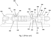
- Fig. 1 illustrates schematically an injection moulding machine 200 as known in the art.
- the injection moulding machine 200 generally comprises an injection unit 210, shown in the left side of the figure, and a clamping unit 270, shown in the right side of the figure.
- the injection unit 210 handles injection of plastic material into a mould formed in the clamping unit 270 of the injection moulding machine 200.
- the injection unit 210 and the clamping unit 270 of the injection moulding machine 200 are attachable to a mount 201.
- the fluid plastic material is fed from the nozzle 225 through sprue channels 226 in a base plate 310 of the mould box 300, and reaches a mould cavity 321 formed in a first mould plate 320 of the mould box 300.
- the first mould plate 320 of the mould box 300 is connected to the base plate 310.
- the base plate 310 is connected to the mount 201.
- a second mould plate 330 which may comprise a mould core and/or further portions of a mould cavity is arranged moveably relative to the first mould plate 320, such that the mould box may be completely closed (clamped together) to allow injection of the melted plastic, and such that the mould box 300 may be opened to extract a moulded item 60 (see Fig. 7 ).
- the second mould plate 330 is attached to a moveable platen 290.
- the moveable platen 290 - and thereby the second mould plate 330 - is slideably arranged on a set of cylindrical main guide rail pillars 400.
- the clamping unit 270 of injection moulding machines 200 comprises four cylindrical main guide rail pillars 400 for guiding the movement of the moveable platen 290 with the second mould plate 330.
- the movement of the moveable platen 290 with the second mould plate 330 is performed by a linear drive mechanism 280, typically a hydraulic mechanism.
- Each of the main guide rail pillars 400 of the main guide rail system of the mould box 300 of the clamping unit 270 has an elongate body, which is cylindrical, and has a first end 443 and a second end 444.
- the first end 443 is fixed to the base plate 310, which is fixed to a frame (not shown) of the clamping unit 270.
- the frame of the clamping unit 270 may form part of the frame 201 of the injection moulding machine 200, or may be fixed thereto.
- the opposite end, the second end 444, of the elongate body of each main guide rail pillars 400 is fixedly connected to a second end structure 315 of the clamping unit 270.
- the second end structure 315 of the clamping unit 270 is fixed to the mount 201 of the clamping unit 270.
- the second end structure 315 may also, as shown in Fig. 1 , form a mount for the linear drive mechanism 280.
- this moveable platen 290 comprises through-going bearings e.g. slide bearings or ball bearings, slidably receiving the cylindrical main guide rail pillars 400.
- the linear drive mechanism 280 clamps the first mould plate 320 and the second mould plate 330 together, whereupon plastic is injected by the reciprocal screw 220 through the nozzle 225 and into the mould cavity 321.
- the linear drive mechanism 280 moves the second mould plate 330 away from the first mould plate 320, and the moulded item 60 is ejected from the mould.
- the ejection of the moulded item 60 is typically done by ejector pins (not shown) formed in/through the base plate 310.
- mould inserts a generally plate shaped structures which are attachable to the mould plates 320, 330 by inserting them there into. Thereby, it is obtained that the often very heavy mould plates do not need to be replaced every time a new type of item is to be injection moulded. Instead only the mould inserts are exchanged.
- the present invention relates to such a mould insert part 1.
- the mould insert part 1 is described in connection with figures 2-8 below. It will be appreciated that the mould insert part 1 described may be used in a mould box 300 as outlined above, in connection with Fig. 1 above. It will further be appreciated that such a mould bow may be implemented in an injection moulding machine 200 as outlined above, in connection with Fig. 1 above.
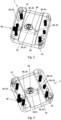
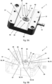
- FIGs. 2-8 fig. 2 and 3 are see-through elevated perspective views, of an embodiment of the mould insert part 1 according to the invention.
- Fig 2 shows the mould insert from one angle.
- Fig. 3 shows the mould insert from a different angle.
- the mould insert part 1 comprises a main body 10, which is a generally plate shaped structure having a first surface 11, and, opposed thereto, a second surface 12.
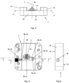
- the first surface 11 defines a plane P, see Fig. 4.
- Fig. 4 shows the mould insert part 1 of Fig. 2 in a side view, where also the first surface 11 and the opposite second surface 12 is visible.
- the first surface 11 faces a second mould insert part with a mould cavity, when both are inserted in/attached to mould plates of a mould box, e.g. as described above.
- the mould insert part 1 comprises a mould core 20 extending outwardly from said first surface 11 of the main body 10. This means that the mould core 20 extends above the plane P.
- the mould insert part 1 is configured for cooperating with a second mould insert part (not shown) having a mould cavity, which is configured for - together with the mould insert part 1 with the mould core 20 - forming a mould for injection moulding an injection moulded item 60.
- the mould insert part 1 is insertable into a mould plate of a mould box, e.g. as exemplified above.
- the second mould insert part with the mould cavity likewise is insertable into another mould plate of a mould box, e.g. as exemplified above.
- the main body 10 of the mould insert part 1 may - as shown - be rectangular or quadratic in shape.
- the main body 10 of the mould insert part 1 - at least in the shown embodiment - further comprises side flanges 13.
- the side flanges 13 are optional.
- the side flanges 13 extend above the first surface 11 of the main body 10 of the mould insert part 1. This means that the side flanges 13 extend above the plane P.
- the side flanges 13 are configured for cooperating with recesses (not shown) on the cooperating second mould insert part (not shown). In the embodiment shown in the Figures 2-8 there are two side flanges 13.
- the mould insert part 1 further comprises a gas inlet port 30.
- the gas inlet port 30 is connectable to a supply of pressurized gas (not shown).
- the pressurized gas may be air.
- the air may be pressurized by a pump (not shown).
- the supply of pressurized gas may be a replaceable pressurized container (not shown).
- the supply of pressurized gas may form part of an injection moulding machine 200, e.g. as described above.
- the supply of pressurized gas may be connected to the gas inlet port 30 by suitable connection tubing configured for conducting pressurized gas and/or conduits formed in the mould plate(s) or other parts of the injection moulding machine 200.
- the gas inlet port 30 is connected to gas outlet ports 40 via a gas conduit system 50.
- a mould insert part 1 according to the invention may comprise more than the gas outlet ports 41, 42 shown in Figs.2-8 , such as 3-20 gas outlet ports 40.
- Each of the two or more gas outlet ports 41, 42 are arranged at least partially through the first surface 11.
- the gas conduit system 50 comprises a first conduit 51 extending from the gas inlet port 30 to the first gas outlet port 41.
- the gas conduit system 50 further comprises a second conduit 52 extending from the gas inlet port 30 to the second gas outlet port 40.
- the first and second conduits 51, 52 branches of from each other in close vicinity of the gas inlet port 30.
- the gas conduit system 50 may comprise intermediate conduit sections and/or branching off of conduits at other locations.
- the gas conduit system 50 may comprises a common gas conduit 55, extending from the gas inlet port 30, and which branches into sub-conduits 56, which sub-conduits 56 connect to the gas outlet ports 40.
- the gas inlet port 30 may also be provided below said first surface 11. This means that the gas inlet port 30 is provided below the plane P.
- the mould insert part 1 may - in not shown embodiments comprise more than the two gas outlet ports 41, 42 shown in Figs. 2-8 , such as 3-20 gas outlet ports 40.
- the plurality of gas outlet ports 40 surrounds the mould core 20.
- the plurality of gas outlet ports 40 are equidistantly spaced apart.
- the plurality of gas outlet ports 40 are formed in a circle surrounding the mould core 20, as exemplified in the Fig. 9A-C embodiment.
- all of the gas outlet ports 40 may be of the type designated with the reference number 41 in the Fig. 2-8 embodiment, i.e. where a first gas outlet port 41 is arranged fully in and through first surface 11 of the main body 10.
- some or all of the gas outlet ports 40 may be of the type designated with the reference number 42 in connection with the Fig. 2-8 embodiment, i.e. where a second gas outlet ports 42 is arranged in an intersection between the first surface 11 of the main body 10, and one of the side flanges 13
- the first gas conduit 51 is formed such that it at least partially extends under the mould core 20 of the mould insert part 1.
- the mould insert part 1 may further comprise an injection channel 70 for injecting molten plastic into the mould.
- the injection channel 70 is arranged centrally through the mould core 20.
- an injection channel 70 may be arranged at other positions relative to the mould core, and in some cases, there may be more than one injection channel 70 (not shown).
- the gas conduits of the gas conduit system 50 necessarily must avoid such structures such as the injection channel 70 and for example passageways for ejector pins and the like. However, it has been realized that some gas conduits 50 may extend very close to and even under the core to save space in the mould insert part 1.
- the mould core 20 may comprise a centreline C.
- two or more gas outlet ports 40, 41, 42 are further configured to direct gas towards the centreline C of the core 20. As shown in Fig. 5 this is the case with the Figs. 2-8 embodiment. It is also the case in the Fig. 9A-C embodiment.
- each gas outlet port 40 is preferably configured to blow gas onto a desired area of the free outer surface 61 of the injection moulded item, and predetermined dependent on the shape of the injection moulded item 60.
- All of the gas outlet ports 40 may have the same angle relative to the plane P. In other embodiments, each gas outlet port 40 may be formed at angles relative to the plane, which are different from the other gas outlet ports 40.
- connection stud 31 In the embodiment shown in Figs 9A-C , the gas inlet port 30 shown with a connection stud 31. It will be appreciated that also the embodiment of Figs. 2-8 may be equipped with such a connection stud.
- mould insert part 1 according to the invention is formed in an additive manufacturing process, such as 3D printing, and in a polymer material, e.g. a plastic, it is easier to shape complexly shaped gas conduits.
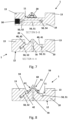
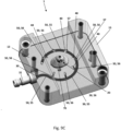
- the mould insertion part 501 in Fig. 10A is illustrated as a mould insertion part 501 with a mould cavity 580.
- the mould cavity 580 shown is as such unrelated to the mould core 20 shown in connection with Figs. 2-9 .
- the mould insert part 501 is configured for cooperating with a mould insertion part with a mould core (not shown), where the mould core is configured to cooperate with the mould cavity to form an injection moulded item (not shown).
- the mould cavity 580 has an elongate cylindrical shape configured to form an elongate cylindrical item.
- the mould insert part 501 comprises a main body 510, which is a generally plate shaped structure having a first surface 511, and, opposed thereto, a second surface 512.
- the mould insert part 501 comprises a mould core cavity 580 extending inwardly from said first surface 511 of the main body 510. This means that the mould core 20 extends below the plane P2.
- the mould insert part 501 is insertable into a mould plate of a mould box, e.g. as exemplified above.
- the second mould insert part with the mould core likewise is insertable into another mould plate of a mould box, e.g. as exemplified above.
- the main body 510 of the mould insert part 501 may - as shown - be rectangular or quadratic in shape.
- the mould insert part 501 may be configured to cooperate with a mould insert part 1 (having a mould core 20) as described above, but where the mould core and the mold cavity of the respective mould insert parts are adapted to cooperate.
- the mould insert part 501 may be configured for cooperating with a more conventional type of mould insert part with a core.
- Fig. 10B shows a section A-A through the mould insert part 501 as indicated in Fig. 10A .
- the side sectional view in Fig. 10B reveals that the mould insert part 501 comprises an injection channel 570 for injecting molten plastic into the mould.
- the injection channel 570 is arranged centrally through the mould insert part 501 and may interface with further channels/runners of cavity portions in the cooperating mould insert part to fill the mould cavity 580.
- the venting conduit 590 forms an air vents configured for allowing air to escape from the mould cavity 580 as the mould cavity 580 is filled with melted material.
- the mould insert part 501 according to the invention is 3D printed in plastic. Thereby, it is easier to shape complexly formed air vents 590.
- the restriction hole is so small that it prevents molten plastic to exit the mould cavity 580, while still allowing the air otherwise trapped in the mould cavity 580 to escape.
Landscapes
- Engineering & Computer Science (AREA)
- Mechanical Engineering (AREA)
- Manufacturing & Machinery (AREA)
- Physics & Mathematics (AREA)
- Fluid Mechanics (AREA)
- Moulds For Moulding Plastics Or The Like (AREA)
- Injection Moulding Of Plastics Or The Like (AREA)
Claims (9)
- Formeinsatzteil (1) für Spritzguss, umfassend- einen Hauptkörper (10), der eine erste Fläche (11) und eine gegenüberliegende zweite Fläche (12) aufweist, wobei die erste Fläche eine Ebene (P) definiert,- einen Formkern (20), der sich von der ersten Fläche (11) des Hauptkörpers (10) des Formeinsatzteils (1) erstreckt;- einen Gaseinlassanschluss (30), der mit einer Druckgaszufuhr verbunden werden kann;- zwei oder mehr Gasauslassanschlüsse (40), die so angeordnet sind, dass sie einen Gasstrom zu einer unbedeckten Fläche (61) eines Spritzgussartikels (60), der sich auf dem Formkern (20) befindet, hin lenken, nachdem der Formkern (20) und der Formhohlraum voneinander getrennt wurden; und- ein Gasleitungssystem (50), das sich innerhalb des Hauptkörpers (10) des Formeinsatzteils (1) erstreckt und die zwei oder die mehreren Gasauslassanschlüsse (40) mit dem Gaseinlassanschluss (30), der den zwei oder den mehreren Gasauslassanschlüssen (40) gemeinsam ist, verbindet,wobei jeder der zwei oder der mehreren Gasauslassanschlüsse (40) mindestens teilweise durch die erste Fläche (11) hindurch angeordnet ist, undwobei das Gasleitungssystem (50) im Hauptkörper (10) unterhalb der ersten Fläche (11) bereitgestellt ist.
- Formeinsatzteil (1) nach Anspruch 1, wobei mindestens zwei der zwei oder der mehreren Gasauslassanschlüsse auf gegenüberliegenden Seiten des Formkerns (20) angeordnet sind.
- Formeinsatzteil (1) nach Anspruch 1 oder 2, wobei mindestens eine Gasleitung (51) des Gasleitungssystems (50) eine Biegung (53, 57) von 90° oder mehr aufweist.
- Formeinsatzteil (1) nach einem der Ansprüche 1-3, wobei sich mindestens eine Gasleitung (51) mindestens teilweise unter dem Formkern (20) des Formeinsatzteils (1) erstreckt.
- Formeinsatzteil (1) nach einem der Ansprüche 1-4, wobei die zwei oder die mehreren Gasauslassanschlüsse (40, 41, 42) weiter so konfiguriert sind, dass sie Gas zu einer Mittellinie (C) des Formkerns (20) hin lenken.
- Formeinsatzteil (1) nach einem der Ansprüche 1-5, wobei jeder der zwei oder der mehreren Gasauslassanschlüsse (40, 41, 42) so konfiguriert ist, dass er das Gas in einem Winkel relativ zu der durch die erste Fläche (11) definierten Ebene (P) lenkt, und wobei der Winkel größer als 0° und kleiner als 90° ist.
- Formeinsatzteil (1) nach einem der Ansprüche 1-6, wobei das Formeinsatzteil (1) in einem additiven Fertigungsprozess gebildet wird.
- Kombination aus einem Formkasten für eine Spritzgussmaschine und einem Formeinsatzteil (1) nach einem der Ansprüche 1-7, wobei der Formkasten umfasst- ein erstes Formteil; und- ein zweites Formteil,wobei das Formeinsatzteil (1) in eines des ersten oder des zweiten Formteils eingesetzt werden kann, und wobei ein zweiter Formeinsatz, der einen dem Formkern (20) entsprechenden Formhohlraum aufweist, um einen Spritzgussartikel (60) zu bilden, in das andere des ersten oder des zweiten Formteils einsetzbar ist, um eine Form zu bilden.
- Spritzgussmaschine, die eine Kombination nach Anspruch 8 umfasst.
Applications Claiming Priority (2)
| Application Number | Priority Date | Filing Date | Title |
|---|---|---|---|
| DKPA202170395 | 2021-08-02 | ||
| PCT/EP2022/071669 WO2023012150A1 (en) | 2021-08-02 | 2022-08-02 | Mould insert with conduits for cooling injection moulded item |
Publications (2)
| Publication Number | Publication Date |
|---|---|
| EP4380774A1 EP4380774A1 (de) | 2024-06-12 |
| EP4380774B1 true EP4380774B1 (de) | 2025-06-25 |
Family
ID=83152161
Family Applications (1)
| Application Number | Title | Priority Date | Filing Date |
|---|---|---|---|
| EP22761959.0A Active EP4380774B1 (de) | 2021-08-02 | 2022-08-02 | Formeinsatz mit leitungen zum kühlen eines spritzgegossenen artikels |
Country Status (5)
| Country | Link |
|---|---|
| US (1) | US20240342971A1 (de) |
| EP (1) | EP4380774B1 (de) |
| CN (1) | CN117642267A (de) |
| DK (1) | DK4380774T3 (de) |
| WO (1) | WO2023012150A1 (de) |
Citations (4)
| Publication number | Priority date | Publication date | Assignee | Title |
|---|---|---|---|---|
| JPS6225020A (ja) * | 1985-07-25 | 1987-02-03 | Matsushita Electric Works Ltd | 光デイスクの製法およびその実施に用いる装置 |
| WO2004048207A2 (de) * | 2002-11-22 | 2004-06-10 | Transcoject Gmbh & Co. Kg. | Verfahren zur herstellung und/oder handhabung eines hochreinen gegenstandes |
| US20160107357A1 (en) * | 2014-10-17 | 2016-04-21 | Quanta Computer Inc. | Molding system and method for directly gas-cooling a molding object |
| EP3459703A1 (de) * | 2017-09-26 | 2019-03-27 | Brandon Fontaine | Spritzgiessanordnung mit kühleinsatz |
Family Cites Families (3)
| Publication number | Priority date | Publication date | Assignee | Title |
|---|---|---|---|---|
| JPS6475218A (en) * | 1987-09-18 | 1989-03-20 | Sanri Kk | Injection method of air flow to mold and its device in injection molding machine |
| JPH03256707A (ja) * | 1990-03-07 | 1991-11-15 | Japan Electron Control Syst Co Ltd | 成形金型装置 |
| FR3067966B1 (fr) * | 2017-06-23 | 2019-08-02 | Valeo Vision | Procede de moulage d'une piece optique avec refroidissement direct de la piece par un fluide |
-
2022
- 2022-08-02 WO PCT/EP2022/071669 patent/WO2023012150A1/en not_active Ceased
- 2022-08-02 CN CN202280048977.3A patent/CN117642267A/zh active Pending
- 2022-08-02 US US18/294,505 patent/US20240342971A1/en active Pending
- 2022-08-02 DK DK22761959.0T patent/DK4380774T3/da active
- 2022-08-02 EP EP22761959.0A patent/EP4380774B1/de active Active
Patent Citations (4)
| Publication number | Priority date | Publication date | Assignee | Title |
|---|---|---|---|---|
| JPS6225020A (ja) * | 1985-07-25 | 1987-02-03 | Matsushita Electric Works Ltd | 光デイスクの製法およびその実施に用いる装置 |
| WO2004048207A2 (de) * | 2002-11-22 | 2004-06-10 | Transcoject Gmbh & Co. Kg. | Verfahren zur herstellung und/oder handhabung eines hochreinen gegenstandes |
| US20160107357A1 (en) * | 2014-10-17 | 2016-04-21 | Quanta Computer Inc. | Molding system and method for directly gas-cooling a molding object |
| EP3459703A1 (de) * | 2017-09-26 | 2019-03-27 | Brandon Fontaine | Spritzgiessanordnung mit kühleinsatz |
Also Published As
| Publication number | Publication date |
|---|---|
| EP4380774A1 (de) | 2024-06-12 |
| CN117642267A (zh) | 2024-03-01 |
| WO2023012150A1 (en) | 2023-02-09 |
| US20240342971A1 (en) | 2024-10-17 |
| DK4380774T3 (da) | 2025-09-22 |
Similar Documents
| Publication | Publication Date | Title |
|---|---|---|
| US10442125B2 (en) | Injection mold, molding tool comprising the mold and methods of use thereof | |
| KR100704045B1 (ko) | 나선형 홈을 갖는 사출 성형 냉각 코어 | |
| KR101697172B1 (ko) | 플라스틱의 성형방법 | |
| CN102497968A (zh) | 用于预制件的后处理及传递的系统 | |
| CN216465971U (zh) | 一种模内裁切注塑模具 | |
| KR101191231B1 (ko) | 사출 성형 금형 | |
| CN105050790B (zh) | 具有浮动腔插件的模具堆叠 | |
| CN101774259B (zh) | 成型模具 | |
| EP4380774B1 (de) | Formeinsatz mit leitungen zum kühlen eines spritzgegossenen artikels | |
| KR20100008869A (ko) | 핫 러너 시스템 및 이를 이용한 사출 성형 방법 | |
| US6652263B2 (en) | Ingate arrangement for an injection mold | |
| US20130209603A1 (en) | Injection molding machine | |
| CN113977878A (zh) | 一种模内裁切注塑模具及其使用方法 | |
| CN105658399B (zh) | 注射成型和组装设备以及将多个两种不同模制部件成型和组装的方法 | |
| CN217944154U (zh) | 一种应用于多穴位的模仁总成 | |
| CN216329724U (zh) | 一种注塑模具及注塑系统 | |
| AU2005294075A1 (en) | Multiple-level stack mold apparatus | |
| KR101189111B1 (ko) | 사출 성형 금형 | |
| CN212194163U (zh) | 一种注吹成型装置 | |
| JP4789645B2 (ja) | 樹脂成形品の製造方法及び製造装置 | |
| CA2607310A1 (en) | A robot for an injection molding system | |
| EP4100225B1 (de) | Spritzgiessmaschine mit einem führungsschienensystem für einen formwerkzeugaufbau | |
| FI111917B (fi) | Ruiskuvalumuotti ja ruiskuvalukoneen suutin | |
| EP1927456A1 (de) | Formvorrichtung zum formen eines blasgeformten produkts und verfahren zum formen eines blasgeformten produkts | |
| JPH08118435A (ja) | 射出成形金型 |
Legal Events
| Date | Code | Title | Description |
|---|---|---|---|
| STAA | Information on the status of an ep patent application or granted ep patent |
Free format text: STATUS: UNKNOWN |
|
| STAA | Information on the status of an ep patent application or granted ep patent |
Free format text: STATUS: THE INTERNATIONAL PUBLICATION HAS BEEN MADE |
|
| PUAI | Public reference made under article 153(3) epc to a published international application that has entered the european phase |
Free format text: ORIGINAL CODE: 0009012 |
|
| STAA | Information on the status of an ep patent application or granted ep patent |
Free format text: STATUS: REQUEST FOR EXAMINATION WAS MADE |
|
| 17P | Request for examination filed |
Effective date: 20240212 |
|
| AK | Designated contracting states |
Kind code of ref document: A1 Designated state(s): AL AT BE BG CH CY CZ DE DK EE ES FI FR GB GR HR HU IE IS IT LI LT LU LV MC MK MT NL NO PL PT RO RS SE SI SK SM TR |
|
| DAV | Request for validation of the european patent (deleted) | ||
| DAX | Request for extension of the european patent (deleted) | ||
| P01 | Opt-out of the competence of the unified patent court (upc) registered |
Free format text: CASE NUMBER: APP_58985/2024 Effective date: 20241031 |
|
| GRAP | Despatch of communication of intention to grant a patent |
Free format text: ORIGINAL CODE: EPIDOSNIGR1 |
|
| STAA | Information on the status of an ep patent application or granted ep patent |
Free format text: STATUS: GRANT OF PATENT IS INTENDED |
|
| INTG | Intention to grant announced |
Effective date: 20250127 |
|
| GRAS | Grant fee paid |
Free format text: ORIGINAL CODE: EPIDOSNIGR3 |
|
| GRAA | (expected) grant |
Free format text: ORIGINAL CODE: 0009210 |
|
| STAA | Information on the status of an ep patent application or granted ep patent |
Free format text: STATUS: THE PATENT HAS BEEN GRANTED |
|
| AK | Designated contracting states |
Kind code of ref document: B1 Designated state(s): AL AT BE BG CH CY CZ DE DK EE ES FI FR GB GR HR HU IE IS IT LI LT LU LV MC MK MT NL NO PL PT RO RS SE SI SK SM TR |
|
| REG | Reference to a national code |
Ref country code: GB Ref legal event code: FG4D |
|
| REG | Reference to a national code |
Ref country code: CH Ref legal event code: EP |
|
| REG | Reference to a national code |
Ref country code: DE Ref legal event code: R096 Ref document number: 602022016545 Country of ref document: DE |
|
| REG | Reference to a national code |
Ref country code: CH Ref legal event code: EP |
|
| REG | Reference to a national code |
Ref country code: IE Ref legal event code: FG4D |
|
| REG | Reference to a national code |
Ref country code: DK Ref legal event code: T3 Effective date: 20250915 |
|
| PG25 | Lapsed in a contracting state [announced via postgrant information from national office to epo] |
Ref country code: FI Free format text: LAPSE BECAUSE OF FAILURE TO SUBMIT A TRANSLATION OF THE DESCRIPTION OR TO PAY THE FEE WITHIN THE PRESCRIBED TIME-LIMIT Effective date: 20250625 |
|
| PGFP | Annual fee paid to national office [announced via postgrant information from national office to epo] |
Ref country code: DE Payment date: 20250820 Year of fee payment: 4 Ref country code: DK Payment date: 20250926 Year of fee payment: 4 |
|
| REG | Reference to a national code |
Ref country code: LT Ref legal event code: MG9D |
|
| PG25 | Lapsed in a contracting state [announced via postgrant information from national office to epo] |
Ref country code: NO Free format text: LAPSE BECAUSE OF FAILURE TO SUBMIT A TRANSLATION OF THE DESCRIPTION OR TO PAY THE FEE WITHIN THE PRESCRIBED TIME-LIMIT Effective date: 20250925 Ref country code: GR Free format text: LAPSE BECAUSE OF FAILURE TO SUBMIT A TRANSLATION OF THE DESCRIPTION OR TO PAY THE FEE WITHIN THE PRESCRIBED TIME-LIMIT Effective date: 20250926 |
|
| PG25 | Lapsed in a contracting state [announced via postgrant information from national office to epo] |
Ref country code: BG Free format text: LAPSE BECAUSE OF FAILURE TO SUBMIT A TRANSLATION OF THE DESCRIPTION OR TO PAY THE FEE WITHIN THE PRESCRIBED TIME-LIMIT Effective date: 20250625 |
|
| PG25 | Lapsed in a contracting state [announced via postgrant information from national office to epo] |
Ref country code: HR Free format text: LAPSE BECAUSE OF FAILURE TO SUBMIT A TRANSLATION OF THE DESCRIPTION OR TO PAY THE FEE WITHIN THE PRESCRIBED TIME-LIMIT Effective date: 20250625 |
|
| PGFP | Annual fee paid to national office [announced via postgrant information from national office to epo] |
Ref country code: AT Payment date: 20251020 Year of fee payment: 4 |
|
| PG25 | Lapsed in a contracting state [announced via postgrant information from national office to epo] |
Ref country code: RS Free format text: LAPSE BECAUSE OF FAILURE TO SUBMIT A TRANSLATION OF THE DESCRIPTION OR TO PAY THE FEE WITHIN THE PRESCRIBED TIME-LIMIT Effective date: 20250925 |
|
| PG25 | Lapsed in a contracting state [announced via postgrant information from national office to epo] |
Ref country code: LV Free format text: LAPSE BECAUSE OF FAILURE TO SUBMIT A TRANSLATION OF THE DESCRIPTION OR TO PAY THE FEE WITHIN THE PRESCRIBED TIME-LIMIT Effective date: 20250625 |
|
| REG | Reference to a national code |
Ref country code: NL Ref legal event code: MP Effective date: 20250625 |
|
| PG25 | Lapsed in a contracting state [announced via postgrant information from national office to epo] |
Ref country code: NL Free format text: LAPSE BECAUSE OF FAILURE TO SUBMIT A TRANSLATION OF THE DESCRIPTION OR TO PAY THE FEE WITHIN THE PRESCRIBED TIME-LIMIT Effective date: 20250625 |
|
| PG25 | Lapsed in a contracting state [announced via postgrant information from national office to epo] |
Ref country code: PT Free format text: LAPSE BECAUSE OF FAILURE TO SUBMIT A TRANSLATION OF THE DESCRIPTION OR TO PAY THE FEE WITHIN THE PRESCRIBED TIME-LIMIT Effective date: 20251027 |
|
| REG | Reference to a national code |
Ref country code: AT Ref legal event code: MK05 Ref document number: 1806034 Country of ref document: AT Kind code of ref document: T Effective date: 20250625 |
|
| PG25 | Lapsed in a contracting state [announced via postgrant information from national office to epo] |
Ref country code: IS Free format text: LAPSE BECAUSE OF FAILURE TO SUBMIT A TRANSLATION OF THE DESCRIPTION OR TO PAY THE FEE WITHIN THE PRESCRIBED TIME-LIMIT Effective date: 20251025 |
|
| PG25 | Lapsed in a contracting state [announced via postgrant information from national office to epo] |
Ref country code: AT Free format text: LAPSE BECAUSE OF FAILURE TO SUBMIT A TRANSLATION OF THE DESCRIPTION OR TO PAY THE FEE WITHIN THE PRESCRIBED TIME-LIMIT Effective date: 20250625 Ref country code: SM Free format text: LAPSE BECAUSE OF FAILURE TO SUBMIT A TRANSLATION OF THE DESCRIPTION OR TO PAY THE FEE WITHIN THE PRESCRIBED TIME-LIMIT Effective date: 20250625 |
|
| PG25 | Lapsed in a contracting state [announced via postgrant information from national office to epo] |
Ref country code: CZ Free format text: LAPSE BECAUSE OF FAILURE TO SUBMIT A TRANSLATION OF THE DESCRIPTION OR TO PAY THE FEE WITHIN THE PRESCRIBED TIME-LIMIT Effective date: 20250625 |
|
| PG25 | Lapsed in a contracting state [announced via postgrant information from national office to epo] |
Ref country code: PL Free format text: LAPSE BECAUSE OF FAILURE TO SUBMIT A TRANSLATION OF THE DESCRIPTION OR TO PAY THE FEE WITHIN THE PRESCRIBED TIME-LIMIT Effective date: 20250625 |
|
| PG25 | Lapsed in a contracting state [announced via postgrant information from national office to epo] |
Ref country code: EE Free format text: LAPSE BECAUSE OF FAILURE TO SUBMIT A TRANSLATION OF THE DESCRIPTION OR TO PAY THE FEE WITHIN THE PRESCRIBED TIME-LIMIT Effective date: 20250625 |
|
| PG25 | Lapsed in a contracting state [announced via postgrant information from national office to epo] |
Ref country code: SK Free format text: LAPSE BECAUSE OF FAILURE TO SUBMIT A TRANSLATION OF THE DESCRIPTION OR TO PAY THE FEE WITHIN THE PRESCRIBED TIME-LIMIT Effective date: 20250625 |
|
| PG25 | Lapsed in a contracting state [announced via postgrant information from national office to epo] |
Ref country code: ES Free format text: LAPSE BECAUSE OF FAILURE TO SUBMIT A TRANSLATION OF THE DESCRIPTION OR TO PAY THE FEE WITHIN THE PRESCRIBED TIME-LIMIT Effective date: 20250625 |
|
| PG25 | Lapsed in a contracting state [announced via postgrant information from national office to epo] |
Ref country code: RO Free format text: LAPSE BECAUSE OF FAILURE TO SUBMIT A TRANSLATION OF THE DESCRIPTION OR TO PAY THE FEE WITHIN THE PRESCRIBED TIME-LIMIT Effective date: 20250625 |
|
| REG | Reference to a national code |
Ref country code: CH Ref legal event code: H13 Free format text: ST27 STATUS EVENT CODE: U-0-0-H10-H13 (AS PROVIDED BY THE NATIONAL OFFICE) Effective date: 20260324 |
|
| PG25 | Lapsed in a contracting state [announced via postgrant information from national office to epo] |
Ref country code: MC Free format text: LAPSE BECAUSE OF FAILURE TO SUBMIT A TRANSLATION OF THE DESCRIPTION OR TO PAY THE FEE WITHIN THE PRESCRIBED TIME-LIMIT Effective date: 20250625 |
|
| PG25 | Lapsed in a contracting state [announced via postgrant information from national office to epo] |
Ref country code: LU Free format text: LAPSE BECAUSE OF NON-PAYMENT OF DUE FEES Effective date: 20250802 Ref country code: IT Free format text: LAPSE BECAUSE OF FAILURE TO SUBMIT A TRANSLATION OF THE DESCRIPTION OR TO PAY THE FEE WITHIN THE PRESCRIBED TIME-LIMIT Effective date: 20250625 |