EP4378650A1 - Method for producing osb and osb production device - Google Patents
Method for producing osb and osb production device Download PDFInfo
- Publication number
- EP4378650A1 EP4378650A1 EP22211013.2A EP22211013A EP4378650A1 EP 4378650 A1 EP4378650 A1 EP 4378650A1 EP 22211013 A EP22211013 A EP 22211013A EP 4378650 A1 EP4378650 A1 EP 4378650A1
- Authority
- EP
- European Patent Office
- Prior art keywords
- flame retardant
- layer
- chips
- osb
- chip
- Prior art date
- Legal status (The legal status is an assumption and is not a legal conclusion. Google has not performed a legal analysis and makes no representation as to the accuracy of the status listed.)
- Pending
Links
- 238000004519 manufacturing process Methods 0.000 title claims abstract description 49
- 239000003063 flame retardant Substances 0.000 claims abstract description 188
- RNFJDJUURJAICM-UHFFFAOYSA-N 2,2,4,4,6,6-hexaphenoxy-1,3,5-triaza-2$l^{5},4$l^{5},6$l^{5}-triphosphacyclohexa-1,3,5-triene Chemical compound N=1P(OC=2C=CC=CC=2)(OC=2C=CC=CC=2)=NP(OC=2C=CC=CC=2)(OC=2C=CC=CC=2)=NP=1(OC=1C=CC=CC=1)OC1=CC=CC=C1 RNFJDJUURJAICM-UHFFFAOYSA-N 0.000 claims abstract description 181
- 239000007788 liquid Substances 0.000 claims abstract description 89
- 238000003825 pressing Methods 0.000 claims abstract description 12
- 239000003292 glue Substances 0.000 claims abstract description 11
- 238000009826 distribution Methods 0.000 claims description 59
- 239000000463 material Substances 0.000 claims description 18
- 238000000034 method Methods 0.000 claims description 17
- 239000002023 wood Substances 0.000 claims description 12
- 238000007689 inspection Methods 0.000 claims description 11
- 238000001035 drying Methods 0.000 claims description 6
- 239000003638 chemical reducing agent Substances 0.000 claims description 3
- 239000004094 surface-active agent Substances 0.000 claims description 2
- 239000002245 particle Substances 0.000 claims 4
- 230000003247 decreasing effect Effects 0.000 claims 2
- 230000001419 dependent effect Effects 0.000 claims 1
- 238000001514 detection method Methods 0.000 claims 1
- 230000003287 optical effect Effects 0.000 claims 1
- 239000002904 solvent Substances 0.000 description 10
- XLYOFNOQVPJJNP-UHFFFAOYSA-N water Substances O XLYOFNOQVPJJNP-UHFFFAOYSA-N 0.000 description 9
- 238000004026 adhesive bonding Methods 0.000 description 7
- 239000002184 metal Substances 0.000 description 4
- 238000005520 cutting process Methods 0.000 description 3
- 238000012360 testing method Methods 0.000 description 3
- 239000011093 chipboard Substances 0.000 description 2
- 230000007423 decrease Effects 0.000 description 2
- 230000001678 irradiating effect Effects 0.000 description 2
- 230000001105 regulatory effect Effects 0.000 description 2
- 238000005507 spraying Methods 0.000 description 2
- 239000004753 textile Substances 0.000 description 2
- 238000011144 upstream manufacturing Methods 0.000 description 2
- OAICVXFJPJFONN-UHFFFAOYSA-N Phosphorus Chemical compound [P] OAICVXFJPJFONN-UHFFFAOYSA-N 0.000 description 1
- 238000005299 abrasion Methods 0.000 description 1
- 238000013459 approach Methods 0.000 description 1
- 239000007864 aqueous solution Substances 0.000 description 1
- 230000009286 beneficial effect Effects 0.000 description 1
- 230000033228 biological regulation Effects 0.000 description 1
- 238000006243 chemical reaction Methods 0.000 description 1
- 238000001816 cooling Methods 0.000 description 1
- 239000006185 dispersion Substances 0.000 description 1
- 239000013013 elastic material Substances 0.000 description 1
- 239000000839 emulsion Substances 0.000 description 1
- 230000001815 facial effect Effects 0.000 description 1
- 238000010438 heat treatment Methods 0.000 description 1
- 239000007791 liquid phase Substances 0.000 description 1
- 239000003550 marker Substances 0.000 description 1
- 238000005259 measurement Methods 0.000 description 1
- -1 nitrogen-containing compound Chemical class 0.000 description 1
- 229910052698 phosphorus Inorganic materials 0.000 description 1
- 239000011574 phosphorus Substances 0.000 description 1
- 238000012545 processing Methods 0.000 description 1
- 230000005855 radiation Effects 0.000 description 1
- 230000035484 reaction time Effects 0.000 description 1
- 239000007787 solid Substances 0.000 description 1
- 239000000243 solution Substances 0.000 description 1
- 239000007921 spray Substances 0.000 description 1
Images


Classifications
-
- B—PERFORMING OPERATIONS; TRANSPORTING
- B27—WORKING OR PRESERVING WOOD OR SIMILAR MATERIAL; NAILING OR STAPLING MACHINES IN GENERAL
- B27N—MANUFACTURE BY DRY PROCESSES OF ARTICLES, WITH OR WITHOUT ORGANIC BINDING AGENTS, MADE FROM PARTICLES OR FIBRES CONSISTING OF WOOD OR OTHER LIGNOCELLULOSIC OR LIKE ORGANIC MATERIAL
- B27N1/00—Pretreatment of moulding material
- B27N1/02—Mixing the material with binding agent
- B27N1/029—Feeding; Proportioning; Controlling
-
- B—PERFORMING OPERATIONS; TRANSPORTING
- B27—WORKING OR PRESERVING WOOD OR SIMILAR MATERIAL; NAILING OR STAPLING MACHINES IN GENERAL
- B27N—MANUFACTURE BY DRY PROCESSES OF ARTICLES, WITH OR WITHOUT ORGANIC BINDING AGENTS, MADE FROM PARTICLES OR FIBRES CONSISTING OF WOOD OR OTHER LIGNOCELLULOSIC OR LIKE ORGANIC MATERIAL
- B27N3/00—Manufacture of substantially flat articles, e.g. boards, from particles or fibres
- B27N3/02—Manufacture of substantially flat articles, e.g. boards, from particles or fibres from particles
-
- B—PERFORMING OPERATIONS; TRANSPORTING
- B27—WORKING OR PRESERVING WOOD OR SIMILAR MATERIAL; NAILING OR STAPLING MACHINES IN GENERAL
- B27N—MANUFACTURE BY DRY PROCESSES OF ARTICLES, WITH OR WITHOUT ORGANIC BINDING AGENTS, MADE FROM PARTICLES OR FIBRES CONSISTING OF WOOD OR OTHER LIGNOCELLULOSIC OR LIKE ORGANIC MATERIAL
- B27N3/00—Manufacture of substantially flat articles, e.g. boards, from particles or fibres
- B27N3/08—Moulding or pressing
- B27N3/10—Moulding of mats
- B27N3/14—Distributing or orienting the particles or fibres
-
- B—PERFORMING OPERATIONS; TRANSPORTING
- B27—WORKING OR PRESERVING WOOD OR SIMILAR MATERIAL; NAILING OR STAPLING MACHINES IN GENERAL
- B27N—MANUFACTURE BY DRY PROCESSES OF ARTICLES, WITH OR WITHOUT ORGANIC BINDING AGENTS, MADE FROM PARTICLES OR FIBRES CONSISTING OF WOOD OR OTHER LIGNOCELLULOSIC OR LIKE ORGANIC MATERIAL
- B27N3/00—Manufacture of substantially flat articles, e.g. boards, from particles or fibres
- B27N3/08—Moulding or pressing
- B27N3/18—Auxiliary operations, e.g. preheating, humidifying, cutting-off
-
- B—PERFORMING OPERATIONS; TRANSPORTING
- B27—WORKING OR PRESERVING WOOD OR SIMILAR MATERIAL; NAILING OR STAPLING MACHINES IN GENERAL
- B27N—MANUFACTURE BY DRY PROCESSES OF ARTICLES, WITH OR WITHOUT ORGANIC BINDING AGENTS, MADE FROM PARTICLES OR FIBRES CONSISTING OF WOOD OR OTHER LIGNOCELLULOSIC OR LIKE ORGANIC MATERIAL
- B27N9/00—Arrangements for fireproofing
-
- B—PERFORMING OPERATIONS; TRANSPORTING
- B27—WORKING OR PRESERVING WOOD OR SIMILAR MATERIAL; NAILING OR STAPLING MACHINES IN GENERAL
- B27N—MANUFACTURE BY DRY PROCESSES OF ARTICLES, WITH OR WITHOUT ORGANIC BINDING AGENTS, MADE FROM PARTICLES OR FIBRES CONSISTING OF WOOD OR OTHER LIGNOCELLULOSIC OR LIKE ORGANIC MATERIAL
- B27N1/00—Pretreatment of moulding material
- B27N1/02—Mixing the material with binding agent
- B27N1/0218—Mixing the material with binding agent in rotating drums
Definitions
- the invention relates to a method for producing, in particular, flame-retardant OSB (oriented strand board), which can also be referred to as chipboard.
- OSB oriented strand board
- flame retardants themselves are expensive.
- flame retardants mean that more glue has to be used to achieve the same mechanical strength as a non-flame-retardant OSB board, which is also undesirable.
- most flame retardants are poorly soluble in water, so that introducing the flame retardant into the chips also introduces large amounts of water, which often have to be removed during further processing.
- the invention is based on the object of improving the production of flame-retardant wood-based panels, in particular OSB.
- the invention solves the problem by a method for producing OSB with the steps (a) producing coarse chips, (b) applying glue to the coarse chips so that glued coarse chips are formed, (c) arranging the glued coarse chips on a conveyor belt so that a chip layer is formed, (d) applying a flame retardant liquid to this chip layer and (e) pressing the chip layer so that the OSB board is formed.
- the invention solves the problem of a method for producing wood-based panels with the steps (a) producing chips, (b) applying glue to the chips so that glued chips are produced, (c) arranging the glued chips on a conveyor belt so that a chip layer is produced, (d) applying a flame retardant liquid to this chip layer and (e) pressing the chip layer so that the wood-based panel is produced.
- coarse chips are mentioned below, normal chips that are not coarse chips are also meant within the scope of this most general form of the invention.
- the invention solves the problem by a generic OSB manufacturing device which has (a) a first flame retardant liquid application device which is arranged to apply a flame retardant liquid to the first cover layer, and (b) a second flame retardant liquid application device which is arranged to apply a flame retardant liquid to the second cover layer.
- the invention solves the problem by a wood-based panel manufacturing device with (a) a chip manufacturing device for producing chips from wood, (b) a dryer for drying the chips, which is connected to the coarse chip manufacturing device, (c) a belt conveyor arranged behind the dryer in the material flow direction, (d) a first distribution device for distributing chips on the belt conveyor so that a first cover layer is formed, (e) a second distribution device for distributing chips so that a second cover layer is formed above the first cover layer so that a chip layer is formed (d) a press for pressing the chip layer into an OSB board, (e) a first flame retardant liquid application device arranged to apply a flame retardant liquid to the first cover layer, and (d) a second flame retardant liquid application device, which is arranged to apply a flame retardant liquid to the second cover layer.
- OSB Japanese Industrial Standard
- wood-based panels are generally meant within the scope of this most general form of the invention; when a coarse chip production device is mentioned, a chip production device is generally
- this distance is less than 30 m. This reduces the amount of OSB that has a sufficiently high flame retardant content, particularly when starting up or changing to the production of flame-retardant OSB. In this way, flame-retardant OSB and non-OSB can also be produced using the same OSB production device. Furthermore, the reaction time between glue and flame retardant or the water in the flame retardant is shortened.
- coarse chips are understood to mean in particular wood chips which are in the size range 200 ⁇ 30 cm x 20 ⁇ 4 cm x 0.5 ⁇ 0.2 cm.
- the flame retardant liquid is preferably an aqueous solution.
- the flame retardant liquid preferably contains at least one organic or inorganic phosphorus-containing and/or nitrogen-containing compound.
- the flame retardant is preferably boron-free.
- Pressing is understood to mean pressing using a belt press.
- the press is preferably a belt press.
- the flame retardant liquid is understood to mean in particular a solution, emulsion or dispersion which contains flame retardants in a liquid phase, in particular a solvent.
- the distribution of coarse chips on the belt conveyor is understood in particular to mean the distribution of the coarse chips on a conveyor belt of the belt conveyor.
- the middle layer chips are also coarse chips.
- the middle layer chips have a length distribution density, whereby the length distribution density indicates the number of coarse chips with a certain length.
- the length distribution density preferably has a middle layer chip length median that is smaller than a top layer chip length median of the length distribution density of the top chips. In other words, the chips that form the top layers are longer than the chips that form the middle layer.
- the method comprises the steps of (a) detecting a moisture content of the OSB and/or the chip layer after application of the flame retardant and (b) changing an application amount of flame retardant liquid and/or a flame retardant concentration of flame retardant in the flame retardant liquid so that the chip layer moisture content is within a predetermined target moisture content interval and a flame retardant content of the chip layer and/or the OSB is within a predetermined target flame retardant content interval.
- the method preferably comprises the steps of (a) detecting a top layer moisture content of the first top layer and/or the second top layer after application of the flame retardant and (b) changing the application amount of flame retardant liquid and/or the flame retardant concentration of the flame retardant in the flame retardant liquid so that the top layer moisture content lies in a predetermined target top layer moisture content interval.
- the reduction of the flame retardant concentration is carried out, for example, by adding solvent, in particular water, to the flame retardant liquid.
- the increase of the flame retardant concentration is carried out, for example, by reducing the addition of solvent.
- the increase of the flame retardant concentration can comprise increasing the temperature of the flame retardant liquid if - as according to a preferred embodiment intended - the flame retardant is present at its saturation concentration in the flame retardant liquid.
- the solvent is passed through a bath of solid flame retardant. The higher the temperature of the solvent, the higher the flame retardant concentration.
- the chip layer has a chip layer temperature
- the top layer has a top layer temperature
- the middle layer has a middle layer temperature.
- These temperatures refer to a position in the direction of material flow immediately before the point where the flame retardant liquid is applied. In each case, they are the average temperature over the full width of the respective layer.
- the temperature of the flame retardant liquid and the flame retardant concentration are selected such that cooling the flame retardant liquid to the respective temperature (chip layer temperature, top layer temperature or middle layer temperature) results in the flame retardant content at this temperature being below the solubility of the flame retardant. In this way, little solvent is introduced into the corresponding layer.
- the flame retardant liquid When applied to the respective layer, the flame retardant liquid preferably has a temperature of at least 50°C, in particular at least 60°C, preferably 70°C, particularly preferably at least 80°C.
- a high temperature generally increases the solubility of the flame retardant in the solvent, so that less solvent, usually water, is required to dissolve a given amount of flame retardant.
- the viscosity of water decreases with increasing temperature, so that the flame retardant liquid can penetrate the coarse chips more easily.
- the flame retardant liquid contains a concentration of flame retardant that corresponds to at least 60%, in particular at least 70%, preferably at least 80%, particularly preferably at least 90%, of the maximum solubility of the flame retardant at the corresponding temperature.
- a concentration of flame retardant that corresponds to at least 60%, in particular at least 70%, preferably at least 80%, particularly preferably at least 90%, of the maximum solubility of the flame retardant at the corresponding temperature.
- the heated flame retardant causes the two cover layers to experience a temperature increase, which enables a higher press speed.
- the flame retardant liquid contains a viscosity reducer, in particular a surfactant. This allows the flame retardant liquid and thus the flame retardant to penetrate the chips more quickly.
- the flame retardant liquid preferably contains a viscosity reducer.
- the method comprises the step of applying a pressure difference to the chip layer, cover layer or middle layer that is or will be wetted with flame retardant liquid.
- the application of the pressure difference can comprise applying a negative pressure, in particular to an underside of the belt conveyor on an upper side of the chip layer, cover layer or middle layer.
- the advantage of this is that the consumption of flame retardants can generally be reduced compared to conventionally produced OSB.
- the flame retardant liquid is at least partially absorbed into the coarse chips. This means that there is less of a crust of flame retardants forming on the coarse chips. If the flame retardant at least partially penetrates the coarse chips, its effectiveness is increased.
- the amount of glue therefore needs to be increased significantly less to compensate for a loss of strength caused by the addition of the flame retardant.
- the creation of the pressure difference by applying excess pressure is understood in particular to mean that a pressure difference is generated between a first side surface of the coarse chips and the opposite side surface of the coarse chips.
- the two side surfaces are spaced apart by the height of the coarse chips, which is preferably 0.5 ⁇ 0.2 cm.
- the application of the pressure difference by applying negative pressure is understood in particular to mean that a pressure is applied to the coarse chips, in particular to the covering layer, which is at least 200 hPa, preferably at least 400 hPa, particularly preferably at least 600 hPa, lower than the ambient pressure.
- Gluing is preferably carried out without a pressure difference applied to the coarse chips.
- the negative pressure is applied to the underside of a conveyor belt of the belt conveyor.
- the conveyor belt is gas-permeable for this purpose.
- the conveyor belt is perforated or made of a gas-permeable material, such as a textile.
- the conveyor belt can be a metal belt. This metal belt is preferably perforated.
- the overpressure is applied, for example, by the layer first passing a roller that acts as a seal and then entering an overpressure area in which the overpressure is present.
- the layer lies on a gas-permeable conveyor belt, on the side of which facing away from the overpressure area there is a lower pressure, for example ambient pressure or negative pressure.
- the layer leaves the overpressure area by passing a roller that acts as a seal.
- the coarse chips are dried until they are kiln-dry. In this state, flame retardant liquid is absorbed particularly easily and quickly by the dried coarse chips. According to a preferred embodiment, the coarse chips containing flame retardant are not dried significantly. This is to be understood in particular that the moisture content of the respective layer (top layer, middle layer or chip layer) changes by a maximum of five percentage points, in particular by a maximum of two percentage points, after the flame retardant liquid has been applied.
- the coarse chip layer has a chip layer thickness that is at most four times, preferably at most three times, preferably at most twice, the thickness of a coarse chip layer of a single coarse chip layer.
- the coarse chip layer thickness is the minimum achievable thickness of a coarse chip layer. This is the average height of an arrangement of coarse chips on a flat, horizontal test surface of 1 m 2 , whereby for this arrangement, the following applies: on a maximum of 75% of the test area has sections of two or more coarse chips lying on top of each other and at least 90%, preferably at least 95%, in particular 100%, of the test area being covered by coarse chips.
- the flame retardant liquid preferably contains a dye.
- This dye is preferably colorless in the visible range.
- the dye can also be referred to as a marker. It is advantageous if the dye absorbs and/or fluoresces in the UV range.
- a flame retardant distribution of the flame retardant liquid and/or the flame retardant can be recorded by irradiating with UV light and/or taking an image of the respective layer and/or the OSB board with a camera sensitive to the UV range.
- a process parameter in the form of the conveyor belt speed and/or the pressure difference and/or an area-specific application rate of flame retardant liquid is regulated based on the flame retardant distribution.
- a deviation between a target flame retardant distribution and the respective measured actual flame retardant distribution is determined and at least one of the parameters mentioned is regulated so that the deviation is minimized.
- An OSB manufacturing device preferably has a third distribution device for distributing chips so that a middle layer is created above the first cover layer.
- the third distribution device is designed so that the middle layer lies on the first cover layer.
- the second distribution device is then preferably designed so that the second cover layer lies on the middle layer. Accordingly, the second distribution device is preferably arranged behind the third distribution device in the direction of material flow.
- the OSB production device preferably has a hopper which is arranged in the material flow direction behind the coarse chip production device and preferably behind a dryer for the coarse chips.
- the hopper is preferably arranged in the material flow direction before the distribution devices. In other words The distribution devices distribute glued chips.
- the hopper is preferably a rotating gluing drum or a mixer, in particular a trough mixer.
- the OSB production device preferably has a classifier for separating top layer chips and middle layer chips.
- the classifier is preferably a sifter. It is advantageous if the classifier is arranged behind the coarse chip production device and/or in front of the bucket in the direction of material flow.
- the pressure difference generator for applying the pressure difference to the chip layer preferably comprises a vacuum generator and/or a pressure generator.
- the differential pressure generator preferably has a vacuum pump and at least one suction chamber, preferably at least two suction chambers, in particular a plurality of suction chambers, each of which is connected to the vacuum pump via a valve.
- the valves are preferably designed to increase their valve opening degree as the pressure in the suction chamber decreases. In other words, the valves open further the lower the pressure in the respective suction chamber.
- the suction chambers are arranged in particular in such a way that at least 90% of the surface, preferably at least 95% of the surface, particularly preferably 100% of the surface of the coarse chipping system can be subjected to the pressure difference, in the present case to a negative pressure, for at least a predetermined time of, for example, 1 second, in particular at least 5 seconds, by means of at least one suction chamber.
- a negative pressure is at least 300 hPa (and the pressure is therefore 713 hPa), in particular at least 500 hPa (and the pressure is therefore 513 hPa).
- the OSB manufacturing device has an inspection system for detecting the flame retardant distribution in the respective layer.
- This can be the distribution of the flame retardant in the surface of the coarse chip layer, i.e. the two-dimensional distribution in the length and width direction of the coarse chip layer, but not in the thickness direction.
- the inspection system can be designed to detect the flame retardant distribution in the OSB. This can then be the distribution of the flame retardant in the surface of the OSB, i.e. the two-dimensional distribution in the longitudinal direction and width direction of the coarse chip layer, and/or the distribution of the flame retardant in the thickness direction.
- the inspection system preferably has a camera for capturing UV light and/or fluorescent light that is generated when the coarse chip layer or the OSB is irradiated with UV light.
- the inspection system preferably also has a UV light source for irradiating the coarse chip layer or the OSB with UV light.
- the OSB production device preferably comprises a moisture meter for measuring a moisture content of a chip layer, in particular the first cover layer and/or the second cover layer.
- the moisture meter is preferably designed for spatially resolved measurement of the moisture content of the chip layer.
- This moisture meter can, for example, comprise an infrared light source and an infrared camera.
- the infrared light source is preferably designed to emit infrared radiation with a wavelength of 3 ⁇ 0.5 ⁇ m. In this wavelength range, water absorbs the infrared light particularly strongly and reflects it correspondingly very little.
- the OSB production device has a control system which is designed to automatically control the first flame retardant liquid application device and/or the second flame retardant liquid application device to change an application amount of flame retardant liquid and/or a concentration of the flame retardant, so that the chip layer moisture content is in a predetermined target moisture content interval and a flame retardant content of the chip layer and/or the OSB is in a predetermined target flame retardant content interval.
- At least one of the flame retardant liquid application devices has at least two, in particular a plurality of, nozzles that can be individually controlled by the control system.
- the control system is then designed to control the nozzles of the flame retardant liquid application device so that the actual spatial distribution of the flame retardant is limited by a predetermined Target distribution, in particular a spatially constant concentration of flame retardant, deviates as little as possible.
- the flame retardant liquid application device preferably comprises a temperature control which is designed to automatically set a target temperature and/or a concentration control for setting a target concentration of flame retardant in the solvent.
- the solvent is preferably water.
- the saturation concentration of the flame retardant in the water can be set by the temperature. If - as provided according to a preferred embodiment - the flame retardant application device is set up to apply a flame retardant liquid whose concentration of flame retardant corresponds to the saturation limit, the concentration of flame retardant can be increased by increasing the temperature.
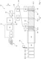
- FIG. 1 shows schematically a wood-based panel manufacturing device according to the invention, here in the form of an OSB manufacturing device 10, which has a chip manufacturing device, here in the form of a coarse chip manufacturing device 12, which first debarks wood 14 in a debarker 16 and then chips it in a chipper 18 to form chips, here in the form of coarse chips 20.
- the chips 20 are dried in a dryer 22, preferably until they are kiln-dry.
- top chips 26 are separated from middle layer chips 28.
- the middle layer chips are smaller, in particular shorter, than the top chips 26.
- a bin 30 for example a rotating gluing drum or a mixer, in particular a trough mixer, which in the present case has a top layer chip gluing unit 30a and a middle layer chip gluing unit 30b, which glue the top chips 26 and the middle layer chips 28 respectively.
- Cover chips 26, which can also be referred to as cover layer chips, are scattered by a first distribution device 32.1 to form a first cover layer 34.1.
- a first flame retardant liquid application device 36.1 is used to apply a schematically drawn flame retardant liquid 38 to the first cover layer 34.
- Cover chips 26 are also scattered by a second distribution device 32.2 to form a second cover layer 34.2.
- a schematically drawn flame retardant liquid 38 is applied to the first cover layer 34 by means of a second flame retardant liquid application device 36.2.
- a schematically drawn flame retardant liquid 38 is applied to the second cover layer 34.2.
- Middle layer chips 38 are spread onto the first cover layer 4 30.1 by means of a third distribution device 32.3, so that they form a middle layer 40. It is possible, but not necessary and in the Figure 1 In the embodiment shown, it is not provided that flame retardant 38 is applied to the middle layer by means of a flame retardant liquid application device.
- the first cover layer 34.1, the middle layer 40 and the second cover layer 34.2 together form a chip layer 42, which is pressed into an OSB 46 by means of a hot press 44.
- FIG 2 shows a schematic view of the OSB manufacturing device 10 in a side view.
- the flame retardant liquid application devices 36.1, 36.2 have together or - as in Figure 1 shown - a reservoir 50.1, 50.2 in which the flame retardant liquid 38 is contained.
- a heater 52.1, 52.2 the flame retardant liquid 38 can be brought to a predetermined temperature T 28 , for which, for example, 50°C ⁇ T 28 ⁇ 95°C applies.
- the OSB production device 10 can have a pressure difference generator 58, which is designed to apply a pressure difference to the first cover layer 34.1. This creates coarse chips 20 containing flame retardant.
- a pressure p j of, for example, 100 hPa ⁇ p j ⁇ 800 hPa is therefore present at the suction chambers 62.j. It is possible that the pressures in the individual suction chambers 62.j differ from one another. Valves not shown can be used for this purpose.
- the suction chambers 62.j are located on a conveyor belt 64, in particular a metal belt, of a belt conveyor 66, which has openings, for example holes. As a result, the pressure p j is applied to the first cover layer 34.1.
- a first inspection system 70.1 can be arranged behind the pressure difference generator 58 in the material flow direction M, which has a camera 72.1.
- the camera 72 detects light that is reflected, emitted and/or not absorbed by a dye in the flame retardant liquid 38.
- the camera 72.1 detects fluorescent light.
- an actual flame retardant distribution k ist (x,y) is determined, which indicates a concentration k of flame retardant depending on the area coordinates x, y.
- the camera 72.1 can be used as a moisture meter and measure the moisture distribution in the covering layer 34.1 using reflected or absorbed IR light.
- a control 74 compares the actual flame retardant distribution k ist (x,y) with a target flame retardant distribution k soll (x,y) and controls the nozzles 56.k individually so that a deviation between the actual flame retardant distribution k ist (x,y) and the target flame retardant distribution k soll (x,y) is minimized.
- the inspection system prefferably has a UV light source 76.1 that illuminates the cover layer 22 in a field of view G of the camera 72.1.
- the field of view G is the area of the cover layer 34.1 that is recorded by the camera 72.
- Figure 1 shows that - regardless of other features of this embodiment - a cutting device 78 can be arranged behind the hot press 44 in the material flow direction, which cuts the OSB board 46 into individual board segments 80.I.
- a second inspection system 82 see Figure 3
- camera 84 records a cut surface 86 of the respective plate segment 80.I.
- a second actual flame retardant distribution k ist,2 (y,z) is determined, which also encodes the depth dependence of the concentration k of flame retardant.
- the second actual flame retardant distribution k ist,2 (y,z) encodes a depth profile of the dye.
- the control 74 is designed to change the pressures p j in the at least one suction chamber 60.j and/or a conveyor belt speed v 62 of the conveyor belt 62, so that the second actual flame retardant distribution k ist,2 (y,z) approaches a second target flame retardant distribution k soll,2 (y,z).
Landscapes
- Life Sciences & Earth Sciences (AREA)
- Engineering & Computer Science (AREA)
- Manufacturing & Machinery (AREA)
- Wood Science & Technology (AREA)
- Forests & Forestry (AREA)
- Dry Formation Of Fiberboard And The Like (AREA)
Abstract
Die Erfindung betrifft ein Verfahren zum Herstellen von OSB mit den Schritten: Herstellen von Grobspänen, Beleimen der Grobspäne, sodass beleimte Grobspäne entstehen, Anordnen der beleimten Grobspäne auf einem Transportband, sodass eine Spanschicht entsteht, Aufbringen einer Flammschutzmittelflüssigkeit auf die Spanschicht und Verpressen der Spanschicht, sodass die OSB entsteht.The invention relates to a method for producing OSB with the steps: producing coarse chips, applying glue to the coarse chips so that glued coarse chips are produced, arranging the glued coarse chips on a conveyor belt so that a chip layer is produced, applying a flame retardant liquid to the chip layer and pressing the chip layer so that the OSB is produced.
Description
Die Erfindung betrifft ein Verfahren zum Herstellen von, insbesondere schwerentflammbaren, OSB (OSB, englisch für oriented strand board), die auch als Grobspanplatten bezeichnet werden können.The invention relates to a method for producing, in particular, flame-retardant OSB (oriented strand board), which can also be referred to as chipboard.
Gemäß einem zweiten Aspekt betrifft die Erfindung eine OSB-Herstellvorrichtung mit (a) einer Grobspan-Herstellvorrichtung zum Herstellen von Grobspänen aus Holz, (b) einem Trockner zum Trocknen der Grobspäne, der mit der Grobspan-Herstellvorrichtung verbunden ist, (c) einem Bandförderer, der in Materialflussrichtung hinter dem Trockner angeordnet ist, (d) einer ersten Verteilvorrichtung zum Verteilen von Grobspänen auf dem Bandförderer, sodass eine erste Deckschicht entsteht, (e) einer zweiten Verteilvorrichtung zum Verteilen von Grobspänen, sodass eine zweite Deckschicht oberhalb der ersten Deckschicht entsteht, sodass eine Spanschicht entsteht, und (d) einer Presse zum Verpressen der Spanschicht zu einer OSB-Platte. Die OSB-Herstellvorrichtung kann auch als Grobspanplatten-Herstellvorrichtung bezeichnet werden.According to a second aspect, the invention relates to an OSB manufacturing device with (a) a coarse chip manufacturing device for producing coarse chips from wood, (b) a dryer for drying the coarse chips, which is connected to the coarse chip manufacturing device, (c) a belt conveyor arranged behind the dryer in the material flow direction, (d) a first distribution device for distributing coarse chips on the belt conveyor so that a first cover layer is formed, (e) a second distribution device for distributing coarse chips so that a second cover layer is formed above the first cover layer so that a chip layer is formed, and (d) a press for pressing the chip layer into an OSB board. The OSB manufacturing device can also be referred to as a coarse chipboard manufacturing device.
Es ist günstig, bei der Herstellung von schwerentflammbaren OSB möglichst wenig Flammschutzmittel verwenden zu müssen, da dieses einen beträchtlichen Kostenaufwand bedeutet. Ein Grund dafür ist, dass Flammschutzmittel selbst teuer ist. Zudem führt Flammschutzmittel dazu, dass mehr Leim verwendet werden muss, um die gleiche mechanische Festigkeit zu erhalten, wie eine nicht schwerentflammbare OSB-Platte, was ebenfalls unerwünscht ist. Zudem sind die meisten Flammschutzmittel schlecht wasserlöslich, sodass durch das Einbringen des Flammschutzmittels in die Späne zudem große Mengen Wasser eingetragen werden, die oft im weiteren Verarbeitungsprozess entfernt werden müssen.It is beneficial to use as little flame retardant as possible when producing flame-retardant OSB, as this is very costly. One reason for this is that flame retardants themselves are expensive. In addition, flame retardants mean that more glue has to be used to achieve the same mechanical strength as a non-flame-retardant OSB board, which is also undesirable. In addition, most flame retardants are poorly soluble in water, so that introducing the flame retardant into the chips also introduces large amounts of water, which often have to be removed during further processing.
Der Erfindung liegt die Aufgabe zugrunde, die Herstellung von schwerentflammbaren Holzwerkstoffplatten, insbesondere OSB, zu verbessern.The invention is based on the object of improving the production of flame-retardant wood-based panels, in particular OSB.
Die Erfindung löst das Problem durch ein Verfahren zum Herstellen von OSB mit den Schritten (a) Herstellen von Grobspänen, (b) Beleimen der Grobspäne, sodass beleimte Grobspäne entstehen, (c) Anordnen der beleimten Grobspäne auf einem Transportband, sodass eine Spanschicht entsteht, (d) Aufbringen einer Flammschutzmittelflüssigkeit auf diese Spanschicht und (e) Verpressen der Spanschicht, sodass die OSB-Platte entsteht.The invention solves the problem by a method for producing OSB with the steps (a) producing coarse chips, (b) applying glue to the coarse chips so that glued coarse chips are formed, (c) arranging the glued coarse chips on a conveyor belt so that a chip layer is formed, (d) applying a flame retardant liquid to this chip layer and (e) pressing the chip layer so that the OSB board is formed.
In ihrer allgemeinsten Form löst die Erfindung das Problem Verfahren zum Herstellen von Holzwerkstoffplatten mit den Schritten (a) Herstellen von Spänen, (b) Beleimen der Späne, sodass beleimte Späne entstehen, (c) Anordnen der beleimten Späne auf einem Transportband, sodass eine Spanschicht entsteht, (d) Aufbringen einer Flammschutzmittelflüssigkeit auf diese Spanschicht und (e) Verpressen der Spanschicht, sodass die Holzwerkstoffplatte entsteht. Wenn im Folgenden von Grobspänen gesprochen wird, sind normale Späne, die keine Grobspäne sind, im Rahmen dieser allgemeinsten Form der Erfindung mit gemeint.In its most general form, the invention solves the problem of a method for producing wood-based panels with the steps (a) producing chips, (b) applying glue to the chips so that glued chips are produced, (c) arranging the glued chips on a conveyor belt so that a chip layer is produced, (d) applying a flame retardant liquid to this chip layer and (e) pressing the chip layer so that the wood-based panel is produced. When coarse chips are mentioned below, normal chips that are not coarse chips are also meant within the scope of this most general form of the invention.
Gemäß einem zweiten Aspekt löst die Erfindung das Problem durch eine gattungsgemäße OSB-Herstellvorrichtung, die (a) eine erste Flammschutzmittelflüssigkeits-Aufbringvorrichtung, die angeordnet ist zum Aufbringen einer Flammschutzmittelflüssigkeit auf die erste Deckschicht, und (b) eine zweite Flammschutzmittelflüssigkeits-Aufbringvorrichtung, die angeordnet ist zum Aufbringen einer Flammschutzmittelflüssigkeit auf die zweite Deckschicht aufweist.According to a second aspect, the invention solves the problem by a generic OSB manufacturing device which has (a) a first flame retardant liquid application device which is arranged to apply a flame retardant liquid to the first cover layer, and (b) a second flame retardant liquid application device which is arranged to apply a flame retardant liquid to the second cover layer.
In Ihrer allgemeinsten Form löst die Erfindung das Problem durch eine Holzwerkstoffplatten-Herstellvorrichtung mit (a) einer Span-Herstellvorrichtung zum Herstellen von Spänen aus Holz, (b) einem Trockner zum Trocknen der Späne, der mit der Grobspan-Herstellvorrichtung verbunden ist, (c) einem Bandförderer, der in Materialflussrichtung hinter dem Trockner angeordnet ist, (d) einer ersten Verteilvorrichtung zum Verteilen von Spänen auf dem Bandförderer, sodass eine erste Deckschicht entsteht, (e) einer zweiten Verteilvorrichtung zum Verteilen von Spänen, sodass eine zweite Deckschicht oberhalb der ersten Deckschicht entsteht, sodass eine Spanschicht entsteht (d) einer Presse zum Verpressen der Spanschicht zu einer OSB-Platte, (e) eine erste Flammschutzmittelflüssigkeits-Aufbringvorrichtung, die angeordnet ist zum Aufbringen einer Flammschutzmittelflüssigkeit auf die erste Deckschicht, und (d) eine zweite Flammschutzmittelflüssigkeits-Aufbringvorrichtung, die angeordnet ist zum Aufbringen einer Flammschutzmittelflüssigkeit auf die zweite Deckschicht. Wenn im Folgenden von OSB gesprochen wird, sind Holzwerkstoffplatten allgemein im Rahmen dieser allgemeinsten Form der Erfindung mit gemeint, wird von einer Grobspan-Herstellvorrichtung gesprochen, ist allgemein eine Span-Herstellvorrichtung mit gemeint.In its most general form, the invention solves the problem by a wood-based panel manufacturing device with (a) a chip manufacturing device for producing chips from wood, (b) a dryer for drying the chips, which is connected to the coarse chip manufacturing device, (c) a belt conveyor arranged behind the dryer in the material flow direction, (d) a first distribution device for distributing chips on the belt conveyor so that a first cover layer is formed, (e) a second distribution device for distributing chips so that a second cover layer is formed above the first cover layer so that a chip layer is formed (d) a press for pressing the chip layer into an OSB board, (e) a first flame retardant liquid application device arranged to apply a flame retardant liquid to the first cover layer, and (d) a second flame retardant liquid application device, which is arranged to apply a flame retardant liquid to the second cover layer. When OSB is mentioned below, wood-based panels are generally meant within the scope of this most general form of the invention; when a coarse chip production device is mentioned, a chip production device is generally meant.
Die erste Flammschutzmittelflüssigkeits-Aufbringvorrichtung ist vorzugsweise in Materialflussrichtung vor der zweiten Flammschutzmittelflüssigkeits-Aufbringvorrichtung und/oder vor der zweiten Verteilvorrichtung angeordnet.The first flame retardant liquid application device is preferably arranged in the material flow direction upstream of the second flame retardant liquid application device and/or upstream of the second distribution device.
Vorteilhaft an der Erfindung ist, dass - im Vergleich zu einem Einsprühen der Flammschutzmittelflüssigkeit in einen Mischer - in der Regel geringere Sprühverluste auftreten. Zudem kommt es in der Regel zu keinem Verlust an Flammschutzmittel durch aneinander oder an Komponenten der OSB-Herstellvorrichtung reibenden Späne.The advantage of the invention is that - compared to spraying the flame retardant liquid into a mixer - there are generally fewer spray losses. In addition, there is generally no loss of flame retardant due to chips rubbing against each other or against components of the OSB production device.
Günstig ist zudem, dass zwischen dem Ort des Aufbringens der Flammschutzmittelflüssigkeit und einer Presse zum Verpressen der Spanschicht nur ein geringer Abstand bestehen muss. Gemäß einer bevorzugten Ausführungsform ist dieser Abstand kleiner als 30 m. Dadurch vermindert sich, insbesondere beim Anfahren oder beim Wechsel auf die Herstellung von schwerentflammbaren OSB, der Ausschuss an OSB, deren Gehalt an Flammschutzmittel hinreichend hoch ist. Auf diese Weise kann auch die Produktion von schwerentflammbaren OSB und nicht OSB mit der gleichen OSB-Herstellvorrichtung hergestellt werden. Weiterhin wird die Reaktionszeit zwischen Leim und Flammschutzmittel bzw. dem Wasser im Flammschutzmittel verkürzt.It is also advantageous that there only needs to be a small distance between the place where the flame retardant liquid is applied and a press for pressing the chip layer. According to a preferred embodiment, this distance is less than 30 m. This reduces the amount of OSB that has a sufficiently high flame retardant content, particularly when starting up or changing to the production of flame-retardant OSB. In this way, flame-retardant OSB and non-OSB can also be produced using the same OSB production device. Furthermore, the reaction time between glue and flame retardant or the water in the flame retardant is shortened.
Im Rahmen der vorliegenden Beschreibung werden unter Grobspänen insbesondere Holzspäne verstanden, die im Größenintervall 200±30 cm x 20±4 cm x 0,5±0,2 cm liegen.In the context of the present description, coarse chips are understood to mean in particular wood chips which are in the size range 200±30 cm x 20±4 cm x 0.5±0.2 cm.
Insbesondere handelt es sich bei dem erfindungsgemäßen Verfahren um ein Verfahren zum Herstellen von schwerentflammbaren OSB nach DIN EN 13823 (single burner item) oder schwerentflammbaren OSB nach DIN EN 13501-1.In particular, the method according to the invention is a method for producing flame-retardant OSB according to DIN EN 13823 (single burner item) or flame-retardant OSB according to DIN EN 13501-1.
Bei der Flammschutzmittelflüssigkeit handelt es sich vorzugsweise um eine wässrige Lösung. Die Flammschutzmittelflüssigkeit enthält vorzugsweise zumindest eine organische oder anorganische phosphorhaltige und/oder stickstoffhaltige Verbindung. Vorzugsweise ist das Flammschutzmittel borfrei.The flame retardant liquid is preferably an aqueous solution. The flame retardant liquid preferably contains at least one organic or inorganic phosphorus-containing and/or nitrogen-containing compound. The flame retardant is preferably boron-free.
Unter Verpressen der Spanschicht wird insbesondere verstanden, dass zumindest die Grobspäne verpresst werden. Insbesondere ist es möglich, dass zudem weitere Späne, die keine Grobspäne sind, mit den Grobspänen verpresst werden. Zudem ist es möglich und stellt eine bevorzugte Ausführungsform dar, dass aus den Grobspänen eine erste Deckschicht und eine zweite Deckschicht gestreut werden und mit einer Mittelschicht, die zwischen den beiden Deckschichten angeordnet ist, zur OSBverpresst werden.Pressing the chip layer is understood in particular to mean that at least the coarse chips are pressed. In particular, it is possible that additional chips that are not coarse chips are pressed with the coarse chips. It is also possible and represents a preferred embodiment that a first cover layer and a second cover layer are scattered from the coarse chips and pressed with a middle layer that is arranged between the two cover layers to form the OSB.
Unter dem Verpressen wird insbesondere ein Verpressen mittels einer Bandpresse verstanden. In anderen Worten ist die Presse vorzugsweise eine Bandpresse.Pressing is understood to mean pressing using a belt press. In other words, the press is preferably a belt press.
Unter der Flammschutzmittelflüssigkeit wird insbesondere eine Lösung, Emulsion oder Dispersion verstanden, die Flammschutzmittel in einer Flüssigphase, insbesondere einem Lösungsmittel, enthält.The flame retardant liquid is understood to mean in particular a solution, emulsion or dispersion which contains flame retardants in a liquid phase, in particular a solvent.
Unter dem Aufbringen der Flammschutzmittelflüssigkeit auf die Grobspäne wird insbesondere ein Aufsprühen, Aufgiessen oder Aufdüsen verstanden.The application of the flame retardant liquid to the coarse chips is understood in particular to mean spraying, pouring or jetting.
Unter dem Verteilen von Grobspänen auf dem Bandförderer wird insbesondere ein Verteilen der Grobspäne auf einem Transportband des Bandförderers verstanden.The distribution of coarse chips on the belt conveyor is understood in particular to mean the distribution of the coarse chips on a conveyor belt of the belt conveyor.
Unter dem Merkmal, dass die zweite Flammschutzmittelflüssigkeits-Aufbringvorrichtung angeordnet ist zum Aufbringen einer Flammschutzmittelflüssigkeit auf die zweite Deckschicht, wird insbesondere verstanden, dass das Flammschutzmittel so aufgebracht wird, dass es die zweite Deckschicht benetzt, vorzugsweise nicht aber die erste Deckschicht oder eine etwaige vorhandene Mittelschicht. Insbesondere bedeutet das Aufbringen auf die Deckschicht nicht nur ein Aufbringen oberhalb der Deckschicht.The feature that the second flame retardant liquid application device is arranged to apply a flame retardant liquid to the second cover layer is understood in particular to mean that the flame retardant is applied in such a way that it wets the second cover layer, but preferably not the first cover layer or any middle layer that may be present. In particular, application to the cover layer does not just mean application above the cover layer.
Unter einem Transportband wird insbesondere ein flexibles Bauteil zum endlosen Fördern verstanden. Es ist möglich, nicht aber notwendig, dass das Transportband aus Metall, einer Maschenstruktur, einem Textil oder einem entropieelastischen Material, beispielsweise Gummi, aufweist.A conveyor belt is understood to be a flexible component for endless conveying. It is possible, but not necessary, for the conveyor belt to be made of metal, a mesh structure, a textile or an entropy-elastic material, such as rubber.
Der Begriff wird als Oberbegriff zu Deckschicht, Mittelschicht und Spanschicht verwendet.The term is used as a generic term for top layer, middle layer and chip layer.
Unter einer Spanschicht wird eine Schicht aus Spänen verstanden. Das kann die Deckschicht, die Mittelschicht oder die Spanschicht sein, aber auch zwei oder drei dieser Schichten oder gegebenenfalls weiteren Schichten aus Spänen.A chip layer is a layer made of chips. This can be the top layer, the middle layer or the chip layer, but also two or three of these layers or possibly further layers made of chips.
Gemäß einer bevorzugten Ausführungsform umfasst das Verfahren den Schritt des Trocknens der Grobspäne vor dem Beleimen. Dadurch, dass die Grobspäne erst beleimt werden und dann das Flammschutzmittel aufgebracht wird, werden die Verluste an Flammschutzmittel, insbesondere durch Abreiben, vermindert.According to a preferred embodiment, the method comprises the step of drying the coarse chips before applying the glue. By first applying the glue to the coarse chips and then applying the flame retardant, the losses of flame retardant, in particular through abrasion, are reduced.
Gemäß einer bevorzugten Ausführungsform umfasst das Verfahren die Schritte (a) Herstellen von Deckspänen, insbesondere in Form von Grobspänen, und Mittelschichtspänen, (b) optional Trocknen, insbesondere gemeinsames Trocknen, der Grobspäne und Mittelschichtspäne, (c) optional Trennen von Grobspänen und Mittelschichtspänen, insbesondere getrockneten Grobspänen und Mittelschichtspänen (d) Herstellen einer ersten Deckschicht aus Grobspänen, (e) Aufbringen der Flammschutzmittelflüssigkeit auf die Deckschicht (f) Herstellen einer Mittelschicht oberhalb der Deckschicht aus Mittelschichtspänen, (g) Herstellen einer zweiten Deckschicht aus Deckspänen oberhalb der Mittelschicht, sodass die Spanschicht entsteht und (h) Aufbringen der Flammschutzmittelflüssigkeit auf die zweite Deckschicht. Vorzugsweise werden danach die erste Deckschicht, die zweite Deckschicht und Mittelschicht, die eine Spanschicht bilden zur OSB verpresst.According to a preferred embodiment, the method comprises the steps (a) producing top chips, in particular in the form of coarse chips, and middle layer chips, (b) optionally drying, in particular drying together, the coarse chips and middle layer chips, (c) optionally separating coarse chips and middle layer chips, in particular dried coarse chips and middle layer chips (d) producing a first top layer from coarse chips, (e) applying the flame retardant liquid to the top layer (f) producing a middle layer above the top layer from middle layer chips, (g) producing a second top layer from top chips above the middle layer so that the chip layer is created and (h) applying the flame retardant liquid to the second top layer. Preferably, the first top layer, the second top layer and the middle layer, which form a chip layer, are then pressed to form OSB.
Es ist möglich, nicht aber notwendig, dass die Mittelschichtspäne ebenfalls Grobspäne sind. Insbesondere ist es möglich, dass die Mittelschichtspäne eine Längenverteilungsdichte haben, wobei die Längenverteilungsdichte die Anzahl an Grobspänen mit einer bestimmten Länge angibt. Die Längenverteilungsdichte hat vorzugsweise einen Mittelschichtspanlängen-Median, der kleiner ist als ein Deckschichtspanlängen-Median der Längenverteilungsdichte der Deckspäne. In anderen Worten sind die Späne, die die Deckschichten bilden, länger als die Späne, die die Mittelschicht bilden.It is possible, but not necessary, that the middle layer chips are also coarse chips. In particular, it is possible that the middle layer chips have a length distribution density, whereby the length distribution density indicates the number of coarse chips with a certain length. The length distribution density preferably has a middle layer chip length median that is smaller than a top layer chip length median of the length distribution density of the top chips. In other words, the chips that form the top layers are longer than the chips that form the middle layer.
Es ist möglich, nicht aber notwendig, dass auch auf die Mittelschicht Flammschutzmittelflüssigkeit aufgebracht wird. Insbesondere wird auf die Mittelschicht keine Flammschutzmittelflüssigkeit aufgebracht. In diesem Fall konzentriert sich das Flammschutzmittel in den Deckschichten, wodurch eine besonders hohe Schwerentflammbarkeit bei gleichzeitig geringem Gehalt der OSB an Flammschutzmittel erreicht.It is possible, but not necessary, that flame retardant liquid is also applied to the middle layer. In particular, no flame retardant liquid is applied to the middle layer. In this case, the flame retardant is concentrated in the outer layers, which results in particularly high flame retardancy while at the same time the OSB has a low flame retardant content.
Vorzugsweise umfasst das Verfahren die Schritte (a) Erfassen eines Feuchtigkeitsgehalts der OSB und/oder der Spanschicht nach dem Aufbringen des Flammschutzmittels und (b) verändern einer Aufbringmenge an Flammschutzmittelflüssigkeit und/oder einer Flammschutzmittel-Konzentration an Flammschutzmittel in der Flammschutzmittelflüssigkeit , sodass der Spanschicht-Feuchtigkeitsgehalt in einem vorgegebenen Soll-Feuchtigkeitsgehaltintervall liegt und ein Flammschutzmittelgehalt der Spanschicht und/oder der OSB in einem vorgegebenen Soll-Flammschutzmittelgehaltintervall liegt.Preferably, the method comprises the steps of (a) detecting a moisture content of the OSB and/or the chip layer after application of the flame retardant and (b) changing an application amount of flame retardant liquid and/or a flame retardant concentration of flame retardant in the flame retardant liquid so that the chip layer moisture content is within a predetermined target moisture content interval and a flame retardant content of the chip layer and/or the OSB is within a predetermined target flame retardant content interval.
Insbesondere umfasst das Verfahren vorzugsweise die Schritte (a) Erfassen eines Deckschicht-Feuchtigkeitsgehalt der ersten Deckschicht und/oder der zweiten Deckschicht nach dem Aufbringen des Flammschutzmittels und (b) Verändern der Aufbringmenge an Flammschutzmittelflüssigkeit und/oder der Flammschutzmittel-Konzentration des Flammschutzmittels in der Flammschutzmittelflüssigkeit , sodass der Deckschicht-Feuchtigkeitsgehalt in einem vorgegebenen Soll-Deckschicht-Feuchtigkeitsgehaltintervall liegt.In particular, the method preferably comprises the steps of (a) detecting a top layer moisture content of the first top layer and/or the second top layer after application of the flame retardant and (b) changing the application amount of flame retardant liquid and/or the flame retardant concentration of the flame retardant in the flame retardant liquid so that the top layer moisture content lies in a predetermined target top layer moisture content interval.
Das Vermindern der Flammschutzmittel-Konzentration erfolgt beispielsweise durch Zugeben von Lösungsmittel, insbesondere Wasser, zur Flammschutzmittelflüssigkeit. Ein Erhöhen der Flammschutzmittel-Konzentration erfolgt beispielsweise durch Vermindern des Zugebens von Lösungsmittel. Alternativ kann das Erhöhen der Flammschutzmittel-Konzentration ein Erhöhen der Temperatur der Flammschutzmittelflüssigkeit umfassen, wenn - wie gemäß einer bevorzugten Ausführungsform vorgesehen - das Flammschutzmittel mit seiner Sättigungskonzentration in der Flammschutzmittelflüssigkeit vorliegt. Beispielsweise wird das Lösungsmittel durch ein Bad an festem Flammschutzmittel geleitet. Je höher die Temperatur des Lösungsmittels, desto höher die Flammschutzmittel-Konzentration.The reduction of the flame retardant concentration is carried out, for example, by adding solvent, in particular water, to the flame retardant liquid. The increase of the flame retardant concentration is carried out, for example, by reducing the addition of solvent. Alternatively, the increase of the flame retardant concentration can comprise increasing the temperature of the flame retardant liquid if - as according to a preferred embodiment intended - the flame retardant is present at its saturation concentration in the flame retardant liquid. For example, the solvent is passed through a bath of solid flame retardant. The higher the temperature of the solvent, the higher the flame retardant concentration.
Die Spanschicht hat eine Spanschicht-Temperatur, die Deckschicht eine Deckschicht-Temperatur und die Mittelschicht eine Mittelschicht-Temperatur. Diese Temperaturen beziehen sich auf eine Position in Materialflussrichtung unmittelbar vor der Stelle, an der die Flammschutzmittelflüssigkeit aufgebracht wird. Es handelt sich jeweils um die Durchschnittstemperatur über die volle Breite der jeweiligen Schicht.The chip layer has a chip layer temperature, the top layer has a top layer temperature and the middle layer has a middle layer temperature. These temperatures refer to a position in the direction of material flow immediately before the point where the flame retardant liquid is applied. In each case, they are the average temperature over the full width of the respective layer.
Vorzugsweise sind die Temperatur der Flammschutzmittelflüssigkeit und die Flammschutzmittel-Konzentration so gewählt, dass eine Abkühlung der Flammschutzmittelflüssigkeit auf die jeweilige Temperatur (Spanschicht-Temperatur, Deckschicht-Temperatur oder Mittelschicht-Temperatur) dazu führt, dass bei dieser Temperatur der Gehalt an Flammschutzmittel unterhalb der Löslichkeit des Flammschutzmittels liegt. Auf diese Weise wird wenig Lösungsmittel in die entsprechende Schicht eingebracht.Preferably, the temperature of the flame retardant liquid and the flame retardant concentration are selected such that cooling the flame retardant liquid to the respective temperature (chip layer temperature, top layer temperature or middle layer temperature) results in the flame retardant content at this temperature being below the solubility of the flame retardant. In this way, little solvent is introduced into the corresponding layer.
Vorzugsweise hat die Flammschutzmittelflüssigkeit beim Aufbringen auf die jeweilige Schicht eine Temperatur von zumindest 50°C, insbesondere zumindest 60°C, vorzugsweise 70°C, besonders bevorzugt zumindest 80°C. Eine hohe Temperatur erhöht in der Regel die Löslichkeit des Flammschutzmittels in dem Lösungsmittel, sodass weniger Lösungsmittel, in der Regel Wasser, notwendig ist, um eine vorgegebene Menge an Flammschutzmittel zu lösen. Zudem sinkt die Viskosität von Wasser mit zunehmender Temperatur, sodass die Flammschutzmittelflüssigkeit leichter in die Grobspäne eindringen kann.When applied to the respective layer, the flame retardant liquid preferably has a temperature of at least 50°C, in particular at least 60°C, preferably 70°C, particularly preferably at least 80°C. A high temperature generally increases the solubility of the flame retardant in the solvent, so that less solvent, usually water, is required to dissolve a given amount of flame retardant. In addition, the viscosity of water decreases with increasing temperature, so that the flame retardant liquid can penetrate the coarse chips more easily.
Günstig ist es, wenn die Flammschutzmittelflüssigkeit eine Konzentration an Flammschutzmittel enthält, die zumindest 60 %, insbesondere zumindest 70 %, vorzugsweise zumindest 80 %, besonders bevorzugt zumindest 90 %, der maximalen Löslichkeit des Flammschutzmittels bei der entsprechenden Temperatur entspricht. Ein weiterer Vorteil ist, dass durch das erwärmte Flammschutzmittel die beiden Deckschichten eine Temperaturerhöhung erfahren, welche eine höhere Pressengeschwindigkeit ermöglicht.It is advantageous if the flame retardant liquid contains a concentration of flame retardant that corresponds to at least 60%, in particular at least 70%, preferably at least 80%, particularly preferably at least 90%, of the maximum solubility of the flame retardant at the corresponding temperature. A further advantage is that the heated flame retardant causes the two cover layers to experience a temperature increase, which enables a higher press speed.
Günstig ist es, wenn die Flammschutzmittelflüssigkeit einen Viskositätssenker, insbesondere ein Tensid, enthält. Dadurch dringen die Flammschutzmittelflüssigkeit und damit das Flammschutzmittel schneller in die Späne ein. Vorzugsweise enthält die Flammschutzmittelflüssigkeit einen Viskositätssenker.It is advantageous if the flame retardant liquid contains a viscosity reducer, in particular a surfactant. This allows the flame retardant liquid and thus the flame retardant to penetrate the chips more quickly. The flame retardant liquid preferably contains a viscosity reducer.
Günstig ist es, wenn das Verfahren den Schritt eines Anliegens einer Druckdifferenz an die mit Flammschutzmittelflüssigkeit benetzte oder benetzt werdende Spanschicht, Deckschicht oder Mittelschicht umfasst. Das Anlegen der Druckdifferenz kann ein Anlegen eines Unterdrucks, insbesondere an eine Unterseite des Bandförderers auf eine Oberseite der Spanschicht, Deckschicht oder Mittelschicht umfassen.It is advantageous if the method comprises the step of applying a pressure difference to the chip layer, cover layer or middle layer that is or will be wetted with flame retardant liquid. The application of the pressure difference can comprise applying a negative pressure, in particular to an underside of the belt conveyor on an upper side of the chip layer, cover layer or middle layer.
Vorteilhaft daran ist, dass der Verbrauch an Flammschutzmittel in der Regel im Vergleich zu herkömmlich hergestellten OSB verringerbar ist. Dadurch, dass eine Druckdifferenz an die Grobspäne angelegt wird, wird die Flammschutzmittelflüssigkeit zumindest teilweise in die Grobspäne eingesogen. Dadurch kommt es weniger zur Bildung einer Kruste aus Flammschutzmitteln auf den Grobspänen. Wenn das Flammschutzmittel zumindest teilweise in die Grobspäne eindringt, erhöht sich dessen Wirkung.The advantage of this is that the consumption of flame retardants can generally be reduced compared to conventionally produced OSB. By applying a pressure difference to the coarse chips, the flame retardant liquid is at least partially absorbed into the coarse chips. This means that there is less of a crust of flame retardants forming on the coarse chips. If the flame retardant at least partially penetrates the coarse chips, its effectiveness is increased.
Durch das Einsaugen und/oder Einpressen der Flammschutzmittelflüssigkeit in die Grobspäne kommt es zudem oft zu weniger chemischen Reaktionen mit dem Leim. In der Regel muss daher die Leimmenge deutlich weniger gesteigert werden, um einen Festigkeitsverlust durch das Hinzufügen des Flammschutzmittels auszugleichen.By sucking and/or pressing the flame retardant liquid into the coarse chips, there are often fewer chemical reactions with the glue. As a rule, the amount of glue therefore needs to be increased significantly less to compensate for a loss of strength caused by the addition of the flame retardant.
Unter dem Anlegen der Druckdifferenz durch Anlegen von Überdruck wird insbesondere verstanden, dass eine Druckdifferenz zwischen einer ersten Seitenfläche der Grobspäne und der gegenüberliegenden Seitenfläche der Grobspäne erzeugt wird. Die beiden Seitenflächen sind um die Höhe des Grobspans voneinander entfernt, die vorzugsweise 0,5 ± 0,2 cm beträgt.The creation of the pressure difference by applying excess pressure is understood in particular to mean that a pressure difference is generated between a first side surface of the coarse chips and the opposite side surface of the coarse chips. The two side surfaces are spaced apart by the height of the coarse chips, which is preferably 0.5 ± 0.2 cm.
Unter dem Anlegen der Druckdifferenz durch Anlegen von Unterdruck wird insbesondere verstanden, dass an die Grobspäne, insbesondere an die Deckschicht, ein Druck angelegt wird, der um zumindest 200 hPa, vorzugsweise zumindest 400 hPa, besonders bevorzugt zumindest 600 hPa, kleiner ist als der Umgebungsdruck.The application of the pressure difference by applying negative pressure is understood in particular to mean that a pressure is applied to the coarse chips, in particular to the covering layer, which is at least 200 hPa, preferably at least 400 hPa, particularly preferably at least 600 hPa, lower than the ambient pressure.
Ein Beleimen erfolgt vorzugsweise ohne an den Grobspänen anliegende Druckdifferenz.Gluing is preferably carried out without a pressure difference applied to the coarse chips.
Vorzugsweise wird der Unterdruck an eine Unterseite eines Transportbands des Bandförderers angelegt. Das Transportband ist dazu gasdurchlässig. Beispielsweise ist das Transportband perforiert oder aus einem gasdurchlässigen Material aufgebaut, beispielsweise einem Textil. Alternativ kann das Transportband ein Metallband sein. Dieses Metallband ist vorzugsweise perforiert.Preferably, the negative pressure is applied to the underside of a conveyor belt of the belt conveyor. The conveyor belt is gas-permeable for this purpose. For example, the conveyor belt is perforated or made of a gas-permeable material, such as a textile. Alternatively, the conveyor belt can be a metal belt. This metal belt is preferably perforated.
Das Anlegen des Überdrucks erfolgt beispielsweise dadurch, dass die Schicht zunächst eine Walze passiert, die als Abdichtung fungiert, und dann in einen Überdruckbereich eintritt, in dem der Überdruck anliegt. Die Schicht liegt auf einem gasdurchlässigen Förderband, auf dessen dem Überdruckbereich abgewandte Seite ein geringerer Druck, beispielsweise Umgebungsdruck oder Unterdruck, anliegt. Die Schicht verlässt den Überdruckbereich, indem sie eine Walze passiert, die als Dichtung wirkt.The overpressure is applied, for example, by the layer first passing a roller that acts as a seal and then entering an overpressure area in which the overpressure is present. The layer lies on a gas-permeable conveyor belt, on the side of which facing away from the overpressure area there is a lower pressure, for example ambient pressure or negative pressure. The layer leaves the overpressure area by passing a roller that acts as a seal.
Vorzugsweise werden die Grobspäne getrocknet, bis sie darrtrocken sind. In diesem Zustand wird besonders leicht und schnell Flammschutzmittelflüssigkeit von den getrockneten Grobspänen aufgenommen. Gemäß einer bevorzugten Ausführungsform werden die flammschutzmittelhaltigen Grobspäne nicht wesentlich getrocknet. Hierunter ist insbesondere zu verstehen, dass der Feuchtegehalt der jeweiligen Schicht (Deckschicht, Mittelschicht oder Spanschicht) sich nach dem Aufbringen der Flammschutzmittelflüssigkeit um höchstens fünf Prozentpunkte, insbesondere um höchstens zwei Prozentpunkte, ändert.Preferably, the coarse chips are dried until they are kiln-dry. In this state, flame retardant liquid is absorbed particularly easily and quickly by the dried coarse chips. According to a preferred embodiment, the coarse chips containing flame retardant are not dried significantly. This is to be understood in particular that the moisture content of the respective layer (top layer, middle layer or chip layer) changes by a maximum of five percentage points, in particular by a maximum of two percentage points, after the flame retardant liquid has been applied.
Vorzugsweise hat die Grobspanschicht eine Spanschichtdicke, die höchstens dem Vierfachen, vorzugsweise höchstens dem Dreifachen, bevorzugt höchstens dem Doppelten, einer Grobspanlagendicke einer einzelnen Grobspanlage entspricht. Die Grobspanlagendicke ist die minimal erreichbare Dicke einer Grobspanlage. Diese ist die mittlere Höhe einer Anordnung von Grobspänen auf einer ebenen, horizontal verlaufenden Testfläche von 1 m2, wobei für diese Anordnung gilt, dass auf höchstens 75 % der Testfläche Abschnitte von zwei oder mehr Grobspänen übereinanderliegen und wobei zumindest 90%, vorzugsweise zumindest 95%, insbesondere 100%, der Testfläche von Grobspänen bedeckt sind.Preferably, the coarse chip layer has a chip layer thickness that is at most four times, preferably at most three times, preferably at most twice, the thickness of a coarse chip layer of a single coarse chip layer. The coarse chip layer thickness is the minimum achievable thickness of a coarse chip layer. This is the average height of an arrangement of coarse chips on a flat, horizontal test surface of 1 m 2 , whereby for this arrangement, the following applies: on a maximum of 75% of the test area has sections of two or more coarse chips lying on top of each other and at least 90%, preferably at least 95%, in particular 100%, of the test area being covered by coarse chips.
Vorzugsweise weist die Flammschutzmittelflüssigkeit einen Farbstoff auf. Dieser Farbstoff ist vorzugsweise im sichtbaren Bereich farblos. In diesem Fall kann der Farbstoff auch als Marker bezeichnet werden. Günstig ist es, wenn der Farbstoff im UV-Bereich absorbiert und/oder fluoresziert. In diesem Fall kann durch Bestrahlen mit UV-Licht und/oder Aufnehmen eines Bildes der jeweiligen Schicht und/oder der OSB-Platte mit einer im UV-Bereich empfindlichen Kamera eine Flammschutzmittelverteilung der Flammschutzmittelflüssigkeit und/oder des Flammschutzmittels erfasst werden.The flame retardant liquid preferably contains a dye. This dye is preferably colorless in the visible range. In this case, the dye can also be referred to as a marker. It is advantageous if the dye absorbs and/or fluoresces in the UV range. In this case, a flame retardant distribution of the flame retardant liquid and/or the flame retardant can be recorded by irradiating with UV light and/or taking an image of the respective layer and/or the OSB board with a camera sensitive to the UV range.
Anhand der Flammschutzmittelverteilung wird gemäß einer bevorzugten Ausführungsform ein Prozessparameter in Form der Transportbandgeschwindigkeit des Transportbands und oder der Druckdifferenz und/oder einer flächenspezifischen Ausbringmenge an Flammschutzmittelflüssigkeit geregelt. In anderen Worten wird eine Abweichung zwischen einer Soll-Flammschutzmittelverteilung und der jeweils gemessenen Ist-Flammschutzmittelverteilung ermittelt und zumindest einer der genannten Parameter so geregelt werden, dass die Abweichung minimiert wird.According to a preferred embodiment, a process parameter in the form of the conveyor belt speed and/or the pressure difference and/or an area-specific application rate of flame retardant liquid is regulated based on the flame retardant distribution. In other words, a deviation between a target flame retardant distribution and the respective measured actual flame retardant distribution is determined and at least one of the parameters mentioned is regulated so that the deviation is minimized.
Eine erfindungsgemäße OSB-Herstellvorrichtung besitzt vorzugsweise eine dritte Verteilvorrichtung zum Verteilen von Spänen, sodass eine Mittelschicht oberhalb der ersten Deckschicht entsteht. Insbesondere ist die dritte Verteilvorrichtung so ausgebildet, dass die Mittelschicht auf der ersten Deckschicht zum Liegen kommt. Die zweite Verteilvorrichtung ist dann vorzugweise so ausgebildet, dass die zweite Deckschicht auf der Mittelschicht zum Liegen kommt. Entsprechend ist die zweite Verteilvorrichtung vorzugsweise in Materialflussrichtung hinter der dritten Verteilvorrichtung angeordnet.An OSB manufacturing device according to the invention preferably has a third distribution device for distributing chips so that a middle layer is created above the first cover layer. In particular, the third distribution device is designed so that the middle layer lies on the first cover layer. The second distribution device is then preferably designed so that the second cover layer lies on the middle layer. Accordingly, the second distribution device is preferably arranged behind the third distribution device in the direction of material flow.
Die OSB-Herstellvorrichtung besitzt vorzugsweise einen Beleimer, der in Materialflussrichtung hinter der Grobspan-Herstellvorrichtung und vorzugsweise hinter einem Trockner für die Grobspäne angeordnet ist. Der Beleimer ist vorzugsweise in Materialflussrichtung vor den Verteilvorrichtungen angeordnet. In anderen Worten verteilen die Verteilvorrichtungen beleimte Späne. Der Beleimer ist vorzugsweise eine rotierende Beleimtrommel oder ein Mischer, insbesondere ein Trogmischer.The OSB production device preferably has a hopper which is arranged in the material flow direction behind the coarse chip production device and preferably behind a dryer for the coarse chips. The hopper is preferably arranged in the material flow direction before the distribution devices. In other words The distribution devices distribute glued chips. The hopper is preferably a rotating gluing drum or a mixer, in particular a trough mixer.
Die OSB-Herstellvorrichtung besitzt vorzugsweise einen Klassierer zum Trennen von Deckspänen und Mittelschichtspänen. Der Klassierer ist vorzugsweise ein Sichter. Günstig ist es, wenn der Klassierer in Materialflussrichtung hinter der Grobspan-Herstellvorrichtung und/oder vor dem Beleimer angeordnet ist.The OSB production device preferably has a classifier for separating top layer chips and middle layer chips. The classifier is preferably a sifter. It is advantageous if the classifier is arranged behind the coarse chip production device and/or in front of the bucket in the direction of material flow.
Der Druckdifferenzerzeuger zum Anlegen der Druckdifferenz an die Spanschicht umfasst vorzugsweise einen Unterdruckerzeuger und/oder einen Überdruckerzeuger. Vorzugsweise besitzt der Differenzdruckerzeuger eine Unterdruckpumpe und zumindest eine Saugkammer, vorzugsweise zumindest zwei Saugkammern, insbesondere eine Mehrzahl an Saugkammern, die jeweils über ein Ventil mit der Unterdruckpumpe verbunden sind. Die Ventile sind vorzugsweise ausgebildet zum Vergrößern ihres Ventilöffnungsgrads bei abnehmendem Druck in der Saugkammer. In anderen Worten öffnen die Ventile umso weiter, je kleiner der Druck in der jeweiligen Saugkammer ist.The pressure difference generator for applying the pressure difference to the chip layer preferably comprises a vacuum generator and/or a pressure generator. The differential pressure generator preferably has a vacuum pump and at least one suction chamber, preferably at least two suction chambers, in particular a plurality of suction chambers, each of which is connected to the vacuum pump via a valve. The valves are preferably designed to increase their valve opening degree as the pressure in the suction chamber decreases. In other words, the valves open further the lower the pressure in the respective suction chamber.
Die Saugkammern sind insbesondere so angeordnet, dass zumindest 90 % der Fläche, vorzugsweise zumindest 95% der Fläche, besonders bevorzugt 100% der Fläche der Grobspanlage für zumindest eine vorgegebene Zeit von beispielsweise 1 Sekunde, insbesondere zumindest 5 Sekunden, mittels zumindest jeweils einer Saugkammer mit der Druckdifferenz, im vorliegenden Fall mit einem Unterdruck, beaufschlagbar ist.The suction chambers are arranged in particular in such a way that at least 90% of the surface, preferably at least 95% of the surface, particularly preferably 100% of the surface of the coarse chipping system can be subjected to the pressure difference, in the present case to a negative pressure, for at least a predetermined time of, for example, 1 second, in particular at least 5 seconds, by means of at least one suction chamber.
Vorzugsweise beträgt ein Unterdruck zumindest 300 hPa (und der Druck somit und 713 hPa), insbesondere zumindest 500 hPa (und der Druck somit und 513 hPa).Preferably, a negative pressure is at least 300 hPa (and the pressure is therefore 713 hPa), in particular at least 500 hPa (and the pressure is therefore 513 hPa).
Günstig ist es, wenn die OSB-Herstellvorrichtung ein Inspektionssystem zum Erfassen der Flammschutzmittelverteilung an Flammschutzmittel in der jeweiligen Schicht aufweist. Es kann sich hierbei um die Verteilung des Flammschutzmittels in der Fläche der Grobspanschicht handeln, also um die zweidimensionale Verteilung in Längsrichtung und Breitenrichtung der Grobspanschicht, nicht aber in Dickenrichtung.It is advantageous if the OSB manufacturing device has an inspection system for detecting the flame retardant distribution in the respective layer. This can be the distribution of the flame retardant in the surface of the coarse chip layer, i.e. the two-dimensional distribution in the length and width direction of the coarse chip layer, but not in the thickness direction.
Alternativ oder zusätzlich kann das Inspektionssystem ausgebildet sein zum Erfassen der Flammschutzmittelverteilung in der OSB. Es kann sich dann um die Verteilung des Flammschutzmittels in der Fläche der OSB handeln, also um die zweidimensionale Verteilung in Längsrichtung und Breitenrichtung der Grobspanschicht, und/oder der Verteilung des Flammschutzmittels in Dickenrichtung.Alternatively or additionally, the inspection system can be designed to detect the flame retardant distribution in the OSB. This can then be the distribution of the flame retardant in the surface of the OSB, i.e. the two-dimensional distribution in the longitudinal direction and width direction of the coarse chip layer, and/or the distribution of the flame retardant in the thickness direction.
Das Inspektionssystem besitzt vorzugsweise eine Kamera zum Erfassen von UV-Licht und/oder Fluoreszenzlicht, das beim Bestrahlen der Grobspanschicht bzw. der OSB mit UV-Licht entsteht. Vorzugsweise besitzt das Inspektionssystem zudem eine UV-Lichtquelle zum Bestrahlen der Grobspanschicht bzw. der OSB mit UV-Licht.The inspection system preferably has a camera for capturing UV light and/or fluorescent light that is generated when the coarse chip layer or the OSB is irradiated with UV light. The inspection system preferably also has a UV light source for irradiating the coarse chip layer or the OSB with UV light.
Bevorzugt umfasst die OSB-Herstellvorrichtung einen Feuchtigkeitsmesser zum Messen eines Spanschicht-Feuchtigkeitsgehalts einer Spanschicht, insbesondere der ersten Deckschicht und/oder der zweiten Deckschicht. Vorzugsweise ist der Feuchtigkeitmesser ausgebildet zum ortsaufgelösten Messen des Spanschicht-Feuchtigkeitsgehalts. Dieser Feuchtigkeitsmesser kann beispielsweise eine Infrarot-Lichtquelle und eine Infrarot-Kamera umfassen. Die Infrarot-Lichtquelle ist vorzugsweise ausgebildet zum Emittieren von Infrarotstrahlung mit einer Wellenlänge von 3±0,5 µm. In diesem Wellenbereich absorbiert Wasser dass Infrarotlicht besonders stark und reflektiert es entsprechend besonders wenig.The OSB production device preferably comprises a moisture meter for measuring a moisture content of a chip layer, in particular the first cover layer and/or the second cover layer. The moisture meter is preferably designed for spatially resolved measurement of the moisture content of the chip layer. This moisture meter can, for example, comprise an infrared light source and an infrared camera. The infrared light source is preferably designed to emit infrared radiation with a wavelength of 3±0.5 µm. In this wavelength range, water absorbs the infrared light particularly strongly and reflects it correspondingly very little.
Besonders bevorzugt besitzt die OSB-Herstellvorrichtung eine Regelung, die ausgebildet ist zum automatischen Ansteuern der ersten Flammschutzmittelflüssigkeit-Aufbringvorrichtung und/oder der zweiten Flammschutzmittelflüssigkeit-Aufbringvorrichtung zum Verändern einer Aufbringmenge an Flammschutzmittelflüssigkeit und/oder einer Konzentration des Flammschutzmittels, sodass der Spanschicht-Feuchtigkeitsgehalt in einem vorgegebenen Soll-Feuchtigkeitsgehaltintervall liegt und ein Flammschutzmittelgehalt der Spanschicht und/oder der OSB in einem vorgegebenen Soll- Flammschutzmittelgehaltintervall liegt.Particularly preferably, the OSB production device has a control system which is designed to automatically control the first flame retardant liquid application device and/or the second flame retardant liquid application device to change an application amount of flame retardant liquid and/or a concentration of the flame retardant, so that the chip layer moisture content is in a predetermined target moisture content interval and a flame retardant content of the chip layer and/or the OSB is in a predetermined target flame retardant content interval.
Günstig ist es, wenn zumindest eine der Flammschutzmittelflüssigkeits-Aufbringvorrichtungen zumindest zwei, insbesondere eine Mehrzahl, an Düsen aufweist, die individuell von der Regelung ansteuerbar sind. Die Regelung ist dann ausgebildet zum Ansteuern der Düsen der Flammschutzmittelflüssigkeits-Aufbringvorrichtung, sodass die räumliche Ist-Verteilung des Flammschutzmittels von einer vorgegebenen Soll-Verteilung, insbesondere einer räumlich konstanten Konzentration an Flammschutzmittel, möglichst wenig abweicht.It is advantageous if at least one of the flame retardant liquid application devices has at least two, in particular a plurality of, nozzles that can be individually controlled by the control system. The control system is then designed to control the nozzles of the flame retardant liquid application device so that the actual spatial distribution of the flame retardant is limited by a predetermined Target distribution, in particular a spatially constant concentration of flame retardant, deviates as little as possible.
Vorzugsweise umfasst die Flammschutzmittelflüssigkeits-Aufbringvorrichtung eine Temperaturregelung, die ausgebildet ist zum automatischen Einstellen einer SollTemperatur und/oder eine Konzentrationsregelung zum Einstellen einer Soll-Konzentration an Flammschutzmittel im Lösungsmittel. Bei dem Lösungsmittel handelt es sich vorzugsweise um Wasser. Durch die Temperatur lässt sich die Sättigungskonzentration des Flammschutzmittels im Wasser einstellen. Ist - wie gemäß einer bevorzugten Ausführungsform vorgesehen - die Flammschutzmittel-Aufbringvorrichtung eingerichtet zum Aufbringen einer Flammschutzmittelflüssigkeit , deren Konzentration an Flammschutzmittel der Sättigungsgrenze dazu entspricht, kann durch Erhöhen der Temperatur die Konzentration an Flammschutzmittel erhöht werden.The flame retardant liquid application device preferably comprises a temperature control which is designed to automatically set a target temperature and/or a concentration control for setting a target concentration of flame retardant in the solvent. The solvent is preferably water. The saturation concentration of the flame retardant in the water can be set by the temperature. If - as provided according to a preferred embodiment - the flame retardant application device is set up to apply a flame retardant liquid whose concentration of flame retardant corresponds to the saturation limit, the concentration of flame retardant can be increased by increasing the temperature.
Im Folgenden wird die Erfindung anhand der beigefügten Zeichnungen näher erläutert. Dabei zeigt
- Figur 1
- ein Flussdiagramm eines erfindungsgemäßen Verfahrens und
- Figur 2
- eine schematische Ansicht einer erfindungsgemäßen OSB-Herstellvorrichtung zum Durchführen eines erfindungsgemäßen Verfahrens.
- Figure 1
- a flow chart of a method according to the invention and
- Figure 2
- a schematic view of an OSB manufacturing device according to the invention for carrying out a method according to the invention.
In einem Klassierer 24, der im vorliegenden Fall als Sichter ausgebildet ist, werden Deckspäne 26 von Mittelschichtspänen 28 getrennt. Die Mittelschichtspäne sind kleiner, insbesondere kürzer, als die Deckspäne 26. In Materialflussrichtung M hinter dem Klassierer 24 ist ein Beleimer 30, beispielsweise eine rotierende Beleimtrommel oder ein Mischer, insbesondere ein Trogmischer, angeordnet, der im vorliegenden Fall eine Deckschichtspan-Beleimeinheit 30a und eine Mittelschichtspan-Beleimeinheit 30b aufweist, die jeweils die Deckspäne 26 bzw. die Mittelschichtspäne 28 beleimen.In a
Deckspäne 26, die auch als Deckschichtspäne bezeichnet werden können, werden von einer ersten Verteilvorrichtung 32.1 zu einer ersten Deckschicht 34.1 gestreut. Mittels einer ersten Flammschutzmittelflüssigkeits-Aufbringvorrichtung 36.1 wird eine schematisch eingezeichnete Flammschutzmittelflüssigkeit 38 auf die erste Deckschicht 34 aufgebracht.Cover chips 26, which can also be referred to as cover layer chips, are scattered by a first distribution device 32.1 to form a first cover layer 34.1. A first flame retardant liquid application device 36.1 is used to apply a schematically drawn
Deckspäne 26 werden zudem von einer zweiten Verteilvorrichtung 32.2 zu einer zweiten Deckschicht 34.2 gestreut. Mittels einer zweiten Flammschutzmittelflüssigkeits-Aufbringvorrichtung 36.2 wird eine schematisch eingezeichnete Flammschutzmittelflüssigkeit 38 auf die erste Deckschicht 34 aufgebracht.Cover chips 26 are also scattered by a second distribution device 32.2 to form a second cover layer 34.2. A schematically drawn
Mittels einer zweiten Flammschutzmittelflüssigkeits-Aufbringvorrichtung 36.2 wird eine schematisch eingezeichnete Flammschutzmittelflüssigkeit 38 auf die zweite Deckschicht 34.2 aufgebracht.By means of a second flame retardant liquid application device 36.2, a schematically drawn
Mittelschichtspäne 38 werden mittels einer dritten Verteilvorrichtung 32.3 auf die erste Deckschicht 4 30.1 gestreut, so dass sie eine Mittelschicht 40 bilden. Es ist möglich, nicht aber notwendig und in der in
Die erste Deckschicht 34.1, die Mittelschicht 40 und die zweite Deckschicht 34.2 bilden gemeinsam eine Spanschicht 42, die mittels einer Heißpresse 44 zu einer OSB 46 verpresst werden.The first cover layer 34.1, the
Mittels jeweils einer Dosierpumpe 54.1 wird die Flammschutzmittelflüssigkeit 38 zu Düsen 56.k (k = 1, 2, ...) der jeweiligen FlammschutzmittelflüssigkeitsAufbringvorrichtung, im vorliegenden Fall der ersten Flammschutzmittelflüssigkeits-Aufbringvorrichtung 36.1 geleitet (siehe
Um das Einbringen der Flammschutzmittel-Flüssigkeit 38 zu verbessern, kann die OSB-Herstellvorrichtung 10 einen Druckdifferenzerzeuger 58 aufweisen, der ausgebildet ist zum Anlegen einer Druckdifferenz an die erste Deckschicht 34.1. So entstehen flammschutzmittelhaltige Grobspäne 20.In order to improve the introduction of the
Wie
Die Saugkammern 62.j liegen an einem Transportband 64, insbesondere eines Metallbands, eines Bandförderers 66 an, das Öffnungen, beispielsweise Löcher, aufweist. Dadurch liegt der Druck pj an der ersten Deckschicht 34.1 an.The suction chambers 62.j are located on a
In Materialflussrichtung M hinter dem Druckdifferenzerzeuger 58 kann ein erstes Inspektionssystem 70.1 angeordnet sein, das eine Kamera 72.1 aufweist. Mit der Kamera 72 wird Licht erfasst, das von einem Farbstoff in der Flammschutzmittelflüssigkeit 38 reflektiert, emittiert und/oder nicht absorbiert wird. Alternativ oder zusätzlich wird mit der Kamera 72.1 Fluoreszenzlicht erfasst. Auf diese Weise wird eine Ist-Flammschutzmittelverteilung kist(x,y) ermittelt, die eine Konzentration k an Flammschutzmittel in Abhängigkeit von den Flächenkoordinaten x, y angibt. Wiederum alternativ oder zusätzlich kann die Kamera 72.1 als Feuchtigkeitmesser ausgebildet sein und anhand von reflektiertem oder absorbiertem IR-Licht die Feuchtigkeitsverteilung in der Deckschicht 34.1 messen.A first inspection system 70.1 can be arranged behind the
Eine Regelung 74 vergleicht die Ist-Flammschutzmittelverteilung kist(x,y) mit einer Soll-Flammschutzmittelverteilung ksoll(x,y) und steuert die Düsen 56.k individuell so an, dass eine Abweichung zwischen Ist-Flammschutzmittelverteilung kist(x,y) und Soll-Flammschutzmittelverteilung ksoll(x,y) minimiert wird.A
Es ist möglich, nicht aber notwendig, dass das Inspektionssystem eine UV-Lichtquelle 76.1 aufweist, die die Deckschicht 22 in einem Gesichtsfeld G der Kamera 72.1 beleuchtet. Das Gesichtsfeld G ist derjenige Bereich der Deckschicht 34.1, die mittels der Kamera 72 aufgenommen wird.It is possible, but not necessary, for the inspection system to have a UV light source 76.1 that illuminates the
Die Regelung 74 ist ausgebildet zum Verändern der Drücke pj in der zumindest einen Saugkammer 60.j und/oder einer Transportbandgeschwindigkeit v62 des Transportbands 62, sodass sich die zweite Ist-Flammschutzmittelverteilung kist,2(y,z) einer zweiten Soll-Flammschutzmittelverteilung ksoll,2(y,z) annähert.
Claims (15)
Anlegen einer Druckdifferenz an die mit Flammschutzmittelflüssigkeit benetzte oder benetzt werdende Spanschicht (42) durch Anlegen
eines Unterdrucks an eine Unterseite des Bandförderers (66) und/oder eines Überdrucks auf eine Oberseite der Spanschicht (42).Method according to one of the preceding claims, characterized by the steps:
Applying a pressure difference to the chip layer (42) wetted or to be wetted with flame retardant liquid by applying
a negative pressure on an underside of the belt conveyor (66) and/or an overpressure on an upper side of the chip layer (42).
dadurch gekennzeichnet, dass
der Druckdifferenzerzeuger (58)
(wobei die Ventile einen Ventilöffnungsgrad haben, der mit abnehmendem Druck (p) in der Saugkammern(62) zunimmt.
characterized in that
the pressure difference generator (58)
(wherein the valves have a valve opening degree which increases with decreasing pressure (p) in the suction chambers (62).
Priority Applications (1)
| Application Number | Priority Date | Filing Date | Title |
|---|---|---|---|
| EP22211013.2A EP4378650A1 (en) | 2022-12-02 | 2022-12-02 | Method for producing osb and osb production device |
Applications Claiming Priority (1)
| Application Number | Priority Date | Filing Date | Title |
|---|---|---|---|
| EP22211013.2A EP4378650A1 (en) | 2022-12-02 | 2022-12-02 | Method for producing osb and osb production device |
Publications (1)
| Publication Number | Publication Date |
|---|---|
| EP4378650A1 true EP4378650A1 (en) | 2024-06-05 |
Family
ID=84387596
Family Applications (1)
| Application Number | Title | Priority Date | Filing Date |
|---|---|---|---|
| EP22211013.2A Pending EP4378650A1 (en) | 2022-12-02 | 2022-12-02 | Method for producing osb and osb production device |
Country Status (1)
| Country | Link |
|---|---|
| EP (1) | EP4378650A1 (en) |
Citations (6)
| Publication number | Priority date | Publication date | Assignee | Title |
|---|---|---|---|---|
| US3438847A (en) * | 1965-02-26 | 1969-04-15 | Weyerhaeuser Co | Process of treating composite boards with borate chemicals produced thereby and product |
| US20040028934A1 (en) * | 2000-04-14 | 2004-02-12 | Preston Alan F. | Methods of incorporating treatment agents into wood based composite products |
| WO2015061905A1 (en) * | 2013-10-31 | 2015-05-07 | Blh Technologies Inc. | Fire resistant article, and associated production method |
| EP3181313A1 (en) * | 2015-12-18 | 2017-06-21 | SWISS KRONO Tec AG | Method for applying a liquid to a substrate, in particular a fiber cake and wood panel manufacturing device |
| EP3470191A1 (en) * | 2017-10-16 | 2019-04-17 | SWISS KRONO Tec AG | Method and device for manufacturing a wood composite board |
| US20200181448A1 (en) * | 2018-08-22 | 2020-06-11 | Polymer Solutions Group | Fine particle size boric acid/urea dispersion, method of use in engineered wood product manufacture, method of coating wood products and product therefrom |
-
2022
- 2022-12-02 EP EP22211013.2A patent/EP4378650A1/en active Pending
Patent Citations (6)
| Publication number | Priority date | Publication date | Assignee | Title |
|---|---|---|---|---|
| US3438847A (en) * | 1965-02-26 | 1969-04-15 | Weyerhaeuser Co | Process of treating composite boards with borate chemicals produced thereby and product |
| US20040028934A1 (en) * | 2000-04-14 | 2004-02-12 | Preston Alan F. | Methods of incorporating treatment agents into wood based composite products |
| WO2015061905A1 (en) * | 2013-10-31 | 2015-05-07 | Blh Technologies Inc. | Fire resistant article, and associated production method |
| EP3181313A1 (en) * | 2015-12-18 | 2017-06-21 | SWISS KRONO Tec AG | Method for applying a liquid to a substrate, in particular a fiber cake and wood panel manufacturing device |
| EP3470191A1 (en) * | 2017-10-16 | 2019-04-17 | SWISS KRONO Tec AG | Method and device for manufacturing a wood composite board |
| US20200181448A1 (en) * | 2018-08-22 | 2020-06-11 | Polymer Solutions Group | Fine particle size boric acid/urea dispersion, method of use in engineered wood product manufacture, method of coating wood products and product therefrom |
Similar Documents
| Publication | Publication Date | Title |
|---|---|---|
| EP3458281B1 (en) | Production line for producing an abrasion-resistant wood material panel | |
| DE4333614C2 (en) | Process and plant for the continuous production of chipboard | |
| EP2623282B1 (en) | Method for impregnating material panels | |
| WO2011076305A1 (en) | Method and device for finishing a wood-based board | |
| DE69511242T2 (en) | METHOD FOR PRODUCING LIGNOCELLULOSE PLATES | |
| EP2942207B1 (en) | Method for producing decorated wood material boards and floor panel produced from the wood material board | |
| EP2168738B1 (en) | Method for manufacturing a wood fibre board | |
| EP3028829B1 (en) | Plant for manufacturing a wooden panel | |
| EP0916460A1 (en) | Method for cooling of hot pressed boards, especially particle boards and fibreboards, and plant for carrying out the process | |
| EP3189951B1 (en) | Method for producing a wood palette and wood panel production device | |
| WO2012093090A2 (en) | Method and device for specifically influencing the technological properties of individual regions of a sheet-like material, a pre-compacted material nonwoven or a material fibre cake | |
| EP3023210B1 (en) | Method for the treatment of distributable goods | |
| EP4378650A1 (en) | Method for producing osb and osb production device | |
| EP4286149B1 (en) | Method of manufacturing osb panels and osb panel manufacturing device | |
| DE102010002066A1 (en) | Method and a plant for producing a grit mat from at least one scattered layer in the course of the production of wood-based panels in a press | |
| WO2018215405A1 (en) | Device and method for manufacturing a mat and system for manufacturing material boards | |
| EP2275239B1 (en) | Method and apparatus for introducing steam in a mat, especially in the covering layers | |
| WO2016180881A1 (en) | Method and apparatus for spreading a nonwoven during the production of material panels, and a material panel | |
| EP4166294A1 (en) | Method for producing a wood panel and wood panel production device | |
| DE202015102415U1 (en) | Device for spreading a fleece in the course of the production of material plates and a material plate | |
| EP4368361A1 (en) | Method for producing a coarse chip board and coarse chip board production device | |
| DE102018133294A1 (en) | Device and method for the continuous heating of a pressed material mat | |
| EP2837737B1 (en) | Method for drying of aqueous coatings using near-infrared radiation |
Legal Events
| Date | Code | Title | Description |
|---|---|---|---|
| PUAI | Public reference made under article 153(3) epc to a published international application that has entered the european phase |
Free format text: ORIGINAL CODE: 0009012 |
|
| STAA | Information on the status of an ep patent application or granted ep patent |
Free format text: STATUS: THE APPLICATION HAS BEEN PUBLISHED |
|
| AK | Designated contracting states |
Kind code of ref document: A1 Designated state(s): AL AT BE BG CH CY CZ DE DK EE ES FI FR GB GR HR HU IE IS IT LI LT LU LV MC ME MK MT NL NO PL PT RO RS SE SI SK SM TR |