EP4377560B1 - Verfahren zur verbesserung der beschichtung eines wabenkörpers mit einer katalytisch aktiven beschichtung - Google Patents
Verfahren zur verbesserung der beschichtung eines wabenkörpers mit einer katalytisch aktiven beschichtung Download PDFInfo
- Publication number
- EP4377560B1 EP4377560B1 EP22744756.2A EP22744756A EP4377560B1 EP 4377560 B1 EP4377560 B1 EP 4377560B1 EP 22744756 A EP22744756 A EP 22744756A EP 4377560 B1 EP4377560 B1 EP 4377560B1
- Authority
- EP
- European Patent Office
- Prior art keywords
- honeycomb body
- filler
- coating
- air gap
- catalytically active
- Prior art date
- Legal status (The legal status is an assumption and is not a legal conclusion. Google has not performed a legal analysis and makes no representation as to the accuracy of the status listed.)
- Active
Links
Images
Classifications
-
- B—PERFORMING OPERATIONS; TRANSPORTING
- B01—PHYSICAL OR CHEMICAL PROCESSES OR APPARATUS IN GENERAL
- B01J—CHEMICAL OR PHYSICAL PROCESSES, e.g. CATALYSIS OR COLLOID CHEMISTRY; THEIR RELEVANT APPARATUS
- B01J37/00—Processes, in general, for preparing catalysts; Processes, in general, for activation of catalysts
- B01J37/02—Impregnation, coating or precipitation
- B01J37/0215—Coating
- B01J37/0217—Pretreatment of the substrate before coating
-
- B—PERFORMING OPERATIONS; TRANSPORTING
- B01—PHYSICAL OR CHEMICAL PROCESSES OR APPARATUS IN GENERAL
- B01D—SEPARATION
- B01D53/00—Separation of gases or vapours; Recovering vapours of volatile solvents from gases; Chemical or biological purification of waste gases, e.g. engine exhaust gases, smoke, fumes, flue gases, aerosols
- B01D53/34—Chemical or biological purification of waste gases
- B01D53/92—Chemical or biological purification of waste gases of engine exhaust gases
- B01D53/94—Chemical or biological purification of waste gases of engine exhaust gases by catalytic processes
-
- B—PERFORMING OPERATIONS; TRANSPORTING
- B01—PHYSICAL OR CHEMICAL PROCESSES OR APPARATUS IN GENERAL
- B01J—CHEMICAL OR PHYSICAL PROCESSES, e.g. CATALYSIS OR COLLOID CHEMISTRY; THEIR RELEVANT APPARATUS
- B01J35/00—Catalysts, in general, characterised by their form or physical properties
- B01J35/50—Catalysts, in general, characterised by their form or physical properties characterised by their shape or configuration
- B01J35/56—Foraminous structures having flow-through passages or channels, e.g. grids or three-dimensional [3D] monoliths
- B01J35/57—Honeycombs
-
- B—PERFORMING OPERATIONS; TRANSPORTING
- B01—PHYSICAL OR CHEMICAL PROCESSES OR APPARATUS IN GENERAL
- B01J—CHEMICAL OR PHYSICAL PROCESSES, e.g. CATALYSIS OR COLLOID CHEMISTRY; THEIR RELEVANT APPARATUS
- B01J37/00—Processes, in general, for preparing catalysts; Processes, in general, for activation of catalysts
- B01J37/08—Heat treatment
- B01J37/082—Decomposition and pyrolysis
-
- F—MECHANICAL ENGINEERING; LIGHTING; HEATING; WEAPONS; BLASTING
- F01—MACHINES OR ENGINES IN GENERAL; ENGINE PLANTS IN GENERAL; STEAM ENGINES
- F01N—GAS-FLOW SILENCERS OR EXHAUST APPARATUS FOR MACHINES OR ENGINES IN GENERAL; GAS-FLOW SILENCERS OR EXHAUST APPARATUS FOR INTERNAL-COMBUSTION ENGINES
- F01N13/00—Exhaust or silencing apparatus characterised by constructional features
- F01N13/14—Exhaust or silencing apparatus characterised by constructional features having thermal insulation
- F01N13/141—Double-walled exhaust pipes or housings
-
- F—MECHANICAL ENGINEERING; LIGHTING; HEATING; WEAPONS; BLASTING
- F01—MACHINES OR ENGINES IN GENERAL; ENGINE PLANTS IN GENERAL; STEAM ENGINES
- F01N—GAS-FLOW SILENCERS OR EXHAUST APPARATUS FOR MACHINES OR ENGINES IN GENERAL; GAS-FLOW SILENCERS OR EXHAUST APPARATUS FOR INTERNAL-COMBUSTION ENGINES
- F01N13/00—Exhaust or silencing apparatus characterised by constructional features
- F01N13/14—Exhaust or silencing apparatus characterised by constructional features having thermal insulation
- F01N13/141—Double-walled exhaust pipes or housings
- F01N13/143—Double-walled exhaust pipes or housings with air filling the space between both walls
-
- F—MECHANICAL ENGINEERING; LIGHTING; HEATING; WEAPONS; BLASTING
- F01—MACHINES OR ENGINES IN GENERAL; ENGINE PLANTS IN GENERAL; STEAM ENGINES
- F01N—GAS-FLOW SILENCERS OR EXHAUST APPARATUS FOR MACHINES OR ENGINES IN GENERAL; GAS-FLOW SILENCERS OR EXHAUST APPARATUS FOR INTERNAL-COMBUSTION ENGINES
- F01N3/00—Exhaust or silencing apparatus having means for purifying, rendering innocuous, or otherwise treating exhaust
- F01N3/02—Exhaust or silencing apparatus having means for purifying, rendering innocuous, or otherwise treating exhaust for cooling, or for removing solid constituents of, exhaust
- F01N3/021—Exhaust or silencing apparatus having means for purifying, rendering innocuous, or otherwise treating exhaust for cooling, or for removing solid constituents of, exhaust by means of filters
- F01N3/0211—Arrangements for mounting filtering elements in housing, e.g. with means for compensating thermal expansion or vibration
-
- F—MECHANICAL ENGINEERING; LIGHTING; HEATING; WEAPONS; BLASTING
- F01—MACHINES OR ENGINES IN GENERAL; ENGINE PLANTS IN GENERAL; STEAM ENGINES
- F01N—GAS-FLOW SILENCERS OR EXHAUST APPARATUS FOR MACHINES OR ENGINES IN GENERAL; GAS-FLOW SILENCERS OR EXHAUST APPARATUS FOR INTERNAL-COMBUSTION ENGINES
- F01N3/00—Exhaust or silencing apparatus having means for purifying, rendering innocuous, or otherwise treating exhaust
- F01N3/02—Exhaust or silencing apparatus having means for purifying, rendering innocuous, or otherwise treating exhaust for cooling, or for removing solid constituents of, exhaust
- F01N3/021—Exhaust or silencing apparatus having means for purifying, rendering innocuous, or otherwise treating exhaust for cooling, or for removing solid constituents of, exhaust by means of filters
- F01N3/0218—Exhaust or silencing apparatus having means for purifying, rendering innocuous, or otherwise treating exhaust for cooling, or for removing solid constituents of, exhaust by means of filters the filtering elements being made from spirally-wound filtering material
-
- F—MECHANICAL ENGINEERING; LIGHTING; HEATING; WEAPONS; BLASTING
- F01—MACHINES OR ENGINES IN GENERAL; ENGINE PLANTS IN GENERAL; STEAM ENGINES
- F01N—GAS-FLOW SILENCERS OR EXHAUST APPARATUS FOR MACHINES OR ENGINES IN GENERAL; GAS-FLOW SILENCERS OR EXHAUST APPARATUS FOR INTERNAL-COMBUSTION ENGINES
- F01N3/00—Exhaust or silencing apparatus having means for purifying, rendering innocuous, or otherwise treating exhaust
- F01N3/08—Exhaust or silencing apparatus having means for purifying, rendering innocuous, or otherwise treating exhaust for rendering innocuous
- F01N3/10—Exhaust or silencing apparatus having means for purifying, rendering innocuous, or otherwise treating exhaust for rendering innocuous by thermal or catalytic conversion of noxious components of exhaust
- F01N3/24—Exhaust or silencing apparatus having means for purifying, rendering innocuous, or otherwise treating exhaust for rendering innocuous by thermal or catalytic conversion of noxious components of exhaust characterised by constructional aspects of converting apparatus
- F01N3/28—Construction of catalytic reactors
- F01N3/2803—Construction of catalytic reactors characterised by structure, by material or by manufacturing of catalyst support
-
- F—MECHANICAL ENGINEERING; LIGHTING; HEATING; WEAPONS; BLASTING
- F01—MACHINES OR ENGINES IN GENERAL; ENGINE PLANTS IN GENERAL; STEAM ENGINES
- F01N—GAS-FLOW SILENCERS OR EXHAUST APPARATUS FOR MACHINES OR ENGINES IN GENERAL; GAS-FLOW SILENCERS OR EXHAUST APPARATUS FOR INTERNAL-COMBUSTION ENGINES
- F01N3/00—Exhaust or silencing apparatus having means for purifying, rendering innocuous, or otherwise treating exhaust
- F01N3/08—Exhaust or silencing apparatus having means for purifying, rendering innocuous, or otherwise treating exhaust for rendering innocuous
- F01N3/10—Exhaust or silencing apparatus having means for purifying, rendering innocuous, or otherwise treating exhaust for rendering innocuous by thermal or catalytic conversion of noxious components of exhaust
- F01N3/24—Exhaust or silencing apparatus having means for purifying, rendering innocuous, or otherwise treating exhaust for rendering innocuous by thermal or catalytic conversion of noxious components of exhaust characterised by constructional aspects of converting apparatus
- F01N3/28—Construction of catalytic reactors
- F01N3/2803—Construction of catalytic reactors characterised by structure, by material or by manufacturing of catalyst support
- F01N3/2807—Metal other than sintered metal
- F01N3/281—Metallic honeycomb monoliths made of stacked or rolled sheets, foils or plates
-
- F—MECHANICAL ENGINEERING; LIGHTING; HEATING; WEAPONS; BLASTING
- F01—MACHINES OR ENGINES IN GENERAL; ENGINE PLANTS IN GENERAL; STEAM ENGINES
- F01N—GAS-FLOW SILENCERS OR EXHAUST APPARATUS FOR MACHINES OR ENGINES IN GENERAL; GAS-FLOW SILENCERS OR EXHAUST APPARATUS FOR INTERNAL-COMBUSTION ENGINES
- F01N3/00—Exhaust or silencing apparatus having means for purifying, rendering innocuous, or otherwise treating exhaust
- F01N3/08—Exhaust or silencing apparatus having means for purifying, rendering innocuous, or otherwise treating exhaust for rendering innocuous
- F01N3/10—Exhaust or silencing apparatus having means for purifying, rendering innocuous, or otherwise treating exhaust for rendering innocuous by thermal or catalytic conversion of noxious components of exhaust
- F01N3/24—Exhaust or silencing apparatus having means for purifying, rendering innocuous, or otherwise treating exhaust for rendering innocuous by thermal or catalytic conversion of noxious components of exhaust characterised by constructional aspects of converting apparatus
- F01N3/28—Construction of catalytic reactors
- F01N3/2839—Arrangements for mounting catalyst support in housing, e.g. with means for compensating thermal expansion or vibration
-
- B—PERFORMING OPERATIONS; TRANSPORTING
- B01—PHYSICAL OR CHEMICAL PROCESSES OR APPARATUS IN GENERAL
- B01D—SEPARATION
- B01D2258/00—Sources of waste gases
- B01D2258/01—Engine exhaust gases
-
- F—MECHANICAL ENGINEERING; LIGHTING; HEATING; WEAPONS; BLASTING
- F01—MACHINES OR ENGINES IN GENERAL; ENGINE PLANTS IN GENERAL; STEAM ENGINES
- F01N—GAS-FLOW SILENCERS OR EXHAUST APPARATUS FOR MACHINES OR ENGINES IN GENERAL; GAS-FLOW SILENCERS OR EXHAUST APPARATUS FOR INTERNAL-COMBUSTION ENGINES
- F01N2330/00—Structure of catalyst support or particle filter
- F01N2330/02—Metallic plates or honeycombs, e.g. superposed or rolled-up corrugated or otherwise deformed sheet metal
Definitions
- the invention relates to a method for producing a device for the aftertreatment of exhaust gases and for coating a honeycomb body provided in the device with a catalytically active surface coating, wherein the honeycomb body is formed from a plurality of metallic, at least partially structured foils which are stacked on top of one another and wound up so that the honeycomb body forms a plurality of flow channels through which flow can occur along a main flow direction, wherein the honeycomb body is accommodated in an inner casing and is permanently connected to the latter, wherein the inner casing is arranged in an outer casing serving as a housing and is permanently connected to the latter.
- Honeycomb bodies for catalysts for exhaust aftertreatment of internal combustion engines have a plurality of flow channels through which flow can occur along a main flow direction.
- Honeycomb bodies in particular metal honeycomb bodies, are formed by a plurality of smooth and/or at least partially structured metal foils that are stacked on top of one another and wound to form the final honeycomb body.
- the matrix formed from the metal foils is inserted into a housing and permanently bonded to it for stabilization and to protect against mechanical interference.
- the housing is formed by a tube designed to hold the matrix inside. Another function The purpose of the housing is to ensure the flow through the honeycomb body and, in particular, to prevent exhaust gas from flowing past the honeycomb body.
- the matrix must be permanently mounted in the housing, while at the same time the housing should be as lightweight and thin-walled as possible.
- Some catalyst designs feature an inner shell that directly accommodates the matrix. The inner shell is then supported by suitable supports relative to the housing or outer shell.
- the US 2017/369123 A1 discloses a catalyst for treating exhaust gases from a motorcycle engine.
- the catalyst comprises a housing having an upstream end and a downstream end.
- the housing body extends between the upstream end and the downstream end.
- a catalyst shell is disposed within the housing body such that a cavity is formed between the catalyst shell and the housing body.
- a catalyst is disposed within the catalyst shell.
- An insulator is disposed in the cavity between the housing body and the catalyst shell.
- the US 2019/112960 A1 discloses a catalyst device comprising a catalyst carrier, a tubular portion accommodating the catalyst carrier, a support mat supporting the catalyst carrier, an insulator provided over the outer peripheral surface of the tubular portion, and a heat insulating member disposed between the insulator and the tubular portion.
- the region of the outer peripheral surface of the tubular portion between the upstream end and the downstream end in the exhaust gas flow direction is divided into two subregions arranged in the direction of the axis of the tubular portion.
- the WO 2015/013545 A1 discloses a process for forming coated substrates for use in catalysts and Detergent compositions. Furthermore, the document discloses a process suitable for producing the coated substrates and the coated substrates formed thereby, which in some cases utilize iron-exchanged zeolite particles, offering improved performance such as lower exhaust temperatures and lower pollutant levels in exhaust gases.
- the catalytic material is produced by a plasma-assisted process, which exhibits a lower tendency for support material migration at high temperatures and is thus less susceptible to catalyst aging after extended use.
- catalysts comprising the coated substrates are disclosed, which exhibit advantageous properties compared to catalysts deposited on substrates using solution chemistry.
- the US 2020/171529 A1 discloses an apparatus and method for coating substrates with washcoats. In particular, it concerns the coating of substrates used for exhaust gas purification.
- a particular disadvantage of the prior art devices is that air gaps can develop between the individual elements of a catalyst, for example, between the inner and outer shells. These air gaps can become clogged when the matrix is coated with a catalytically active material, the so-called washcoat. Mechanical vibrations and thermal influences during operation can cause the material trapped in the air gaps to become dislodged, which can lead to damage and/or catalytic deactivation of downstream exhaust gas aftertreatment components.
- washcoat applied in a gap does not participate in the catalytic reaction in the honeycomb body, thus serving no function.
- the actual amount of washcoat required to coat the honeycomb body is therefore actually lower. This unnecessary additional consumption is particularly disadvantageous when the washcoat contains precious metals, which are expensive.
- One embodiment of the invention relates to a method for producing a device for the aftertreatment of exhaust gases and for coating a honeycomb body provided in the device with a catalytically active surface coating, wherein the honeycomb body is formed from a plurality of metallic, at least partially structured foils that are stacked on top of one another and wound up so that the honeycomb body forms a plurality of flow channels through which flow can pass along a main flow direction, wherein the honeycomb body is accommodated in an inner shell and is permanently connected to the latter, wherein the inner shell is arranged in an outer shell serving as a housing and is permanently connected to the latter, wherein before the catalytically active coating is introduced into the flow channels formed by the honeycomb body, an air gap or air gaps that have formed between the outer shell and the inner shell are filled with a filler.
- a basic method for producing a device with a honeycomb body in an inner shell, which is permanently accommodated in an outer shell, is known from the prior art.
- the matrix is formed by stacking metal foils, which are at least partially structured, and then winding the resulting layer stack around a Mandrel or multiple mandrels are used.
- the matrix of the honeycomb body is connected to the inner shell, for example, using a soldering process after the matrix has been inserted into the inner shell.
- the inner shell is preferably very thin and essentially serves to stabilize the matrix so that it does not roll up or fan out.
- the honeycomb body is then inserted into a housing formed by an outer shell, which serves as a seal against the environment, and is permanently connected to it, for example, by soldering.
- the outer shell is significantly thicker than the inner shell and serves to guide the exhaust gas flow, provide mechanical protection for the honeycomb body, and connect it to other exhaust aftertreatment components.
- Gaps can form, particularly between the inner and outer casings, due to tolerances or simply due to the geometry of the individual components. This typically results in a gap that runs completely around the circumference between the inner and outer casings.
- the air gap usually extends axially only along a section where the inner and outer casings meet. This air gap forms a cavity that is accessible from the volume enclosed in the outer casing, the exhaust gas flow path.
- a coating material is pressed or sucked through the flow channels of the matrix, for example by overpressure or underpressure. This coats the surface of the flow channels and thus creates a catalytically active surface on which the chemical reaction with the exhaust gas takes place.
- the coating material By introducing the coating material, it can happen that structures outside the matrix are also exposed to the coating material; in particular, the coating material can penetrate into the formed air gap and remain there. This significantly increases the amount of coating material remaining in the device and, furthermore, Coating material can detach from the air gap during operation, becoming entrained in the exhaust stream and potentially damaging downstream exhaust aftertreatment components.
- poisoning can occur when catalytically active material comes into contact with different catalytically active material on other honeycomb structures. This can then trigger a chemical reaction that completely or at least partially destroys a downstream catalyst. Therefore, it is imperative to prevent catalytically active coating material from accumulating in areas not intended for coating.
- This filler can be injected into the gap using an injection needle, for example.
- the filler solidifies in the air gap so much that it is not displaced by the introduction of the coating agent and does not run out of the air gap on its own or is sucked out of it.
- the filler can preferably be introduced into the air gap through an opening outside the outer jacket. Alternatively, it can be introduced directly into the air gap from the open cross-section of the outer jacket.
- the filler is a gel-like organic mass.
- a gel-like organic mass is advantageous to ensure that the entire air gap can be filled quickly and easily by injecting the filler directly into the air gap.
- the filler preferably has material properties that allow it to be injected into the air gap. Furthermore, the filler is designed in such a way that it achieves sufficient strength within the air gap so that it cannot simply be sucked or squeezed out of the air gap.
- the filler is introduced into the gap before the device undergoes further heat treatment, such as drying or calcining. This is advantageous because drying or calcining results in a significant temperature increase in the device, and the filler preferably has limited thermal stability, so that beyond a certain temperature exposure it is no longer stable or dissolves completely.
- a preferred embodiment is characterized in that the filler is removed from the air gap after the catalytically active coating has been applied. This is advantageous for removing the filler before commissioning the device. Otherwise, the filler could detach from the air gap during operation under the mechanical stresses and thermal interactions. This could block flow channels or cause damage to components in the exhaust system.
- the filler is removed from the air gap through a thermal process. This is advantageous because the honeycomb body, or the entire device, regularly undergoes several process steps in which it is exposed to greatly elevated temperatures. This ensures, without requiring an additional process step, that the filler is heated above a critical temperature, thereby dissolving it.
- the air gap is filled in such a way that the opening cross-section facing the insertion point through which the catalytically active coating is applied is closed by the filler. This is particularly important to ensure that no coating material can become trapped in the air gap. This is ensured by closing the opening cross-section.
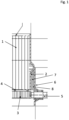
- the Figure 1 shows a sectional view of a device for exhaust gas aftertreatment.
- a honeycomb body 1 formed from a metallic matrix, is arranged centrally.
- the honeycomb body 1 is housed in an inner casing 2, which secures the matrix, protects it from fanning out and rolling up, and simultaneously protects the matrix from mechanical influences.
- Honeycomb bodies of this design are known in many different forms in the prior art.
- a heating disc 3 is arranged in front of the honeycomb body 1 and is connected to the honeycomb body 1 via support pins 4.
- the heating disc 3 is connected to a voltage source via the electrical feedthrough 5 shown and can thus be supplied with current, whereby heating is achieved.
- the honeycomb body 1 with its inner shell 2 is inserted into an outer shell 6 and permanently connected to it, for example, by soldering.
- An air gap 7 is formed between the outer shell 6 and the inner shell 2. This can be deliberately created as a result of the component geometry or can also be formed as a result of tolerances between the components. Air gaps are also conceivable between all components of the device.
- the air gap 7 is in the embodiment of the Figure 1 filled with a filler 8 so that nothing can penetrate into the air gap 7, particularly from the side facing the heating disc 3.
- the washcoat, with which the matrix of the honeycomb body 1 is coated, is, for example, pressed into the honeycomb body using positive pressure and/or drawn through it using negative pressure.
- the honeycomb body 1 can also be rinsed with the washcoat. With all of these methods, it is very likely that washcoat would penetrate the air gap 7 if it is not sealed.
- the filler can be introduced into the air gap 7 in a targeted manner, for example by means of an injection needle, in order to fill it and in particular to fill the open cross-section.
Landscapes
- Engineering & Computer Science (AREA)
- Chemical & Material Sciences (AREA)
- Chemical Kinetics & Catalysis (AREA)
- Combustion & Propulsion (AREA)
- General Engineering & Computer Science (AREA)
- Mechanical Engineering (AREA)
- Health & Medical Sciences (AREA)
- Toxicology (AREA)
- Materials Engineering (AREA)
- Organic Chemistry (AREA)
- Biomedical Technology (AREA)
- Environmental & Geological Engineering (AREA)
- Analytical Chemistry (AREA)
- General Chemical & Material Sciences (AREA)
- Oil, Petroleum & Natural Gas (AREA)
- Physics & Mathematics (AREA)
- Thermal Sciences (AREA)
- Catalysts (AREA)
- Exhaust Gas After Treatment (AREA)
Description
- Verfahren zur Verbesserung der Beschichtung eines Wabenkörpers mit einer katalytisch aktiven Beschichtung
- Die Erfindung betrifft ein Verfahren zur Herstellung einer Vorrichtung zur Nachbehandlung von Abgasen und zur Beschichtung eines in der Vorrichtung vorgesehenen Wabenkörpers mit einer katalytisch aktiven Oberflächenbeschichtung, wobei der Wabenkörper aus einer Mehrzahl von metallischen zumindest teilweise strukturierten Folien gebildet ist, die aufeinander gestapelt und aufgewickelt sind, so dass der Wabenkörper eine Mehrzahl von entlang einer Hauptdurchströmungsrichtung durchströmbare Strömungskanäle ausbildet, wobei der Wabenkörper in einem Innenmantel aufgenommen ist und mit diesem dauerhaltbar verbunden ist, wobei der Innenmantel in einem als Gehäuse dienenden Außenmantel angeordnet ist und mit diesem dauerhaltbar verbunden ist.
- Wabenkörper für Katalysatoren zur Abgasnachbehandlung von Verbrennungsmotoren weisen eine Mehrzahl von entlang einer Hauptdurchströmungsrichtung durchströmbaren Strömungskanäle auf. Wabenkörper, insbesondere Wabenkörper aus Metall, sind durch eine Vielzahl von glatten und/oder zumindest teilweise strukturierten Metallfolien gebildet, die aufeinandergestapelt und zum endgültigen Wabenkörper aufgewickelt sind. Die aus den Metallfolien gebildete Matrix wird zur Stabilisierung und zum Zwecke des Schutzes vor mechanischen Störeinflüssen in ein Gehäuse eingesetzt und mit diesem dauerhaltbar verbunden.
- Das Gehäuse ist im einfachsten Fall durch ein Rohr gebildet, welches dazu ausgebildet ist, die Matrix in seinem Inneren aufzunehmen. Eine weitere Funktion des Gehäuses ist es, die Durchströmung des Wabenkörpers sicherzustellen und insbesondere das Vorbeiströmen von Abgas am Wabenkörper zu vermeiden.
- Die Befestigung der Matrix im Gehäuse muss einerseits dauerhaltbar erfolgen, gleichzeitig soll das Gehäuse möglichst leicht und somit dünnwandig aufgebaut sein. Einige Ausführungsformen von Katalysatoren weisen einen Innenmantel auf, welcher die Matrix direkt aufnimmt. Der Innenmantel ist dann über geeignete Abstützungen gegenüber dem Gehäuse beziehungsweise dem Außenmantel abgestützt.
- Die
US 2017/369123 A1 offenbart einen Katalysator zur Behandlung von Abgasen aus einem Motorradmotor. Der Katalysator umfasst ein Gehäuse mit einem stromaufwärts gelegenen Ende und einem stromabwärts gelegenen Ende. Der Gehäusekörper erstreckt sich zwischen dem stromaufwärts gelegenen Ende und dem stromabwärts gelegenen Ende. Ein Katalysatormantel ist innerhalb des Gehäusekörpers so angeordnet, dass ein Hohlraum zwischen dem Katalysatormantel und dem Gehäusekörper gebildet wird. In dem Katalysatormantel ist ein Katalysator angeordnet. In dem Hohlraum zwischen dem Gehäusekörper und dem Katalysatormantel ist ein Isolator angeordnet. - Die
US 2019/112960 A1 offenbart eine Katalysatorvorrichtung, welche einen Katalysatorträger, einen rohrförmigen Abschnitt, der den Katalysatorträger aufnimmt, eine Haltematte, die den Katalysatorträger hält, einen Isolator, der über der äußeren Umfangsfläche des rohrförmigen Abschnitts vorgesehen ist, und ein Wärmeisolierelement, das zwischen dem Isolator und dem rohrförmigen Abschnitt angeordnet ist, aufweist. Der Bereich der äußeren Umfangsfläche des rohrförmigen Teils zwischen dem stromaufwärts gelegenen Ende und dem stromabwärts gelegenen Ende in Strömungsrichtung des Abgases ist in zwei Unterbereiche unterteilt, die in Richtung der Achse des rohrförmigen Teils angeordnet sind. - Die
WO 2015/013545 A1 offenbart ein Verfahren zur Bildung beschichteter Substrate zur Verwendung in Katalysatoren sowie Waschmittelzusammensetzungen. Weiterhin offenbart die Druckschrift ein Verfahren, das zur Herstellung der beschichteten Substrate geeignet ist, und die dadurch gebildeten beschichteten Substrate, bei denen in einigen Fällen eisenausgetauschte Zeolithteilchen verwendet werden, die eine verbesserte Leistung wie niedrigere Abgastemperaturen und geringere Schadstoffwerte in Abgasen bieten. Das katalytische Material wird durch ein plasmagestütztes Verfahren hergestellt, das eine geringere Tendenz zur Migration des Trägermaterials bei hohen Temperaturen aufweist und somit weniger anfällig für die Alterung des Katalysators nach längerem Gebrauch ist. Außerdem werden Katalysatoren mit den beschichteten Substraten offenbart, die im Vergleich zu Katalysatoren, die mit Hilfe von Lösungschemie auf Substraten abgeschieden werden, vorteilhafte Eigenschaften aufweisen. - Die
US 2020/171529 A1 offenbart eine Vorrichtung und ein Verfahren zur Beschichtung von Substraten mit Washcoats. Insbesondere geht es um die Beschichtung von Substraten, die zur Abgasreinigung verwendet werden. - Nachteilig an den Vorrichtungen im Stand der Technik ist insbesondere, dass zwischen den einzelnen Elementen eines Katalysators, zum Beispiel zwischen dem Innenmantel und dem Außenmantel, Luftspalte entstehen können, welche bei der Beschichtung der Matrix mit einem katalytisch aktiven Material, dem sogenannten Washcoat, durch dieses Material zugesetzt werden können. Durch mechanische Erschütterungen sowie thermische Einflüsse im Betrieb kann sich dieses in den Luftspalten festgesetzte Material lösen, wodurch es zu Beschädigungen und/oder der katalytischen Deaktivierung nachgelagerter Komponenten zur Abgasnachbehandlung kommen kann.
- Darüber hinaus ist es nachteilig, dass der in einem Spalt eingebrachte Washcoat nicht an der katalytischen Reaktion am Wabenkörper teilnimmt und er somit ohne Funktion ist. Die tatsächlich benötigte Menge des Washcoats für die Beschichtung des Wabenkörpers ist somit eigentlich niedriger. Der unnötige Mehrverbrauch ist insbesondere ein Nachteil, wenn der Washcoat Edelmetalle aufweist, welche hochpreisig sind.
- Daher ist es die Aufgabe der vorliegenden Erfindung ein Verfahren zu schaffen, welches es ermöglicht den Wabenkörper in einem Gehäuse möglichst genau mit der minimal notwendigen Menge an Washcoat zu beschichten und insbesondere das Einbringen von Washcoat in Bereiche zu vermeiden, welche nicht an der katalytischen Reaktion teilnehmen.
- Die Aufgabe hinsichtlich des Verfahrens wird durch ein Verfahren mit den Merkmalen von Anspruch 1 gelöst.
- Ein Ausführungsbeispiel der Erfindung betrifft ein Verfahren zur Herstellung einer Vorrichtung zur Nachbehandlung von Abgasen und zur Beschichtung eines in der Vorrichtung vorgesehenen Wabenkörpers mit einer katalytisch aktiven Oberflächenbeschichtung, wobei der Wabenkörper aus einer Mehrzahl von metallischen zumindest teilweise strukturierten Folien gebildet ist, die aufeinander gestapelt und aufgewickelt sind, so dass der Wabenkörper eine Mehrzahl von entlang einer Hauptdurchströmungsrichtung durchströmbare Strömungskanäle ausbildet, wobei der Wabenkörper in einem Innenmantel aufgenommen ist und mit diesem dauerhaltbar verbunden ist, wobei der Innenmantel in einem als Gehäuse dienenden Außenmantel angeordnet ist und mit diesem dauerhaltbar verbunden ist, wobei vor dem Einbringen der katalytisch aktiven Beschichtung in die von dem Wabenkörper ausgebildeten Strömungskanäle eine Luftspalt oder Luftspalte, welche sich zwischen dem Außenmantel und dem Innenmantel ausgebildet haben, durch ein Füllmittel ausgefüllt werden.
- Ein grundsätzliches Verfahren zur Herstellung einer Vorrichtung mit einem Wabenkörper in einem Innenmantel, welcher dauerhaltbar in einem Außenmantel aufgenommen ist, ist aus dem Stand der Technik bekannt. Die Matrix wird durch das Aufeinanderstapeln von Metallfolien, welche zumindest teilweise strukturiert sind, und das anschließende Aufwickeln des so erzeugten Lagenstapels um einen Dorn oder mehrere Dorne erzeugt. Die Matrix des Wabenkörpers wird mit dem Innenmantel beispielweise mittels eines Lötverfahrens verbunden, nachdem die Matrix in den Innenmantel eingesetzt wurde.
- Der Innenmantel ist bevorzugt sehr dünn ausgestaltet und dient im Wesentlichen der Stabilisierung der Matrix, so dass diese nicht aufrollt oder auffächert.
- Der Wabenkörper wird nachfolgend in ein als Abschluss zur Umwelt dienendes Gehäuse, welches durch einen Außenmantel gebildet ist, eingesetzt und mit diesem dauerhaltbar verbunden, beispielsweise durch Löten. Der Außenmantel ist wesentlich dicker als der Innenmantel und dient der Strömungsleitung des Abgases, dem mechanischen Schutz des Wabenkörpers und der Anbindung an weitere Komponenten zur Abgasnachbehandlung.
- Insbesondere zwischen dem Innenmantel und dem Außenmantel können sich aufgrund von Toleranzen oder einfach aufgrund der Geometrie der einzelnen Bauteile Spalte ausbilden. Regelmäßig entsteht hierbei ein in Umfangsrichtung vollständig umlaufender Spalt zwischen dem Innenmantel und dem Außenmantel. Der Luftspalt erstreckt sich dabei in axialer Richtung regelmäßig nur entlang eines Teilabschnitts an dem Innenmantel und Außenmantel anliegen. Dieser Luftspalt bildet einen Hohlraum aus, der aus dem im Außenmantel eingeschlossenen Volumen, der Abgasströmungsstrecke, zugänglich ist.
- Zur Beschichtung der Matrix wird ein Beschichtungsmaterial beispielsweise durch Überdruck oder durch Unterdruck durch die Strömungskanäle der Matrix gedrückt oder gesaugt. Dadurch wird die Oberfläche der Strömungskanäle beschichtet und somit eine katalytisch aktive Oberfläche geschaffen, an welcher die chemische Reaktion mit dem Abgas stattfindet. Durch das Einbringen des Beschichtungsmaterials kann es vorkommen, dass auch Strukturen außerhalb der Matrix mit dem Beschichtungsmaterial beaufschlagt werden, insbesondere kann das Beschichtungsmaterial in den ausgebildeten Luftspalt eindringen und dort verbleiben. Hierdurch wird einerseits die in der Vorrichtung verbleibende Menge des Beschichtungsmaterials deutlich erhöht und weiterhin kann sich das Beschichtungsmaterial im Betrieb aus dem Luftspalt lösen, wodurch es im Abgasstrom mitgeführt wird und gegebenenfalls in Strömungsrichtung nachgelagerte Komponenten zur Abgasnachbehandlung beschädigt. Insbesondere kann es zu einer sogenannten Vergiftung kommen, wenn katalytisch aktives Material in Kontakt mit andersartigem katalytisch aktivem Material auf anderen Wabenkörpern kommt. Es kann dann zu einer chemischen Reaktion kommen, welche einen nachgelagerten Katalysator ganz oder zumindest teilweise zerstört. Daher ist es dringend zu vermeiden, dass katalytisch aktives Beschichtungsmaterial sich in Bereichen ablagert, die nicht zur Beschichtung vorgesehen sind.
- Um das Eindringen des Beschichtungsmaterial in den Luftspalt zu verhindern, wird dieser vor dem Einbringen des Beschichtungsmaterials mit einem Füllmittel aufgefüllt. Dieses Füllmittel kann beispielsweise mit einer Injektionsnadel in den Spalt eingebracht werden.
- Das Füllmittel verfestigt sich im Luftspalt so sehr, dass es durch das Einbringen des Beschichtungsmittels nicht verdrängt wird und nicht eigenständig aus dem Luftspalt hinausläuft oder aus diesem hinausgesaugt wird.
- Das Füllmittel kann bevorzugt durch eine Öffnung von außerhalb des Außenmantels in den Luftspalt eingebracht werden. Alternativ kann es vom offenen Querschnitt des Außenmantels direkt in den Luftspalt eingebracht werden.
- Besonders vorteilhaft ist es, wenn das Füllmittel eine gelartige organische Masse ist. Eine gelartige organische Masse ist vorteilhaft, um sicherzustellen, dass der gesamte Luftspalt schnell und einfach ausgefüllt werden kann, indem das Füllmittel direkt in den Luftspalt eingespritzt wird. Das Füllmittel hat bevorzugt Materialeigenschaften, die ein Einspritzen in den Luftspalt erlauben. Darüber hinaus ist das Füllmittel derart beschaffen, dass es eine ausreichende Festigkeit innerhalb des Luftspaltes erreicht, so dass es nicht einfach aus dem Luftspalt herausgesaugt oder herausgedrückt werden kann.
- Auch ist es vorteilhaft, wenn das Füllmittel in die Spalte eingebracht wird, bevor die Vorrichtung einer weiteren Wärmebehandlung, wie beispielswiese dem Trocknen oder dem Kalzinieren unterzogen wird. Dies ist vorteilhaft, da durch das Trocknen oder das Kalzieren eine deutliche Temperaturerhöhung der Vorrichtung erreicht wird, und das Füllmittel bevorzugt eine begrenzte thermische Stabilität aufweist, so dass es ab einer gewissen Temperatureinwirkung nicht mehr stabil ist beziehungsweise sich vollständig auflöst.
- Ein bevorzugtes Ausführungsbeispiel ist dadurch gekennzeichnet, dass das Füllmittel nach dem Einbringen der katalytisch aktiven Beschichtung aus dem Luftspalt entfernt wird. Dies ist vorteilhaft, um das Füllmittel vor dem Inbetriebnehmen der Vorrichtung zu entfernen. Andernfalls könnte sich das Füllmittel im Betrieb unter den mechanischen Belastungen und den thermischen Wechseleinwirkungen aus dem Luftspalt lösen. Und Strömungskanäle verblocken oder zu einer Beschädigung von Komponenten im Abgasstrang führen.
- Auch ist es zu bevorzugen, wenn das Füllmittel durch einen thermischen Prozess aus dem Luftspalt entfernt wird. Dies ist vorteilhaft, da der Wabenkörper beziehungsweise die gesamte Vorrichtung regelmäßig mehrere Prozessschritte durchläuft, in welchen stark erhöhte Temperaturen auf diese einwirken. Es kann somit, ohne einen zusätzlichen Arbeitsschritt vorzusehen, sichergestellt werden, dass das Füllmittel über eine für das Füllmittel kritische Temperatur erwärmt wird und sich das Füllmittel dadurch auflöst.
- Darüber hinaus ist es vorteilhaft, wenn das Ausfüllen des Luftspaltes derart erfolgt, dass der der Einbringstelle, durch welche die katalytisch aktive Beschichtung eingebracht wird, zugewandte Öffnungsquerschnitt von dem Füllmittel verschlossen wird. Dies ist besonders wichtig, um sicherzustellen, dass sich keinerlei Beschichtungsmaterial im Luftspalt festsetzen kann. Durch den Verschluss des Öffnungsquerschnitts ist dies sichergestellt.
- In einer bevorzugten Ausführung kann das Füllmittel derart gestaltet sein, dass es sich nach dem Einbringen ausdehnt und gegebenenfalls eine Teilmenge des eingebrachten Füllmittels aus dem Luftspalt hinausquillt, um sicherzustellen, dass keinerlei Beschichtungsmaterial in den Luftspalt geraten kann.
- Vorteilhafte Weiterbildungen der vorliegenden Erfindung sind in den Unteransprüchen und in der nachfolgenden Figurenbeschreibung beschrieben.
- Im Folgenden wird die Erfindung anhand eines Ausführungsbeispiels unter Bezugnahme auf die Zeichnung detailliert erläutert. In der Zeichnung zeigt:
- Fig. 1
- eine Schnittansicht durch einen Wabenkörper, welcher in einem Außenmantel aufgenommen ist, wobei der zwischen dem Innenmantel des Wabenkörpers und dem Außenmantel ausgebildete Luftspalt mit einem Füllmittel ausgefüllt ist.
- Die
Figur 1 zeigt eine Vorrichtung zur Abgasnachbehandlung in einer Schnittansicht. Zentral ist ein Wabenkörper 1 angeordnet, welcher aus einer metallischen Matrix gebildet ist. Der Wabenkörper 1 ist in einem Innenmantel 2 aufgenommen, welcher die Matrix fixiert, gegen auffächern und aufrollen schützt und gleichzeitig die Matrix vor mechanischen Einflüssen schützt. Wabenkörper dieser Bauart sind im Stand der Technik in vielfältiger Weise bekannt. - In der Abbildung der
Figur 1 ist dem Wabenkörper 1 eine Heizscheibe 3 vorgelagert, welche über Stützstifte 4 mit dem Wabenkörper 1 verbunden ist. Die Heizscheibe 3 ist über die gezeigte elektrische Durchführung 5 mit einer Spannungsquelle verbunden und kann somit bestromt werden, wodurch eine Aufheizung erreicht wird. - Der Wabenkörper 1 mit seinem Innenmantel 2 ist in einen Außenmantel 6 eingesetzt und mit diesem dauerhaltbar beispielsweise durch Löten verbunden. Zwischen dem Außenmantel 6 und dem Innenmantel 2 ist ein Luftspalt 7 ausgebildet. Diese kann infolge der Bauteilgeometrie gezielt entstehen, oder aber auch infolge von Toleranzen zwischen den Bauteilen ausgebildet werden. Auch sind Luftspalte grundsätzlich zwischen allen Komponenten der Vorrichtung denkbar.
- Der Luftspalt 7 ist im Ausführungsbeispiel der
Figur 1 durch ein Füllmittel 8 ausgefüllt, so dass insbesondere von der der Heizscheibe 3 zugewandten Seite nichts in dien Luftspalt 7 eindringen kann. - Der Washcoat, mit welchem die Matrix des Wabenkörpers 1 beschichtet wird, wird beispielsweise mit Überdruck in den Wabenkörper gedrückt und/oder mit Unterdruck durch diesen gezogen. Auch kann der Wabenkörper 1 mit dem Washcoat gespült werden. Bei alle diesen Verfahren ist es sehr wahrscheinlich, dass Washcoat in den Luftspalt 7 eindringen würde, wenn dieser nicht verschlossen ist.
- Das Füllmittel kann beispielsweise mittels einer Injektionsnadel gezielt in den Luftspalt 7 eingebracht werden, um diesen auszufüllen und insbesondere den offenen Querschnitt auszufüllen.
- Das Ausführungsbeispiel der
Figur 1 weist insbesondere keinen beschränkenden Charakter auf und dient der Verdeutlichung des Erfindungsgedankens.
Claims (6)
- Verfahren zur Herstellung einer Vorrichtung zur Nachbehandlung von Abgasen und zur Beschichtung eines in der Vorrichtung vorgesehenen Wabenkörpers (1) mit einer katalytisch aktiven Oberflächenbeschichtung, wobei der Wabenkörper (1) aus einer Mehrzahl von metallischen zumindest teilweise strukturierten Folien gebildet ist, die aufeinander gestapelt und aufgewickelt sind, so dass der Wabenkörper eine Mehrzahl von entlang einer Hauptdurchströmungsrichtung durchströmbare Strömungskanäle ausbildet, wobei der Wabenkörper in einem Innenmantel (2) aufgenommen ist und mit diesem dauerhaltbar verbunden ist, wobei der Innenmantel (2) in einem als Gehäuse dienenden Außenmantel (6) angeordnet ist und mit diesem dauerhaltbar verbunden ist, dadurch gekennzeichnet , dass vor dem Einbringen der katalytisch aktiven Beschichtung in die von dem Wabenkörper (1) ausgebildeten Strömungskanäle ein Luftspalt (7) oder Luftspalte, welche sich zwischen dem Außenmantel (6) und dem Innenmantel (2) ausgebildet haben, durch ein Füllmittel (8) ausgefüllt werden.
- Verfahren nach Anspruch 1, dadurch gekennzeichnet , dass das Füllmittel (8) eine gelartige organische Masse ist.
- Verfahren nach einem der vorhergehenden Ansprüche, dadurch gekennzeichnet , dass das Füllmittel (8) in die Luftspalte (7) eingebracht wird, bevor die Vorrichtung einer weiteren Wärmebehandlung, wie beispielswiese dem Trocknen oder dem Kalzinieren unterzogen wird.
- Verfahren nach einem der vorhergehenden Ansprüche, dadurch gekennzeichnet , dass das Füllmittel (8) nach dem Einbringen der katalytisch aktiven Beschichtung aus dem Luftspalt (7) entfernt wird.
- Verfahren nach einem der vorhergehenden Ansprüche, dadurch gekennzeichnet , dass das Füllmittel (8) durch einen thermischen Prozess aus dem Luftspalt (7) entfernt wird.
- Verfahren nach einem der vorhergehenden Ansprüche, dadurch gekennzeichnet, dass das Ausfüllen des Luftspaltes (7) derart erfolgt, dass der der Einbringstelle, durch welche die katalytisch aktive Beschichtung eingebracht wird, zugewandte Öffnungsquerschnitt von dem Füllmittel (8) verschlossen wird.
Applications Claiming Priority (2)
| Application Number | Priority Date | Filing Date | Title |
|---|---|---|---|
| DE102021208131.2A DE102021208131B3 (de) | 2021-07-28 | 2021-07-28 | Verfahren zur Verbesserung der Beschichtung eines Wabenkörpers mit einer katalytisch aktiven Beschichtung |
| PCT/EP2022/069901 WO2023006452A1 (de) | 2021-07-28 | 2022-07-15 | Verfahren zur verbesserung der beschichtung eines wabenkörpers mit einer katalytisch aktiven beschichtung |
Publications (3)
| Publication Number | Publication Date |
|---|---|
| EP4377560A1 EP4377560A1 (de) | 2024-06-05 |
| EP4377560B1 true EP4377560B1 (de) | 2025-04-16 |
| EP4377560B8 EP4377560B8 (de) | 2025-05-28 |
Family
ID=82656736
Family Applications (1)
| Application Number | Title | Priority Date | Filing Date |
|---|---|---|---|
| EP22744756.2A Active EP4377560B8 (de) | 2021-07-28 | 2022-07-15 | Verfahren zur verbesserung der beschichtung eines wabenkörpers mit einer katalytisch aktiven beschichtung |
Country Status (7)
| Country | Link |
|---|---|
| US (1) | US20240375094A1 (de) |
| EP (1) | EP4377560B8 (de) |
| JP (1) | JP7711306B2 (de) |
| KR (1) | KR20240031414A (de) |
| CN (1) | CN117716115B (de) |
| DE (1) | DE102021208131B3 (de) |
| WO (1) | WO2023006452A1 (de) |
Family Cites Families (15)
| Publication number | Priority date | Publication date | Assignee | Title |
|---|---|---|---|---|
| JPS62294445A (ja) * | 1986-06-13 | 1987-12-21 | Toyota Motor Corp | モノリス担体の外周部セルの目詰め方法 |
| JP2618161B2 (ja) * | 1992-09-07 | 1997-06-11 | 日産自動車株式会社 | 金属ハニカム触媒コンバータとその製造方法 |
| JP3072281B2 (ja) * | 1997-04-10 | 2000-07-31 | 三菱化学株式会社 | 触媒コンバーター |
| JP4171939B2 (ja) * | 1998-07-27 | 2008-10-29 | トヨタ自動車株式会社 | 触媒コンバータの製造方法 |
| JP4384340B2 (ja) * | 2000-08-14 | 2009-12-16 | 株式会社アイシーティー | 触媒の製造方法 |
| DE10257113A1 (de) * | 2002-12-05 | 2004-06-24 | Emitec Gesellschaft Für Emissionstechnologie Mbh | Partikelfalle mit beschichteter Faserlage |
| US7132150B2 (en) * | 2003-08-14 | 2006-11-07 | Corning Incorporated | Porous ceramic filters with catalyst coatings |
| JPWO2008126307A1 (ja) * | 2007-03-30 | 2010-07-22 | イビデン株式会社 | 触媒担持体および触媒担持体の製造方法 |
| WO2009014025A1 (ja) * | 2007-07-26 | 2009-01-29 | Nippon Shokubai Co., Ltd. | 排ガス処理装置 |
| DE102011119517B4 (de) * | 2011-11-25 | 2017-02-09 | Oberland Mangold Gmbh | Wabenkörper sowie Verfahren zu seiner Herstellung |
| CN105592921A (zh) * | 2013-07-25 | 2016-05-18 | Sdc材料公司 | 用于催化转化器的洗涂层和经涂覆基底及其制造和使用方法 |
| US10465585B2 (en) | 2015-03-23 | 2019-11-05 | Corning Incorporated | Exhaust gas treatment article and methods of manufacturing same |
| US10526043B2 (en) * | 2016-06-24 | 2020-01-07 | V&H Performance, Llc | Motorcycle exhaust with catalytic converter |
| JP6838542B2 (ja) * | 2017-10-12 | 2021-03-03 | トヨタ自動車株式会社 | 触媒装置 |
| GB201819455D0 (en) * | 2018-11-29 | 2019-01-16 | Johnson Matthey Plc | Apparatus and method for coating substrates with washcoats |
-
2021
- 2021-07-15 US US18/291,766 patent/US20240375094A1/en active Pending
- 2021-07-28 DE DE102021208131.2A patent/DE102021208131B3/de active Active
-
2022
- 2022-07-15 WO PCT/EP2022/069901 patent/WO2023006452A1/de not_active Ceased
- 2022-07-15 EP EP22744756.2A patent/EP4377560B8/de active Active
- 2022-07-15 JP JP2024505186A patent/JP7711306B2/ja active Active
- 2022-07-15 KR KR1020247005640A patent/KR20240031414A/ko active Pending
- 2022-07-15 CN CN202280052664.5A patent/CN117716115B/zh active Active
Also Published As
| Publication number | Publication date |
|---|---|
| JP7711306B2 (ja) | 2025-07-22 |
| US20240375094A1 (en) | 2024-11-14 |
| KR20240031414A (ko) | 2024-03-07 |
| EP4377560B8 (de) | 2025-05-28 |
| EP4377560A1 (de) | 2024-06-05 |
| CN117716115A (zh) | 2024-03-15 |
| CN117716115B (zh) | 2026-07-17 |
| DE102021208131B3 (de) | 2022-12-01 |
| WO2023006452A1 (de) | 2023-02-02 |
| JP2024530445A (ja) | 2024-08-21 |
Similar Documents
| Publication | Publication Date | Title |
|---|---|---|
| DE69727420T2 (de) | Sauerstoffsensorelement und sein Herstellungsverfahren | |
| EP0509207A1 (de) | Vorrichtung zum katalytischen Entgiften von Abgasen | |
| DE102020130657A1 (de) | Abgasheizvorrichtung mit einem Heizelement aus Metallschaum | |
| EP4314508B1 (de) | Vorrichtung zur abgasnachbehandlung und verfahren zum herstellen dieser | |
| EP2904229A1 (de) | Elektrisch beheizbarer, aus keramischem material extrudierter wabenkörper | |
| DE102007025417A1 (de) | Elektrisch beheizbare Wabenkörper-Anordnung mit Stützstiften | |
| EP1272745B1 (de) | Gehäuse mit passivierungsschicht und verfahren zur herstellung eines katalysator-trägerkörpers mit einem solchen gehäuse | |
| EP1527262B1 (de) | Abgasfilter und verfahren zum reinigen eines abgases | |
| EP1831511B1 (de) | Wabenkörper mit zumindest teilweise keramischer wabenstruktur und aufnahme für messfühler und verfahren zur herstellung eines solchen wabenkörpers | |
| EP2260190B1 (de) | Wabenkörper und verfahren zur herstellung eines gelöteten wabenkörpers | |
| DE102007056213A1 (de) | Verfahren zur Herstellung eines von Abgas durchströmbaren Formkörpers sowie Abgasanlage einer Brennkraftmaschine | |
| DE102021208131B3 (de) | Verfahren zur Verbesserung der Beschichtung eines Wabenkörpers mit einer katalytisch aktiven Beschichtung | |
| DE10190162B4 (de) | Katalysator-Trägerkörper mit einer Dehnungen erlaubenden Manschette mit Mikrostrukturen | |
| WO2009000667A2 (de) | Herstellungsverfahren und katalysatorelement mit axial veränderlicher katalytischer beschichtung | |
| WO2008098727A1 (de) | Abgasführende vorrichtung, insbesondere abgasreinigungsvorrichtung, sowie verfahren zur herstellung einer abgasführenden vorrichtung | |
| DE10018641A1 (de) | Gehäuse mit keramischer Innenschicht für einen Katalysatorträgerkörper und Verfahren zur Herstellung eines Katalysator-Trägerkörpers mit einem solchen Gehäuse | |
| EP1229219A2 (de) | Vorrichtung zum Reinigen von Abgasen eines Verbrennungsmotors und Verfahren zu seiner Herstellung | |
| EP4359652B1 (de) | Vorrichtung zur abgasnachbehandlung mit geringen hohlräumen | |
| WO2007082668A1 (de) | Abgasreinigungsvorrichtung sowie verfahren zur herstellung einer abgasreinigungsvorrichtung | |
| DE102021213769A1 (de) | Vorrichtung zur Abgasnachbehandlung mit geringen Hohlräumen | |
| WO2004018098A1 (de) | Verfahren und vorrichtung zur herstellung von wabenkörpern und wabenkörper | |
| DE10313155B4 (de) | Verfahren zur Herstellung eines Abgaskatalysators | |
| DE102018119399B4 (de) | Reduktionsmitteleinspritzvorrichtung | |
| DE10027807A1 (de) | Blech mit Barriere für einen Wabenkörper | |
| DE102014102619A1 (de) | Reinigungs-Strömungskörper, Reinigungsvorrichtung und Verfahren zum Herstellen eines Reinigungs-Strömungskörpers |
Legal Events
| Date | Code | Title | Description |
|---|---|---|---|
| STAA | Information on the status of an ep patent application or granted ep patent |
Free format text: STATUS: UNKNOWN |
|
| STAA | Information on the status of an ep patent application or granted ep patent |
Free format text: STATUS: THE INTERNATIONAL PUBLICATION HAS BEEN MADE |
|
| PUAI | Public reference made under article 153(3) epc to a published international application that has entered the european phase |
Free format text: ORIGINAL CODE: 0009012 |
|
| STAA | Information on the status of an ep patent application or granted ep patent |
Free format text: STATUS: REQUEST FOR EXAMINATION WAS MADE |
|
| 17P | Request for examination filed |
Effective date: 20240228 |
|
| AK | Designated contracting states |
Kind code of ref document: A1 Designated state(s): AL AT BE BG CH CY CZ DE DK EE ES FI FR GB GR HR HU IE IS IT LI LT LU LV MC MK MT NL NO PL PT RO RS SE SI SK SM TR |
|
| DAV | Request for validation of the european patent (deleted) | ||
| DAX | Request for extension of the european patent (deleted) | ||
| GRAP | Despatch of communication of intention to grant a patent |
Free format text: ORIGINAL CODE: EPIDOSNIGR1 |
|
| STAA | Information on the status of an ep patent application or granted ep patent |
Free format text: STATUS: GRANT OF PATENT IS INTENDED |
|
| INTG | Intention to grant announced |
Effective date: 20241112 |
|
| GRAS | Grant fee paid |
Free format text: ORIGINAL CODE: EPIDOSNIGR3 |
|
| GRAA | (expected) grant |
Free format text: ORIGINAL CODE: 0009210 |
|
| STAA | Information on the status of an ep patent application or granted ep patent |
Free format text: STATUS: THE PATENT HAS BEEN GRANTED |
|
| REG | Reference to a national code |
Ref country code: DE Ref legal event code: R081 Ref document number: 502022003611 Country of ref document: DE Owner name: SCHAEFFLER TECHNOLOGIES AG & CO. KG, DE Free format text: FORMER OWNER: VITESCO TECHNOLOGIES GMBH, 93055 REGENSBURG, DE |
|
| AK | Designated contracting states |
Kind code of ref document: B1 Designated state(s): AL AT BE BG CH CY CZ DE DK EE ES FI FR GB GR HR HU IE IS IT LI LT LU LV MC MK MT NL NO PL PT RO RS SE SI SK SM TR |
|
| REG | Reference to a national code |
Ref country code: GB Ref legal event code: FG4D Free format text: NOT ENGLISH |
|
| REG | Reference to a national code |
Ref country code: CH Ref legal event code: PK Free format text: BERICHTIGUNG B8 Ref country code: CH Ref legal event code: EP |
|
| RAP2 | Party data changed (patent owner data changed or rights of a patent transferred) |
Owner name: SCHAEFFLER TECHNOLOGIES AG & CO. KG |
|
| REG | Reference to a national code |
Ref country code: IE Ref legal event code: FG4D Free format text: LANGUAGE OF EP DOCUMENT: GERMAN |
|
| REG | Reference to a national code |
Ref country code: DE Ref legal event code: R096 Ref document number: 502022003611 Country of ref document: DE |
|
| REG | Reference to a national code |
Ref country code: NL Ref legal event code: MP Effective date: 20250416 |
|
| P01 | Opt-out of the competence of the unified patent court (upc) registered |
Free format text: CASE NUMBER: UPC_APP_2347_4377560/2025 Effective date: 20250804 |
|
| PG25 | Lapsed in a contracting state [announced via postgrant information from national office to epo] |
Ref country code: NL Free format text: LAPSE BECAUSE OF FAILURE TO SUBMIT A TRANSLATION OF THE DESCRIPTION OR TO PAY THE FEE WITHIN THE PRESCRIBED TIME-LIMIT Effective date: 20250416 |
|
| PG25 | Lapsed in a contracting state [announced via postgrant information from national office to epo] |
Ref country code: FI Free format text: LAPSE BECAUSE OF FAILURE TO SUBMIT A TRANSLATION OF THE DESCRIPTION OR TO PAY THE FEE WITHIN THE PRESCRIBED TIME-LIMIT Effective date: 20250416 Ref country code: PT Free format text: LAPSE BECAUSE OF FAILURE TO SUBMIT A TRANSLATION OF THE DESCRIPTION OR TO PAY THE FEE WITHIN THE PRESCRIBED TIME-LIMIT Effective date: 20250818 Ref country code: ES Free format text: LAPSE BECAUSE OF FAILURE TO SUBMIT A TRANSLATION OF THE DESCRIPTION OR TO PAY THE FEE WITHIN THE PRESCRIBED TIME-LIMIT Effective date: 20250416 |
|
| PGFP | Annual fee paid to national office [announced via postgrant information from national office to epo] |
Ref country code: DE Payment date: 20250731 Year of fee payment: 4 |
|
| REG | Reference to a national code |
Ref country code: LT Ref legal event code: MG9D |
|
| PG25 | Lapsed in a contracting state [announced via postgrant information from national office to epo] |
Ref country code: GR Free format text: LAPSE BECAUSE OF FAILURE TO SUBMIT A TRANSLATION OF THE DESCRIPTION OR TO PAY THE FEE WITHIN THE PRESCRIBED TIME-LIMIT Effective date: 20250717 Ref country code: NO Free format text: LAPSE BECAUSE OF FAILURE TO SUBMIT A TRANSLATION OF THE DESCRIPTION OR TO PAY THE FEE WITHIN THE PRESCRIBED TIME-LIMIT Effective date: 20250716 |
|
| PG25 | Lapsed in a contracting state [announced via postgrant information from national office to epo] |
Ref country code: PL Free format text: LAPSE BECAUSE OF FAILURE TO SUBMIT A TRANSLATION OF THE DESCRIPTION OR TO PAY THE FEE WITHIN THE PRESCRIBED TIME-LIMIT Effective date: 20250416 |
|
| PG25 | Lapsed in a contracting state [announced via postgrant information from national office to epo] |
Ref country code: BG Free format text: LAPSE BECAUSE OF FAILURE TO SUBMIT A TRANSLATION OF THE DESCRIPTION OR TO PAY THE FEE WITHIN THE PRESCRIBED TIME-LIMIT Effective date: 20250416 |
|
| PG25 | Lapsed in a contracting state [announced via postgrant information from national office to epo] |
Ref country code: HR Free format text: LAPSE BECAUSE OF FAILURE TO SUBMIT A TRANSLATION OF THE DESCRIPTION OR TO PAY THE FEE WITHIN THE PRESCRIBED TIME-LIMIT Effective date: 20250416 |
|
| PGFP | Annual fee paid to national office [announced via postgrant information from national office to epo] |
Ref country code: FR Payment date: 20250725 Year of fee payment: 4 Ref country code: AT Payment date: 20251020 Year of fee payment: 4 |
|
| PG25 | Lapsed in a contracting state [announced via postgrant information from national office to epo] |
Ref country code: RS Free format text: LAPSE BECAUSE OF FAILURE TO SUBMIT A TRANSLATION OF THE DESCRIPTION OR TO PAY THE FEE WITHIN THE PRESCRIBED TIME-LIMIT Effective date: 20250716 |
|
| PG25 | Lapsed in a contracting state [announced via postgrant information from national office to epo] |
Ref country code: IS Free format text: LAPSE BECAUSE OF FAILURE TO SUBMIT A TRANSLATION OF THE DESCRIPTION OR TO PAY THE FEE WITHIN THE PRESCRIBED TIME-LIMIT Effective date: 20250816 |
|
| PG25 | Lapsed in a contracting state [announced via postgrant information from national office to epo] |
Ref country code: LV Free format text: LAPSE BECAUSE OF FAILURE TO SUBMIT A TRANSLATION OF THE DESCRIPTION OR TO PAY THE FEE WITHIN THE PRESCRIBED TIME-LIMIT Effective date: 20250416 |
|
| PG25 | Lapsed in a contracting state [announced via postgrant information from national office to epo] |
Ref country code: DK Free format text: LAPSE BECAUSE OF FAILURE TO SUBMIT A TRANSLATION OF THE DESCRIPTION OR TO PAY THE FEE WITHIN THE PRESCRIBED TIME-LIMIT Effective date: 20250416 Ref country code: SM Free format text: LAPSE BECAUSE OF FAILURE TO SUBMIT A TRANSLATION OF THE DESCRIPTION OR TO PAY THE FEE WITHIN THE PRESCRIBED TIME-LIMIT Effective date: 20250416 |
|
| REG | Reference to a national code |
Ref country code: DE Ref legal event code: R097 Ref document number: 502022003611 Country of ref document: DE |
|
| PG25 | Lapsed in a contracting state [announced via postgrant information from national office to epo] |
Ref country code: CZ Free format text: LAPSE BECAUSE OF FAILURE TO SUBMIT A TRANSLATION OF THE DESCRIPTION OR TO PAY THE FEE WITHIN THE PRESCRIBED TIME-LIMIT Effective date: 20250416 |
|
| PG25 | Lapsed in a contracting state [announced via postgrant information from national office to epo] |
Ref country code: SK Free format text: LAPSE BECAUSE OF FAILURE TO SUBMIT A TRANSLATION OF THE DESCRIPTION OR TO PAY THE FEE WITHIN THE PRESCRIBED TIME-LIMIT Effective date: 20250416 |
|
| PG25 | Lapsed in a contracting state [announced via postgrant information from national office to epo] |
Ref country code: IT Free format text: LAPSE BECAUSE OF FAILURE TO SUBMIT A TRANSLATION OF THE DESCRIPTION OR TO PAY THE FEE WITHIN THE PRESCRIBED TIME-LIMIT Effective date: 20250416 |
|
| PLBE | No opposition filed within time limit |
Free format text: ORIGINAL CODE: 0009261 |
|
| STAA | Information on the status of an ep patent application or granted ep patent |
Free format text: STATUS: NO OPPOSITION FILED WITHIN TIME LIMIT |
|
| REG | Reference to a national code |
Ref country code: CH Ref legal event code: H13 Free format text: ST27 STATUS EVENT CODE: U-0-0-H10-H13 (AS PROVIDED BY THE NATIONAL OFFICE) Effective date: 20260224 |
|
| REG | Reference to a national code |
Ref country code: CH Ref legal event code: L10 Free format text: ST27 STATUS EVENT CODE: U-0-0-L10-L00 (AS PROVIDED BY THE NATIONAL OFFICE) Effective date: 20260225 |
|
| PG25 | Lapsed in a contracting state [announced via postgrant information from national office to epo] |
Ref country code: RO Free format text: LAPSE BECAUSE OF FAILURE TO SUBMIT A TRANSLATION OF THE DESCRIPTION OR TO PAY THE FEE WITHIN THE PRESCRIBED TIME-LIMIT Effective date: 20250416 |
|
| PG25 | Lapsed in a contracting state [announced via postgrant information from national office to epo] |
Ref country code: LU Free format text: LAPSE BECAUSE OF NON-PAYMENT OF DUE FEES Effective date: 20250715 |
|
| 26N | No opposition filed |
Effective date: 20260119 |
|
| REG | Reference to a national code |
Ref country code: BE Ref legal event code: MM Effective date: 20250731 |
|
| PG25 | Lapsed in a contracting state [announced via postgrant information from national office to epo] |
Ref country code: BE Free format text: LAPSE BECAUSE OF NON-PAYMENT OF DUE FEES Effective date: 20250731 |
|
| PG25 | Lapsed in a contracting state [announced via postgrant information from national office to epo] |
Ref country code: CH Free format text: LAPSE BECAUSE OF NON-PAYMENT OF DUE FEES Effective date: 20250731 |
|
| PG25 | Lapsed in a contracting state [announced via postgrant information from national office to epo] |
Ref country code: LT Free format text: LAPSE BECAUSE OF FAILURE TO SUBMIT A TRANSLATION OF THE DESCRIPTION OR TO PAY THE FEE WITHIN THE PRESCRIBED TIME-LIMIT Effective date: 20250416 |
|
| PG25 | Lapsed in a contracting state [announced via postgrant information from national office to epo] |
Ref country code: IE Free format text: LAPSE BECAUSE OF NON-PAYMENT OF DUE FEES Effective date: 20250715 |
|
| PG25 | Lapsed in a contracting state [announced via postgrant information from national office to epo] |
Ref country code: MC Free format text: LAPSE BECAUSE OF FAILURE TO SUBMIT A TRANSLATION OF THE DESCRIPTION OR TO PAY THE FEE WITHIN THE PRESCRIBED TIME-LIMIT Effective date: 20250416 |
|
| PG25 | Lapsed in a contracting state [announced via postgrant information from national office to epo] |
Ref country code: CY Free format text: LAPSE BECAUSE OF FAILURE TO SUBMIT A TRANSLATION OF THE DESCRIPTION OR TO PAY THE FEE WITHIN THE PRESCRIBED TIME-LIMIT Effective date: 20250416 Ref country code: SE Free format text: LAPSE BECAUSE OF FAILURE TO SUBMIT A TRANSLATION OF THE DESCRIPTION OR TO PAY THE FEE WITHIN THE PRESCRIBED TIME-LIMIT Effective date: 20250416 |