EP4377201B1 - Modularer schaltschutzalgorithmus für ein wasserfahrzeug - Google Patents
Modularer schaltschutzalgorithmus für ein wasserfahrzeug Download PDFInfo
- Publication number
- EP4377201B1 EP4377201B1 EP22748182.7A EP22748182A EP4377201B1 EP 4377201 B1 EP4377201 B1 EP 4377201B1 EP 22748182 A EP22748182 A EP 22748182A EP 4377201 B1 EP4377201 B1 EP 4377201B1
- Authority
- EP
- European Patent Office
- Prior art keywords
- phase
- sps
- shift
- gear
- configuring
- Prior art date
- Legal status (The legal status is an assumption and is not a legal conclusion. Google has not performed a legal analysis and makes no representation as to the accuracy of the status listed.)
- Active
Links
Images


Classifications
-
- B—PERFORMING OPERATIONS; TRANSPORTING
- B63—SHIPS OR OTHER WATERBORNE VESSELS; RELATED EQUIPMENT
- B63H—MARINE PROPULSION OR STEERING
- B63H23/00—Transmitting power from propulsion power plant to propulsive elements
- B63H23/02—Transmitting power from propulsion power plant to propulsive elements with mechanical gearing
- B63H23/08—Transmitting power from propulsion power plant to propulsive elements with mechanical gearing with provision for reversing drive
-
- B—PERFORMING OPERATIONS; TRANSPORTING
- B63—SHIPS OR OTHER WATERBORNE VESSELS; RELATED EQUIPMENT
- B63H—MARINE PROPULSION OR STEERING
- B63H20/00—Outboard propulsion units, e.g. outboard motors or Z-drives; Arrangements thereof on vessels
- B63H20/14—Transmission between propulsion power unit and propulsion element
- B63H20/20—Transmission between propulsion power unit and propulsion element with provision for reverse drive
-
- B—PERFORMING OPERATIONS; TRANSPORTING
- B63—SHIPS OR OTHER WATERBORNE VESSELS; RELATED EQUIPMENT
- B63H—MARINE PROPULSION OR STEERING
- B63H21/00—Use of propulsion power plant or units on vessels
- B63H21/21—Control means for engine or transmission, specially adapted for use on marine vessels
-
- B—PERFORMING OPERATIONS; TRANSPORTING
- B63—SHIPS OR OTHER WATERBORNE VESSELS; RELATED EQUIPMENT
- B63H—MARINE PROPULSION OR STEERING
- B63H23/00—Transmitting power from propulsion power plant to propulsive elements
- B63H23/30—Transmitting power from propulsion power plant to propulsive elements characterised by use of clutches
-
- B—PERFORMING OPERATIONS; TRANSPORTING
- B63—SHIPS OR OTHER WATERBORNE VESSELS; RELATED EQUIPMENT
- B63H—MARINE PROPULSION OR STEERING
- B63H25/00—Steering; Slowing-down otherwise than by use of propulsive elements; Dynamic anchoring, i.e. positioning vessels by means of main or auxiliary propulsive elements
- B63H25/50—Slowing-down means not otherwise provided for
-
- F—MECHANICAL ENGINEERING; LIGHTING; HEATING; WEAPONS; BLASTING
- F02—COMBUSTION ENGINES; HOT-GAS OR COMBUSTION-PRODUCT ENGINE PLANTS
- F02D—CONTROLLING COMBUSTION ENGINES
- F02D31/00—Use of speed-sensing governors to control combustion engines, not otherwise provided for
- F02D31/001—Electric control of rotation speed
-
- F—MECHANICAL ENGINEERING; LIGHTING; HEATING; WEAPONS; BLASTING
- F02—COMBUSTION ENGINES; HOT-GAS OR COMBUSTION-PRODUCT ENGINE PLANTS
- F02D—CONTROLLING COMBUSTION ENGINES
- F02D41/00—Electrical control of supply of combustible mixture or its constituents
- F02D41/02—Circuit arrangements for generating control signals
- F02D41/021—Introducing corrections for particular conditions exterior to the engine
-
- F—MECHANICAL ENGINEERING; LIGHTING; HEATING; WEAPONS; BLASTING
- F16—ENGINEERING ELEMENTS AND UNITS; GENERAL MEASURES FOR PRODUCING AND MAINTAINING EFFECTIVE FUNCTIONING OF MACHINES OR INSTALLATIONS; THERMAL INSULATION IN GENERAL
- F16H—GEARING
- F16H61/00—Control functions within control units of change-speed- or reversing-gearings for conveying rotary motion ; Control of exclusively fluid gearing, friction gearing, gearings with endless flexible members or other particular types of gearing
- F16H61/16—Inhibiting or initiating shift during unfavourable conditions , e.g. preventing forward-reverse shift at high vehicle speed, preventing engine overspeed
-
- B—PERFORMING OPERATIONS; TRANSPORTING
- B63—SHIPS OR OTHER WATERBORNE VESSELS; RELATED EQUIPMENT
- B63H—MARINE PROPULSION OR STEERING
- B63H21/00—Use of propulsion power plant or units on vessels
- B63H21/21—Control means for engine or transmission, specially adapted for use on marine vessels
- B63H2021/216—Control means for engine or transmission, specially adapted for use on marine vessels using electric control means
-
- F—MECHANICAL ENGINEERING; LIGHTING; HEATING; WEAPONS; BLASTING
- F16—ENGINEERING ELEMENTS AND UNITS; GENERAL MEASURES FOR PRODUCING AND MAINTAINING EFFECTIVE FUNCTIONING OF MACHINES OR INSTALLATIONS; THERMAL INSULATION IN GENERAL
- F16H—GEARING
- F16H59/00—Control inputs to control units of change-speed- or reversing-gearings for conveying rotary motion
- F16H59/36—Inputs being a function of speed
- F16H2059/366—Engine or motor speed
-
- F—MECHANICAL ENGINEERING; LIGHTING; HEATING; WEAPONS; BLASTING
- F16—ENGINEERING ELEMENTS AND UNITS; GENERAL MEASURES FOR PRODUCING AND MAINTAINING EFFECTIVE FUNCTIONING OF MACHINES OR INSTALLATIONS; THERMAL INSULATION IN GENERAL
- F16H—GEARING
- F16H61/00—Control functions within control units of change-speed- or reversing-gearings for conveying rotary motion ; Control of exclusively fluid gearing, friction gearing, gearings with endless flexible members or other particular types of gearing
- F16H61/16—Inhibiting or initiating shift during unfavourable conditions , e.g. preventing forward-reverse shift at high vehicle speed, preventing engine overspeed
- F16H2061/165—Preventing reverse gear shifts if vehicle speed is too high for safe shifting
Definitions
- the present disclosure generally relates to shift protection logic and, more specifically, to a modular shift protection algorithm for a marine vessel.
- Modern marine vessels typically employ Marine Propulsion Systems (MPS) to propel the vessel through bodies of water, the systems typically including an engine or power unit to provide power; a transmission system to change directions and to transfer power from the engine to a propeller shaft; the propeller shaft to transfer power from the transmission to a propeller; and the propeller to transfer and convert power from the propeller shaft into linear thrust.
- the MPS may often comprise one or more operator controls, such as a throttle and a gear shift, through which an operator may operatively control the engine and the transmission, respectively.
- the MPS may further comprise a Propulsion Control Processor (PCP) programmed with one or more Shift Protection Sequence(s) (SPS).
- PCP Propulsion Control Processor
- SPS Shift Protection Sequence
- the SPS executes shift protection logic to protect the engine, the transmission, and other components of the marine vessel during gear shifts.
- engine stalling is a common risk that can occur when a vessel traveling in a first direction suddenly shifts into an opposite gear.
- the linear momentum of the vessel imparts a drag load on the propeller, which continues to rotate in the first direction of travel/rotation, and which continues to transfer torque through the propeller shaft to the transmission and engine.
- a sudden gear shift may thus cause a sudden load increase on the engine and potentially stall the engine.
- SPS are useful algorithms for protecting the components of an MPS against engine stalls, clutch failures, and other equipment malfunctions while balancing and/or maximizing a degree of operator control.
- SPS may be particularly applicable in "crash reversal" operations, wherein an operator, in detecting an impending obstacle in the first direction of travel, suddenly “reverses” gears to prevent a "crash".
- Sturdy may require additional sensory and/or communication hardware, preexisting operating data for the engine and the transmission systems, and a knowledgeable technician to configure - all of which may increase an overall cost of the product and increase a complexity for implementation.
- a modular shift protection algorithm capable of incorporating both simple, time-based SPS and complex, operating-variable-based SPS into the same package.
- a modular shift protection algorithm wherein a plurality of SPS of varying degrees of complexity may be optionally, incrementally, and piecewise enabled and configured depending on the needs of the manufacturer or customer.
- US8740659B2 entitled “Outboard Motor Control Apparatus,” describes an apparatus for controlling operation of an outboard motor that has an internal combustion engine equipped with a plurality of cylinders and is configured to switch a shift position between an in-gear position that enables engine's driving force to be transmitted to a propeller and a neutral position that cuts off transmission of the driving force.
- US7377827B1 entitled “Marine Propulsion Shift Control,” describes a marine propulsion system that utilizes a transmission shift sequence to control shifting of the propulsion system transmission between forward and reverse gears.
- the marine propulsion system includes a controller that executes the transmission shift sequence using engine speed and transmission fluid pressure signals to determine the timing of various steps in the shift sequence.
- the controller is connected to a shift actuator for the transmission and to an engine speed throttle to thereby control transmission shifting and engine speed as a part of the transmission shift sequence.
- US10155578B1 entitled “Method and System for Controlling a Marine Drive During Shift Sensor Fault,” describes a system for controlling propulsion of a marine vessel by a marine drive.
- the marine drive having a marine engine that effectuates rotation of propulsor through a shift system that shifts amongst at least a forward gear position, a reverse gear position, and a neutral position.
- the system includes a remote control having a lever movable to provide a throttle demand input for controlling the marine engine and a shift demand input for controlling the shift system.
- a shift demand sensor measures a shift demand lever position to provide the shift demand input
- a throttle demand sensor measures a throttle demand lever positions to provide the throttle demand input.
- a control module is configured to detect shift demand sensor failure based on the shift demand lever position values and assign a predetermined throttle demand lever position as shift command position. When the throttle demand lever position reaches the shift command position, a shift command is generated instructing a change in gear position of the shift system.
- SPS Shift Protection Sequence(s)
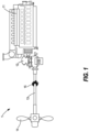
- the MPS 1 may be housed in, provide power to, and operatively propel a marine vessel, such as a container ship, tanker, passenger ship, fishing vessel, motor yacht, personal watercraft, or other vessel, where no limitation is intended herein.
- the MPS 1 may comprise an engine 11 or power unit, a transmission 12, a propeller shaft 13, a propeller 14, and, in some embodiments, a shaft brake 15.
- torque generated by the engine 11 may be transferred through the transmission 12 and the propeller shaft 13 to rotate the propeller 14, thereby driving the marine vessel through a body of water.
- the transmission 12 may control a direction of rotation of the propeller 14 by shifting into one of a Forward Gear (F), a Neutral Gear (N), or a Reverse Gear (R).
- F Forward Gear
- N Neutral Gear
- R Reverse Gear
- the MPS 1 may be operatively controlled by an operator 2 through one or more operator controls, including a throttle 21 and a gear shift 22 (not shown).
- the throttle 21 may operatively control the engine 11 and, more specifically, an Engine Speed (ES) of the engine 11.
- the gear shift 22 may operatively control the transmission 12 and, more specifically, a Current Gear (G) of the transmission 12.
- the MPS 1 may comprise two separate and independent sets of the engine 11, the transmission 12, the propeller shaft 13, the propeller 14, and, where applicable, the shaft brake 15, one of each located on a port side and a starboard side of the marine vessel.
- separate throttles 21 and gear shifts 22 may be configured to operatively control each side and set of the MPS 1.
- the MPS 1 may further comprise a Propulsion Control Processor (PCP) 16 (not shown), which operatively controls the engine 11, the transmission 12, and, where applicable, the shaft brake 15.
- the PCP 16 may further be programmed to enable, configure, activate, execute, and/or deactivate one or more Shift Protection Sequence(s) (SPS) during an operation of the marine vessel.
- the MPS 1 may further comprise an Engine Control Unit (ECU) 17 for operatively controlling the engine 11.
- the ECU 17 may be included in the PCP 16 and constitute the same component and, in other embodiments, the ECU 17 may constitute a separate component of the MPS 1.
- the role and scope of the PCP 16 and the ECU 17 may be better understood after a brief description of the following terms.
- the term "requested” may refer to any request inputted from the operator 2 through the throttle 21 or the gear shift 22.
- the operator 2 may input a Requested Engine Speed (RES) or a Requested Gear (RG) by altering a state of the throttle 21 and the gear shift 22, respectively.
- the state of the throttle 21 and/or the gear shift 22 are then communicated to the PCP 16.
- the PCP 16 may operatively communicate the RES to the engine 11 or the ECU 17, and/or the PCP 16 may operatively communicate the RG to the transmission 12.
- the PCP 16 may directly convert the RES and/or the RG into a Commanded Engine Speed (CES) and/or a Commanded Gear (CG), respectively, which may be in the form of a Pulse Wave Modulation (PWM) signal or related protocol known in the art.
- CES Commanded Engine Speed
- CG Commanded Gear
- PWM Pulse Wave Modulation
- the PCP 16 may determine that an SPS should be activated, for example, where an immediate gear reversal at the current ES could stall the engine 11.
- the PCP 16 may override the input from the operator 2 by activating and executing one of a plurality of enabled SPS. Once the SPS is deactivated, control of the throttle 21 and the gear shift 22 are once more returned to the operator 2.
- the term "commanded" may refer to any command communicated from the PCP 16 to the engine 11, the ECU 17, or to the transmission 12.
- the PCP 16 may communicate the CES or the CG to the engine 11 and to the transmission 12, respectively.
- the CES and/or the CG may be derived from the RES and/or the RG, or they may be derived from the shift protection logic of an active SPS.
- the CES and the CG may take the form of a PWM signal or related protocol known in the art.
- the term Engine Speed may refer to an "actual” or measured RPM of the engine 11, and may be distinguished from the RES or the CES.
- the term Current Gear (G) may refer to an "actual” gear of the transmission 12, and may be distinguished from the RG or the CG. It should be understood that, even if the CES is communicated to the engine 11 or the ECU 17, the ES may differ from the CES due to normal acceleration, deceleration, and/or variance of the engine 11. Likewise, it should be understood that, even if the CG is communicated to the transmission 12, the G may briefly differ from the CG due to normal shifting mechanisms, and mechanisms and/or protocols which are not discussed in the present disclosure.
- a method of programming one or more SPS which protect an engine 11 and a transmission 12 of a marine vessel during gear shifts is generally referred to be a reference numeral 200.
- the SPS may be programmed into the PCP 16 by a technician, an engineer, an operator 2, an Original Equipment Manufacturer (OEM), or similar personnel, where no limitation is intended herein.
- the one or more SPS may be enabled and tuned via the enablement and configuration of a plurality of SPS variables. Put in other terms, the enablement and configuration of the SPS variables by the technician may effectively dictate which SPS are enabled for the MPS 1; and may further dictate an activation logic, a deactivation logic, and/or a shift protection logic for each enabled SPS for the MPS 1.
- enablement and configuration of some SPS variables are required, while the enablement and configuration of other SPS variables are optional.
- enablement and configuration of the optional SPS variables may be at the discretion of the manufacturer, technician, engineer, operator 2, the OEM, customer, etc.
- the method may comprise first configuring a Shift Protection Type (SPT) to be a Basic Shift Protection (BSP) or an Advanced Shift Protection (ASP) (block 201).
- SPT Shift Protection Type
- BSP Basic Shift Protection
- ASP Advanced Shift Protection
- a plurality of SPS are enabled by the PCP 16 according to the SPT.
- SPT is configured to be the BSP, by default, a Normal Shift Protection (NSP) and a Basic Crash Reversal (BCR) are enabled.
- NSP Normal Shift Protection
- BCR Basic Crash Reversal
- the SPS of the BSP are also enabled, including the NSP and the BCR.
- SVMSP Slow Vessel Mode Shift Protection
- ACR Advanced Crash Reversal
- the BSP includes only time-based SPS, i.e. SPS which execute time-based shift protection logic.
- the ASP may include both time-based SPS and operating-variable-based SPS, i.e. SPS which execute both time-based and operating-variable-based shift protection logic.
- the ASP may include different time-based parameters compared to its BSP counterparts.
- the operating-variable-based shift protection logic of the ASP may execute quicker than the time-based shift protection logic of its BSP counterparts.
- the MPS 1 of the present disclosure may incorporate a modular shift protection logic including both simple, time-based SPS and complex, operating-variable based SPS in the same package.
- configuration of the required SPS variables may further include: configuring a Maximum Engine Speed to Shift (MESTS); configuring a Shift Protection Engine Speed Limit (SPESL); configuring a Shift Protection Hold Time (SPHT); configuring an Acceleration Time (AT); configuring a Deceleration Time (DT); and configuring a Neutral Hold Time (NHT), each of which will be described in greater detail below.
- MESTS Maximum Engine Speed to Shift
- SPESL Shift Protection Engine Speed Limit
- SPHT Shift Protection Hold Time
- AT Acceleration Time
- DT Deceleration Time
- NHT Neutral Hold Time
- the MESTS defines the maximum ES above which no gear shifts are allowed. In some embodiments, the ES must be at least 50 RPM below the MESTS for the PCP 16 to shift the transmission 12.
- the MESTS applies to all Shift Requests (SR), including Directional Shift Requests (DSR), Shift into Neutral Requests (SINR), and Shift Out of Neutral Requests (SONR). If a DSR is received while the ES exceeds the MESTS, then the CES is set to a Low Idle Engine Speed (LI) and the CG is held in the G until the ES decreases to at least 50 RPM below the MESTS.
- SR Shift Requests
- LI Low Idle Engine Speed
- a DSR is defined as a SR from the F to the R or vice versa.
- a SINR is defined as a SR from the F to the N or from the R to the N.
- a SONR is defined as a SR from the N to the F or from the N to the R.
- the LI refers to a preset RPM parameter of the engine 11 and/or the ECU 17, which may be set according to known standards within the art and/or according to specific applicational requirements.
- the SPESL defines the default CES for any active SPS until a throttle control is returned to the operator.
- the SPESL is always the CES if the active SPS is the NSP.
- the SPESL may instead define an artificial ceiling for the CES instead of setting the CES during the active SPS.
- the SPHT defines a period of time the CES is held at the SPESL during a Shift into Gear Phase (SIG-phase), which will be described in greater detail further in the specification.
- a Shift Protection Hold Time Counter (SPHTC) associated with the SPHT begins to count down as soon as any SPS enters the SIG-phase.
- the AT defines a period of time required for the marine vessel to reach top speed from zero km/h while a PORT / STBD Requested Throttle Position (PSRTP) is set to 100%.
- PSRTP PORT / STBD Requested Throttle Position
- the AT is determined during sea trials in accordance with Sea Trials and Transmission requirements.
- the PSRTP comprises the current RES(s) and the current RG(s) based on a state of the throttle(s) 21 and the gear shift(s) 22.
- the MPS 1 comprises only one set of the engine 11, transmission 12, throttle 21, and gear shift 22, the PSRTP may, contrary to the name, define the state of the single throttle 21 and gear shift 22.
- the MPS 1 comprises two independent sets of engines 11, transmissions 12, throttles 21, and gear shifts 22, e.g. one located on each of a port side and a starboard side of the marine vessel, the PSRTP may, in line with the name, define the state of both throttles 21 and gear shifts 22.
- the DT defines a period of time required for the ES to reduce to [LI + 100] RPM after the PSRTP is changed from 100% to 0% while the vessel is traveling at top speed.
- the DT is determined during sea trials in accordance with Sea Trials and Transmission requirements.
- the NHT defines a period of time the CG is held in N during a Neutral Hold Phase (NH-phase), which will be described in greater detail further in the specification.
- a Neutral Hold Time Counter (NHTC) associated with the NHT begins to count down as soon as any SPS enters the NH-phase.
- the method of programming one or more SPS variables further comprises enabling and configuring a plurality of optional SPS variables associated with improving an activation logic, a deactivation logic, and/or an efficiency of the BCR or the ACR (block 203). While the variables in block 202 are required for any SPS, the following variables are optional, but their enablement and configuration may improve an SPS efficiency during crash reversal operations.
- configuration of the required SPS variables may further include at least one of: enabling and configuring a Crash Reversal Engine Speed Limit (CRESL); enabling and configuring a Crash Reversal Enable / Disable Engine Speed (CREDES); enabling and configuring a Crash Reversal Enable Delay Time (CREDT); and/or enabling and configuring Crash Reversal Disable Delay Time (CRDDT), each of which will be described in greater detail below.
- CRESL Crash Reversal Engine Speed Limit
- CREDES Crash Reversal Enable / Disable Engine Speed
- CREDT Crash Reversal Enable Delay Time
- CCDDT Crash Reversal Disable Delay Time
- the CRESL defines, if enabled, a different default CES if the BCR or the ACR is the active SPS until a throttle control is returned to the operator. If the CRESL is disabled, the SPESL is the default CES if the BCR or the ACR is the active SPS. In some embodiments, the CRESL may instead define an artificial ceiling for the CES instead of setting the CES.
- the CREDES partially defines if/when the BCR or the ACR is the active SPS in conjunction with the CREDT and the CRDDT.
- the BCR or the ACR is the active SPS if the ES exceeds the CREDES for longer than the CREDT.
- the BCR or the ACR is deactivated if the ES is less than the CREDES for longer than the CRDDT.
- the CREDES is disabled, the BCR or the ACR is the active SPS if a Calculated Deceleration Time (CDT) exceeds, by a multiple, the DT.
- the CDT must exceed at least 20% of the DT.
- the CREDT partially defines if/when the BCR or the ACR is the active SPS in conjunction with the CREDES.
- the BCR or the ACR is the active SPS if the ES exceeds the CREDES for longer than the CREDT. If the CREDT is disabled, the BCR or the ACR is the active SPS if the ES exceeds the CREDES.
- the CRDDT partially defines if/when the BCR or the ACR is the active SPS in conjunction with the CREDES.
- the BCR or the ACR is deactivated if the ES is less than the CREDES for longer than the CRDDT. If the CRDDT is disabled, the BCR or the ACR is deactivated if the ES is less than the CREDES.
- the CDT defines an estimated period of time required for the marine vessel to fully decelerate.
- a Calculated Deceleration Time Counter (CDTC) associated with the CDT may begin to count down as soon as the any SPS enters a Shift Request Phase (SR-phase), which will be discussed in greater detail further below.
- SR-phase Shift Request Phase
- a High Idle Engine Speed is a preset RPM parameter of the engine 11 and/or the ECU 17.
- the HI may be set according to known standards within the art and/or according to specific applicational requirements.
- a Slow Vessel Mode Set Speed is a preset RPM parameter of the engine 11 and/or the ECU 17.
- the SVMSS may be set according to known standards within the art and/or according to specific applicational requirements.
- an Actual Acceleration Time defines a period of time that the ES has exceeded the SVMSS while the transmission 12 is in the F or the R.
- an Average Engine Speed defines the average ES over the last [AT] seconds.
- the method of programming one or more SPS further comprises enabling and configuring a plurality of optional SPS variables associated with improving an operating-variable-based shift protection logic of the BCR or the ACR (block 204). Similar to the variables in block 203, the following variables are optional, but their enablement and configuration may improve an SPS efficiency during various crash reversal operations. Moreover, in some embodiments, enablement and configuration of the following, optional SPS variables may be required to enable - and effectively constitute the enablement of - one or more optional SPS.
- block 204 may further include at least one of: enabling and configuring an Advanced Crash Reversal Shift Out of Gear Time (ACRSOGT); enabling and configuring an Advanced Crash Reversal Shift into Neutral Time (ACRSTNT); and/or enabling and configuring a Transmission Disengaged Pressure Limit (TDPL), each of which will be described in greater detail below.
- ACRSOGT Advanced Crash Reversal Shift Out of Gear Time
- ACRSTNT Advanced Crash Reversal Shift into Neutral Time
- TDPL Transmission Disengaged Pressure Limit
- the ACRSOGT partially defines if/when the ACR is activated in conjunction with the ACRSTNT and the TDPL. More specifically, in some embodiments, the ACRSOGT, the ACRSTNT, and the TDPL must all be enabled for the ACR to activate.
- the ACRSOGT further partially defines a period of time the CG is held in the RG during a Shift Out of Gear Phase (SOG-phase), which will be described in greater detail below.
- SOG-phase Shift Out of Gear Phase
- An Advanced Crash Reversal Shift Out of Gear Time Counter (ACRSOGTC) associated with the ACRSOGT begins to count down as soon as the ACR enters the SOG-phase.
- ACRSOGTC Advanced Crash Reversal Shift Out of Gear Time Counter
- the ACRSTNT partially defines if/when the ACR is activated in conjunction with the ACRSOGT and the TDPL. More specifically, in some embodiments, the ACRSOGT, the ACRSTNT, and the TDPL must all be enabled for the ACR to activate.
- the ACRSTNT further partially defines a period of time the CG is held in the N during the NH-phase.
- An Advanced Crash Reversal Shift to Neutral Time Counter (ACRSTNTC) associated with the ACRSTNT begins to count down as soon as the ACR enters the NH-phase.
- ACRSTNTC Advanced Crash Reversal Shift to Neutral Time Counter
- the TDPL partially defines if/when the ACR is activated in conjunction with the ACRSOGT and the ACRSTNT. More specifically, in some embodiments, the ACRSOGT, the ACRSTNT, and the TDPL must all be enabled for the ACR to activate. The TDPL further partially defines a period of time the CG is held in the RG during the SOG-phase. If the TDPL is enabled, the ACR exits the SOG-phase if a Transmission Oil Pressure (TOP) reduces to below the TDPL.
- TOP Transmission Oil Pressure
- a Crank Terminate Speed is a non-configurable parameter defining a threshold ES below which the engine 11 is considered stalled.
- the CTS may define a threshold ES above which the engine 11 is considered started.
- the CT may be set according to known standards within the art and/or according to specific applicational requirements.
- the ACR exits the SOG-phase if the ES reduces to below a multiple of the CTS. And in yet another embodiment, the ES must reduce to below 120% of the CTS.
- the method of programming one or more SPS further comprises enabling and configuring a plurality of optional SPS variables associated with improving an activation logic, a deactivation logic, and/or an efficiency of the SVMSP (block 205).
- the SVMSP and its associated SPS variables provide alternative CES parameters and timing parameters to improve the shift protection logic associated with a Slow Vessel Mode (SVM).
- SVM is an operating mode of the MPS 1 intended for docking operations, tight vessel maneuvers, operations in no-wake zones, and/or similar circumstances wherein the LI is reduced.
- enablement and configuration of the following, optional SPS variables may be required to enable - and effectively constitute the enablement of - one or more optional SPS.
- block 205 may further include at least one of: enabling and configuring a Slow Vessel Mode Shift protection engine speed limit (SVMSPESL); enabling and configuring a Slow Vessel Mode Shift Protection Enable / Disable Engine Speed (SVMSPEDES); enabling and configuring a Slow Vessel Mode Shift Protection Enable Time (SVMSPET); enabling and configuring a Slow Vessel Mode Shift Protection Disable Time (SVMSPDT); and/or enabling and configuring a Slow Vessel Mode Shift Protection Hold Time (SVMSPHT), each of which will be described in greater detail below.
- SVMSPESL Slow Vessel Mode Shift protection engine speed limit
- SVMSPEDES Slow Vessel Mode Shift Protection Enable / Disable Engine Speed
- SVMSPET Slow Vessel Mode Shift Protection Enable Time
- SVMSPDT Slow Vessel Mode Shift Protection Disable Time
- SVMSPHT Slow Vessel Mode Shift Protection Hold Time
- the SVMSPESL defines, if enabled, a different default CES if the SVMSP is the active SPS until a throttle control is returned to the operator. If the SVMSPESL is disabled, the SPESL is the default CES if the active SPS is the SVMSP. In some embodiments, the SVMSPESL may instead define an artificial ceiling for the CES instead of setting the CES.
- the SVMSPEDES partially defines if/when the SVMSP is the active SPS in conjunction with the SVMSPET and the SVMSPDT. In an embodiment, if the SVMSPEDES is enabled, the SVMSP is the active SPS when the ES is less than the SVMSPEDES for longer than the SVMSPET. Moreover, if the SVMSPEDES is enabled, the SVMSP is deactivated when the ES exceeds the SVMSPEDES for longer than the SVMSPDT.
- the SVMSPET partially defines if/when the SVMSP is the active SPS in conjunction with the SVMSPEDES. In an embodiment, if the SVMSPET is enabled, the SVMSP is the active SPS when the ES is less than the SVMSPEDES for longer than the SVMSPET. If the SVMSPET is disabled, the SVMSP is the active SPS when the ES is less than the CREDES.
- the SVMSPDT partially defines if/when the SVMSP is the active SPS in conjunction with the SVMSPEDES. In an embodiment, if the SVMSPDT is enabled, the SVMSP is deactivated if the ES exceeds the SVMSPEDES for longer than the SVMSPDT. If the SVMSPDT is disabled, the SVMSP is deactivated if the ES exceeds the SVMSPEDES.
- the SVMSPHT defines a period of time the CES is held at the SVMSPESL during the SIG-phase.
- the SVMSPHT if the SVMSPHT is enabled, it is used in place of the SPHT if the SVMSP is the active SPS. If the SVMSPHT is disabled, the SPHT is used even if the SVMSP is the active SPS.
- a Slow Vessel Mode Shift Protection Hold Time Counter (SVMSPHTC) associated with the SVMSPHT begins to count down as soon as the SVMSP enters the SIG-phase.
- SVMSPHTC Slow Vessel Mode Shift Protection Hold Time Counter
- the method of programming one or more SPS further comprises enabling and configuring a plurality of optional SPS variables associated with improving an operating-variable-based shift protection logic of any SPS (block 206). Similar to the variables in block 203, block 204, and block 205, the following variables are optional, but their enablement and configuration may improve an SPS efficiency during any SPS operation, including the BCR, the ACR, the NSP, and the SVMSP.
- enablement and configuration of the optional SPS variables may further include at least one of: enabling and configuring a Crash Reversal Exit Engine Speed (CREES); enabling and configuring an Advanced Crash Reversal Shift Into Gear Time (ACRSIGT); and/or enabling and configuring a Transmission Engaged Pressure Limit (TEPL), each of which will be described in greater detail below.
- Crash Reversal Exit Engine Speed Crash Reversal Exit Engine Speed
- ACRSIGT Advanced Crash Reversal Shift Into Gear Time
- TEPL Transmission Engaged Pressure Limit
- the CREES partially defines if/when any active SPS may exit the SIG-phase in conjunction with the ACRSIGT and the TEPL.
- the active SPS may exit the SIG-phase if the ES exceeds the CREES, and if the TOP exceeds the TEPL or an Advanced Crash Reversal Shift Into Gear Time Counter (ACRSIGTC) elapses.
- ACRSIGTC Advanced Crash Reversal Shift Into Gear Time Counter
- the ACRSIGT partially defines if/when any active SPS may exit the SIG-phase in conjunction with the CREES and the TEPL.
- the SPS exits the SIG-phase if the ES exceeds the CREES and the TOP exceeds the TEPL.
- the ACRSIGTC is associated with the ACRSIGT and begins to count down as soon as the active SPS enters the SIG-phase.
- the TEPL partially defines if/when any active SPS may exit the SIG-phase in conjunction with the CREES and the ACRSIGT.
- the SPS exits the SIG-phase if the ES exceeds the CREES and the ACRSIGTC elapses.
- the method of programming one or more SPS further comprises enabling and configuring a plurality of optional SPS variables associated with the shaft brake 15 (block 207).
- the following variables must be enabled and configured to utilize the shaft brake 15 during an active SPS.
- the following variables must be enabled and configured to utilize the shaft brake 15 when there is no active SPS, which will be further discussed below.
- enablement and configuration of the optional SPS variables may further include: enabling and configuring a Shaft Brake Engage Time (SBET); enabling and configuring a Shaft Brake Engagement Method (SBEM); and enabling and configuring a Shaft Brake Neutral Engage Status (SBNE), each of which will be described in greater detail below.
- SBET Shaft Brake Engage Time
- SBEM Shaft Brake Engagement Method
- SBNE Shaft Brake Neutral Engage Status
- the SBET defines a period of time the shaft brake 15 is engaged during the BCR.
- the shaft brake 15 may be engaged once the BCR is activated and disengage once the SBET elapses. In some embodiments, if the SBET is disabled, the shaft brake 15 may never be engaged during the BCR.
- the SBEM defines an aspect of the shift protection logic for the shaft brake 15. If the SBEM is configured as Brake with Timer (BWT), the shaft brake 15 may be engaged once the BCR is activated and disengaged once the SBET elapses. If the SBEM is configured as Brake During Directional Shift (BDDR), the shaft brake 15 may be engaged once the BCR is activated and disengaged once the BCR is deactivated and the throttle control is returned to the operator 2.
- BWT Brake with Timer
- BDDR Directional Shift
- the SBNE defines another aspect of the engagement logic for the shaft brake 15. If the SBNE is enabled, the shaft brake 15 may be engaged any time the CG is set to the N.
- each of the required SPS variables and the optional SPS variables which may be programmed by a technician into the PCP 16. Their enablement and configuration may effectively determine which SPS are enabled, if/when each SPS is activated and/or deactivated, and the particular shift protection logic therein.
- a method of protecting an engine and a transmission of a marine vessel during gear shifts is generally referred to by a reference numeral 300.
- the method may comprise receiving a SR (301); and activating an SPS from among the plurality of enabled SPS (302).
- the plurality of enabled SPS always includes the SPS of the BSP, including the NSP and the BCR, which execute time-based shift protection logic.
- the plurality of enabled SPS optionally includes the SPS of the ASP, including the SVMSP and the ACR, which execute alternate time-based and operating-variable-based shift protection logic.
- Enablement and configuration of the SPS of the ASP and the optional SPS variables therein may be at the discretion of the technician, operator 2, manufacturer, customer, or other relevant party.
- the ACR may provide alternate time-based parameters compared to its BSP counterparts. It may further utilize operating-variable-based shift protection logic to execute faster than the BCR in identical crash reversal scenarios.
- the SVMSP may provide alternative CES parameters and timing parameters if the MPS 1 is in the SVM.
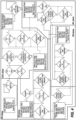
- FIG. 4 depicts the shift protection logic for each of the NSP, the BCR, the SVMSP, and the ACR.
- the logic of the BSP which includes at least the NSP and the BCR, is shown by solid arrows.
- the ASP which includes the NSP, the BCR, the SVMSP, and the ACR, is shown by both solid arrows and dotted arrows.
- the ASP may include all of the SPS of the BSP.
- some, but not necessarily all, of the SPS of the ASP may be incrementally and manually enabled and added to the BSP.
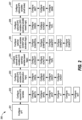
- FIG. 5 depicts a similar flowchart for the logic of the BSP only, including the NSP and the BCR. It may be noted that all of and only the events of FIG. 4 connected by solid arrows are depicted in FIG. 5 .
- All SPS may include four phases. However, some SPS may skip certain phases and each SPS may spend varying periods of time in each phase.
- a SR is received, which may be a DSR, a SINR, or a SONR.
- CG is shifted into the RG or the CG is held in the G while the vessel decelerates. If the active SPS is the NSP or the SVMSP, this phase is skipped. If the active SPS is the ACR, the CG is shifted into the RG during the SOG-phase. If the SPS is the BCR, the CG is held in the G during the SOG-phase.
- SOG-phase Shift Out of Gear Phase
- a Neutral Hold Phase (NH-phase) the CG is shifted into and held in the N. If the SPS is the NSP or the SVMSP, this phase is skipped. If the SPS is the BCR or the ACR, this phase is executed. In some embodiments, the NH-phase is generally shorter for the BCR than the ACR.
- SIG-phase Shift into Gear Phase
- the CG is shifted into and held in the RG.
- SPS is the NSP or the SVMSP
- the prior two phases have been skipped and the SPS begins at the SIG-phase immediately.
- the SPS is the BCR or the ACR
- the SPS enters the SIG-phase upon completion of the NH-phase.
- the BCR and the ACR may behave identically to the NSP if the relevant SPS variables are the same.
- the BCR is the default time-based SPS that is employed to prevent directional shifts while the marine vessel is moving fast enough to stall the engine.
- the BCR may always be enabled.
- the BCR includes four phases: the SR-phase, the SIG-phase, the NH-phase, and the SOG-phase.
- a SR is received, and specifically a DSR.
- no gear shifts are allowed unless the MESTS exceeds the ES by at least 50 RPM. If a DSR is received while the ES exceeds the MESTS, then the PCP 16 sets the CES to the LI and maintains the CG at the G until the ES decreases to at least 50 RPM below the MESTS.
- the PCP 16 may override the RES and RG when activating an SPS.
- the G is in F; the RG is in R; but the CG remains at F.
- the RES can be Any Speed (AS), the CES has been set to the LI.
- the SPS enters the SOG-phase.
- the BCR is activated if a simulated deceleration time exceeds, by a multiple, the DT.
- the simulated deceleration time is defined by the CDT.
- the CDT must exceed at least 20% of the DT to active the BCR.
- the BCR is the active SPS unless the ACRSOGT, the ACRSTNT, and the TDPL are all enabled, whereby the ACR becomes the active SPS.
- the BCR may also be activated if a Crash Reversal (CR) variable is enabled, wherein the CR is enabled only if a plurality of optional SPS variables associated with improving an activation logic, a deactivation logic, and/or an efficiency of the BCR or the ACR are enabled and configured.
- a Crash Reversal (CR) variable is enabled, wherein the CR is enabled only if a plurality of optional SPS variables associated with improving an activation logic, a deactivation logic, and/or an efficiency of the BCR or the ACR are enabled and configured.
- the CREDES and the CREDT are enabled, the CR is enabled if the ES exceeds the CREDES for longer than the CREDT. If the CREDES is enabled and the CREDT is disabled, the CR is enabled if the ES exceeds the CREDES.
- a different SPS such as the NSP or the SVMSP, or no SPS may be activated instead.
- the BCR is the active SPS, contrary to the name, during the SOG-phase, the CG is held in the G.
- the BCR completes the SOG-phase once the CDT becomes zero or once the CDTC elapses.
- the CDTC begins to count down as soon as the DSR is received, i.e. during the SR-phase, regardless of whether or not the ES is at least 50 RPM below the MESTS.
- the BCR enters the NH-phase, wherein the CG is shifted into and held in the N.
- the NH-phase is complete once the NHTC elapses, which begins to count down as soon as the BCR enters the NH-phase.
- a Shift Out of Gear Neutral Hold (SOGNH) variable determines whether to utilize BCR timing parameters or ACR timing parameters during the NH-phase.
- SOGNH is disabled if the BCR is the active SPS. If the SOGNH is disabled, the NHTC may dictate a time-based shift protection logic during the NH-phase.
- the BCR enters the SIG-phase, wherein the CG is shifted into and held in the RG.
- the SIG-phase is complete once the SPHTC elapses, which begins to count down as soon as the BCR enters the SIG-phase.
- throttle and gear shift control are returned to the operator 2.
- the SIG-phase of the BCR and, indeed, any SPS may further benefit from enablement and configuration of a plurality of optional SPS variables associated with improving the operating-variable-based shift protection of any SPS.
- the SIG-phase is complete if the ES exceeds the CREES and the TOP exceeds the TEPL.
- the CREES and the ACRSIGT are enabled, the SIG-phase is complete if the ES exceeds the CREES and the ACRSIGTC elapses.
- the BCR may be deactivated. More specifically, in some embodiments, the BCR may further benefit from enablement and configuration of the plurality of optional SPS variables associated with improving the activation logic, the deactivation logic, and/or the efficiency of the BCR or the ACR. In some embodiments, if the CREDES and the CRDDT are enabled, the BCR is deactivated if the CREDES exceeds the ES for longer than the CRDDT. And in other embodiments, if the CREDES is enabled and the CRDDT is disabled, the BCR is deactivated if the ES reduces to below the CREDES.
- the shaft brake 15 may optionally be engaged during the BCR depending on the configuration and enablement of a plurality of optional SPS variables associated with the shaft brake 15. In the same or other embodiments, engagement of the shaft brake 15 may improve an efficiency of the BCR without employing additional operating-variable-based shift protection logic. It is worth noting that the shaft brake 15 may be engaged during the BCR, but never during the ACR.
- the shaft brake 15 may never be engaged during the BCR. If the SBET is enable and the SBEM is configured as BWT, the shaft brake 15 may be engaged once the BCR is activated and disengaged once the SBET elapses. If the SBET is enabled and the SBEM is configured as BDDS, the shaft brake 15 may be engaged once the BCR is activated and disengaged once the BCR is deactivated and the throttle control is returned to the operator 2.
- the SBNE criteria overrides control of the shaft brake 15. More specifically, if the SBNE is enabled, the shaft brake 15 may be engaged any time the CG is set to the N.
- the ACR is an optional SPS that is employed to prevent directional shifts while the marine vessel is moving fast enough to stall the engine. Moreover, the ACR may provide faster directional shifts than the BCR by employing alternate time-based and operating-variable based shift protection logic. As previously discussed, the ACR includes four phases: the SR-phase, the SIG-phase, the NH-phase, and the SOP-phase.
- a SR is received, and specifically a DSR.
- no gear shifts are allowed unless the MESTS exceeds the ES by at least 50 RPM. If a DSR is received while the ES exceeds the MESTS, then the PCP 16 sets the CES to the LI and maintains the CG at the G until the ES decreases to at least 50 RPM below the MESTS.
- the SPS enters the SOG-phase.
- the ACR may be activated if a simulated deceleration time exceeds, by a multiple, the DT.
- the simulated deceleration time is defined by the CDT.
- the CDT must exceed at least 20% of the DT.
- the ACR may also be activated if the CR is enabled. As previously discussed, if the CREDES and the CREDT are enabled, the CR is enabled if the ES exceeds the CREDES for longer than the CREDT. If the CREDES is enabled and the CREDT is disabled, the CR is enabled if the ES exceeds the CREDES. If the CR is disabled and the CDT fails to exceed the CDT by the required multiple, a different SPS, such as the NSP or the SVMSP, or no SPS may be activated instead.
- a different SPS such as the NSP or the SVMSP, or no SPS may be activated instead.
- the ACR is activated only if a plurality of optional SPS variables associated with improving an operating-variable-based shift protection logic of the BCR or the ACR are enabled and configured; and if a maximum period of time required to execute the BCR exceeds a maximum period of time required to execute the ACR.
- the ACR is activated only if the ACRSOGT, the ACRSIGT, and the TDPL are enabled. If one or more of the above are disabled, the BCR becomes the active SPS. And in other embodiments, if the sum of the ACRSOGT and the ACRSTNT exceeds the CDT, then a maximum time period required to perform the ACR may exceed that of the BCR, and the BCR becomes the active SPS.
- the CG is shifted into and held in the RG.
- the SOG-phase is complete if the ACRSOGT elapses, the TDPL exceeds the TOP, or the ES reduces to below a multiple of the CTS. In some embodiments, the ES must reduce to below 120% of the CTS.
- the ACR enters the NH-phase, wherein the CG is shifted into and held in the N.
- the SOGNH determines whether to utilize BCR timing parameters or ACR timing parameters during the NH-phase.
- the SOGNH is enabled if the ACR is the active SPS. If the SOGNH is enabled, the NH-phase is complete once any of the following conditions are satisfied. In an embodiment, the NH-phase is complete if the ACRSTNTC elapses.
- the ACR may further benefit from the enablement and configuration of a plurality of optional SPS variables associated improving an activation logic, a deactivation logic, and/or an efficiency of the BCR or the ACR. More specifically, in some embodiments, if the CRESL is enabled, the NH-phase is complete once the ES exceeds the CRESL.
- the ACR enters the SIG-phase, wherein the CG is shifted into and held in the RG.
- the SIG-phase is complete once the SPHTC elapses, which begins to count down as soon as the ACR enters the SIG-phase.
- throttle and gear shift control are returned to the operator 2.
- the SIG-phase of the ACR and, indeed, any SPS may further benefit from enablement and configuration of a plurality of optional SPS variables associated with improving the operating-variable-based shift protection of any SPS.
- the SIG-phase is complete if the ES exceeds the CREES and the TOP exceeds the TEPL.
- the CREES and the ACRSIGT are enabled, the SIG-phase is complete if the ES exceeds the CREES and the ACRSIGTC elapses.
- the ACR may be deactivated. Moreover, the ACR may further benefit from enablement and configuration of a plurality of optional SPS variables associated with improving the activation logic, the deactivation logic, and/or the efficiency of the BCR or the ACR. In some embodiments, if the CREDES and the CRDDT are enabled, the ACR is deactivated if the CREDES exceeds the ES for longer than the CRDDT. And in other embodiments, if the CREDES is enabled and the CRDDT is disabled, the ACR is deactivated if the CREDES exceeds the ES.
- the NSP is the default SPS that is activated any time the conditions for the BCR, the ACR, and the SVMSP are not met.
- the NSP may include the SR-phase, skip the SOG-phase and the NH-phase, and immediately enter the SIG-phase.
- a SR is received, which may be any SR and not necessarily a DSR.
- the MESTS exceeds the ES by at least 50 RPM.
- the PCP 16 sets the CES to the LI and maintains the CG at the G until the ES decreases to at least 50 RPM below the MESTS.
- the NSP immediately enters the SIG-phase, wherein the CG is shifted into and held in the RG.
- the SIG-phase is complete once the SPHTC elapses, which begins to count down as soon as the NSP enters the SIG-phase. Once the SIG-phase is complete, throttle and gear shift control are returned to the operator 2.
- the SIG-phase of the NSP and, indeed, any SPS may further benefit from enablement and configuration of a plurality of optional SPS variables associated with improving the operating-variable-based shift protection of any SPS.
- the SIG-phase is complete if the ES exceeds the CREES and the TOP exceeds the TEPL.
- the CREES and the ACRSIGT are enabled, the SIG-phase is complete if the ES exceeds the CREES and the ACRSIGTC elapses.
- the SVMSP is an optional SPS that provides alternative CES and timing parameters for low engine speed operations. It is the active SPS if the conditions for the BCR and the ACR are not met, and the conditions for the SVMSP are met. As previously discussed, the SVMSP may include the SR-phase, skip the SOG-phase and the NH-phase, and immediately enter the SIG-phase.
- a SR is received, which may be any SR and not necessarily a DSR.
- the MESTS exceeds the ES by at least 50 RPM.
- the PCP 16 sets the CES to the LI and maintains the CG at the G until the ES decreases to at least 50 RPM below the MESTS.
- the SVMSP may be activated only if a plurality of optional SPS variables associated with improving an activation logic, a deactivation logic, and/or an efficiency of the SVMSP are enabled and configured.
- the SVMSPET if the SVMSPET is enabled, the SVMSP is activated if the ES is less than the SVMSPEDES for longer than the SVMSPET. And in other embodiments, if the SVMSPET is disabled, the SVMSP is activated if the ES is less than the CREDES. If the SVMSP is not activated, a different SPS, such as the NSP, or no SPS may be activated instead.
- the SVMSP If the SVMSP is activated, the SVMSP immediately enters the SIG-phase, wherein the CG is shifted into and held in the RG.
- the SIG-phase is complete once the SVMSPHTC elapses, which begins to count down as soon as the SVMSP enters the SIG-phase. Once the SIG-phase is complete, throttle and gear shift control are returned to the operator 2.
- the SIG-phase of the SVMSP and, indeed, any SPS may further benefit from enablement and configuration of a plurality of optional SPS variables associated with improving the operating-variable-based shift protection of any SPS.
- the SIG-phase is complete if the ES exceeds the CREES and the TOP exceeds the TEPL.
- the CREES and the ACRSIGT are enabled, the SIG-phase is complete if the ES exceeds the CREES and the ACRSIGTC elapses.
- the SVMSP may be deactivated. Moreover, the SVMSP may further benefit from enablement and configuration of a plurality of optional SPS variables associated with improving an activation logic, a deactivation logic, and/or an efficiency of the SVMSP.
- the SVMSP if the SVMSPEDES and the SVMSPDT are enabled, the SVMSP is deactivated if the ES exceeds the SVMSPEDES for longer than the SVMSPDT. And in other embodiments, if the SVMSPDT is disabled, the SVMSP is deactivated if the ES exceeds the SVMSPEDES.
- the operator may enter a SINR while an SPS is active, including any of the BCR, the ACR, the NSP, and the SVMSP.
- the PCP 16 may immediately deactivate the active SPS.
- the active SPS is the BCR or the ACR and the active SPS is deactivated before the CDTC elapses
- the CDTC may continue to count down.
- the BCR or the ACR is deactivated by a SINR and the CDTC has yet to elapse
- the operator 2 once again requests the opposite gear
- the BCR is (re)activated, where the opposite gear refers to the original RG. It is worth noting that, even if the ACR was the original active SPS, if the above conditions are true, the BCR will be reactivated and not the ACR.
- SR which may be a DSR, a SINR, or a SONR.
- SLR Split Lever Request
- the SLR defines a PSRTP comprising an opposite starboard RG and port side RG, i.e. one in the F and the other in the R. If this is the case, the PCP 16 will not activate the ACR.
- a split lever PSRTP may effectively cause the CDT to reduce to zero, such that the activation conditions for the BCR and the ACR cannot be fulfilled and the NSP becomes the active SPS.
- a plurality of optional SPS variables associated with the shaft brake 15 must be enabled and configured to utilize the shaft brake 15 when there is no active SPS. Specifically, if the SBNE is enabled, the shaft brake 15 may be engaged any time the CG is set to the N. It is worth noting, however, that the shaft brake 15 will never be engaged when shifting out of the N.
- the modular shift protection algorithm of the present disclosure may be employed in any number of marine vessels, including but not limited to container ships, tankers, passenger ships, fishing vessels, motor yachts, personal watercraft, and yet other vessels, where no limitation is intended herein.
- the disclosed shift protection logic may be applied to marine vessels and marine propulsion systems comprising a single engine, transmission, and propeller; or marine vessels and marine propulsion systems comprising two or more independent sets of engines, transmissions, and propellers, e.g. one located on each of a port side and a starboard side.
- the disclosed shift protection logic may operatively control and utilize one or more shaft brakes to further improve the efficiency of the relevant SPS.
- the disclosed SPS may be programmed into and executed by a PCP interoperable with a number of mechanical systems, electrical systems, and communication protocols of the marine vessel.
- the plurality of SPS and the shift protection logic therein of the present disclosure include both simple, time-based shift protection logic and complex, operating-variable-based shift protection logic.
- the SPS of the ASP may further be modularized and incrementally implemented, such that a full spectrum of shift protection protocols is offered in a single package.
- the combination of enabled and/or configured SPS may be customized by the manufacturer, distributor, client, customer, etc., and may further be adjusted in the future by reprogramming the PCP without the need for hardware alterations.
- the disclosed shift protection algorithms may be employed during normal shifting operations, including directional shift requests, shifts into and out of neutral requests, and split lever requests; crash reversal operations; slow vessel mode operations; traditional troll mode operations; and yet other operating scenarios.
- multiple shift protection strategies may be combined into a single configurable system.
Landscapes
- Engineering & Computer Science (AREA)
- Mechanical Engineering (AREA)
- Chemical & Material Sciences (AREA)
- Combustion & Propulsion (AREA)
- Ocean & Marine Engineering (AREA)
- General Engineering & Computer Science (AREA)
- Control Of Transmission Device (AREA)
Claims (12)
- Verfahren zum Programmieren einer oder mehrerer Schaltschutzsequenzen (SPS, shift protection sequences), die einen Motor (11) und ein Getriebe (12) eines Wasserfahrzeugs bei Gangschaltvorgängen (200) schützen, wobei das Verfahren (200) die Schritte umfasst:
Konfigurieren eines Schaltschutztyps (SPT, shift protection type) als Basisschaltschutz (BSP, basic shift protection) oder als erweiterter Schaltschutz (ASP advanced shift protection) (201), wobei:
wenn der SPT als BSP konfiguriert ist, standardmäßig ein normaler Schaltschutz (NSP, normal shift protection) und eine Basis-Crash-Umkehrung BCR (basic crash reversal) freigegeben sind, wobei:im NSP die folgenden Phasen auftreten:eine Schaltanforderungsphase (SR-Phase, Shift Request Phase), in der eine Schaltanforderung (SR, shift request) empfangen wird; undeine Gangeinlegephase (SIG-Phase, shift into gear phase) unmittelbar nach der SR-Phase, in der ein Soll-Gang (CG, command gear) in den angeforderten Gang (RG, requested gear) eingelegt und in diesem gehalten wird; undin der BCR die folgenden Phasen auftreten:eine SR-Phase, in der eine Richtungsumkehranforderung (DSR, Directional Shift Request) empfangen wird, wobei eine DSR eine SR von Vorwärtsgang (F) nach Rückwärtsgang (R) oder von R nach F ist;eine Gangauslegephase (SOG-Phase, Shift Out of Gear Phase), in der der CG im aktuellen Gang (G) gehalten wird, während das Wasserfahrzeug verzögert;eine Leerlaufhaltephase (NH-Phase, Neutral Hold Phase), in der der CG nach Leerlauf (N) geschaltet und dort gehalten wird; undeine SIG-Phase nach Abschluss der NH-Phase, in der der CG nach RG geschaltet und dort gehalten wird; oderwenn der SPT als ASP konfiguriert ist, standardmäßig der NSP, die BCR, ein Schaltschutz bei Langsamfahrt (SVMSP, Slow Vessel Mode Shift Protection) und eine erweiterte Crash-Umkehrung (ACR, (advanced crash reversal) freigegeben sind, wobei:im SVMSP die folgenden Phasen auftreten:eine SR-Phase, in der eine Schaltanforderung (SR, Shift Request) empfangen wird; undeine SIG-Phase unmittelbar nach der SR-Phase, in der der CG nach RG geschaltet und dort gehalten wird; undin der ACR die folgenden Phasen auftreten:eine SR-Phase, in der ein DSR empfangen wird;eine SOG-Phase, in der der CG nach RG geschaltet und dort gehalten wird, wobei die SOG-Phase abgeschlossen ist, wenn:eine ACR-Gangauslegezeit (ACRSOGT, Advanced Crash Reversal Shift Out of Gear Time) verstrichen ist,ein Getriebeöldruck (TOP, Transmission Oil Pressure) unter den Getriebeausrückdruckgrenzwert (TDPL, Transmission Disengaged Pressure Limit) fällt odereine Motordrehzahl (ES, engine speed) unter ein Mehrfaches einer Kurbelwellenenddrehzahl (CTS, Crank Terminate Speed) fällt;eine NH-Phase, in der der CG nach N geschaltet und dort gehalten wird, wobei die NH-Phase abgeschlossen ist, wenn:
eine ACR-Leerlaufschaltzeit (ACRSTNT, Advanced Crash Reversal Shift to Neutral Time) verstrichen ist; oderdie ES eine Crash-Umkehr-Motordrehzahlgrenze (CRESL, Crash Reversal Engine Speed Limit) überschreitet; undeine SIG-Phase nach Abschluss der NH-Phase, in der der CG nach RG geschaltet und dort gehalten wird; undKonfigurieren einer Mehrzahl erforderlicher SPS-Variablen (20), einschließlich:Konfigurieren einer maximalen Motordrehzahl zum Schalten (MESTS, Maximum Engine Speed to Shift), wobeidie MESTS die maximale ES definiert, oberhalb derer kein Gangschalten erlaubt ist;Konfigurieren einer Schaltschutz-Motordrehzahlgrenze (SPESL, shift protection engine speed limit), wobei die SPESL die Standard-Solldrehzahl (CES, command engine speed) für jede aktive SPS bis zur Rückgabe der Drosselsteuerung an den Bediener definiert;Konfigurieren einer Schaltschutz-Haltezeit (SPHT, shift protection hold time), wobei die SPHT einen Zeitraum definiert, in dem die CES während der SIG-Phase auf der SPESL gehalten wird;Konfigurieren einer Beschleunigungszeit (AT, acceleration time), wobei die AT einen Zeitraum definiert, den das Wasserfahrzeug benötigt, um von null Knoten auf Höchstgeschwindigkeit zu kommen, während eine angeforderte Steuerbord-Backbord-Drosselposition (PSRTP, PORT/STBD Requested Throttle Position) auf 100 % eingestellt ist;Konfigurieren einer Verzögerungszeit (DT, deceleration time), wobei die DT eine Zeitspanne definiert, die erforderlich ist, damit die Motordrehzahl (ES) auf [niedrige Leerlaufdrehzahl (LI) + 100] U/min reduziert wird, nachdem die angeforderte Steuerbord-Backbord-Drosselposition (PSRTP, PORT/STBD Requested Throttle Position) von 100 % auf 0 % geändert wurde, während das Wasserfahrzeug mit Höchstgeschwindigkeit fährt; undKonfigurieren einer Leerlaufhaltezeit (NHT, neutral hold time), wobei die NHT einen Zeitraum definiert, in dem der CG während der NH-Phase in N gehalten wird;wobei die Standard-SPS des ASP schrittweise freigebbar und zum BSP hinzufügbar ist; und wobei die Standard-SPS des ASP schrittweise sperrbar und aus dem ASP entfernbar ist. - Verfahren (200) nach Anspruch 1, das ferner den Schritt des Freigebens und Konfigurierens einer Mehrzahl optionaler SPS-Variablen umfasst, die der Verbesserung einer Aktivierungslogik, einer Deaktivierungslogik und/oder einer Effizienz des BCR oder des ACR (203) zugeordnet sind, einschließlich mindestens eines der folgenden Schritte:Freigeben und Konfigurieren der CRESL;Freigeben und Konfigurieren einer Motordrehzahl zum Freigeben/ Sperren der Crash-Umkehrung (CREDES, crash reversal enable/disable engine speed);Freigeben und Konfigurieren einer Verzögerungszeit für die Freigabe der Crash-Umkehr (CREDT, crash reversal enable delay time); und/oderFreigeben und Konfigurieren einer Verzögerungszeit für die Sperrung der Crash-Umkehr (CRDDT, crash reversal disable delay time), wobei CREDES in Verbindung mit CREDT und CRDDT teilweise definiert, ob/wann BCR oder ACR die aktive SPS ist.
- Verfahren (200) nach Anspruch 1, das ferner den Schritt des Freigebens und Konfigurierens einer Mehrzahl optionaler SPS-Variablen umfasst, die der Verbesserung einer betriebsvariablenbasierten Schaltschutzlogik des BCR oder des ACR (204) zugeordnet sind, einschließlich mindestens eines der folgenden Schritte:Freigeben und Konfigurieren der ACRSOGT;Freigeben und Konfigurieren der ACRSTNT; und/oderFreigeben und Konfigurieren des TDPL.
- Verfahren (200) nach Anspruch 1, das ferner den Schritt des Freigebens und Konfigurierens einer Mehrzahl optionaler SPS-Variablen umfasst, die der Verbesserung einer Aktivierungslogik, einer Deaktivierungslogik und/oder einer Effizienz des SVMSP (205) zugeordnet sind, einschließlich mindestens eines der folgenden Schritte:Freigeben und Konfigurieren eines Motordrehzahlgrenzwerts für den Schaltschutz bei Langsamfahrt (SVMSPESL, slow vessel mode shift protection engine speed limit), wobei der SVMSPESL einen Standard-CES definiert, wenn der SVMSP die aktive SPS ist;Freigeben und Konfigurieren einer Motordrehzahl zum Freigeben/ Sperren des Schaltschutzes bei Langsamfahrt (SVMSPEDES, slow vessel mode shift protection enable/disable engine speed);Freigeben und Konfigurieren einer Freigabezeit für den Schaltschutz bei Langsamfahrt (SVMSPET, slow vessel mode shift protection enable time);Freigeben und Konfigurieren einer Sperrzeit für den Schaltschutz bei Langsamfahrt (SVMSPDT, slow vessel mode shift protection disable time), wobei SVMSPEDES in Verbindung mit SVMSPET und SVMSPDT teilweise definiert, ob/wann SVMSP die aktive SPS ist;
und/oderFreigeben und Konfigurieren einer Haltezeit für den Schaltschutz bei Langsamfahrt (SVMSPHT, slow vessel mode shift protection hold time), wobei die SVMSPHT eine Zeitspanne definiert, in der die CES während der SIG-Phase auf der SVMSPESL gehalten wird. - Verfahren (200) gemäß Anspruch 4, bei dem der SVMSPzum Bereitstellen alternativer CES- und Zeitparameter für den Betrieb bei niedriger Motordrehzahl dient; unddie aktive SPS ist, wenn die Motordrehzahl (ES) länger als die SVMSPET niedriger als der SVMSPEDES ist,wobei im SVMSP:die SIG-Phase abgeschlossen ist, sobald ein SVMSPHT-Zähler (SVMSPHTC, Slow Vessel Mode Shift Protection Hold Time Counter) abgelaufen ist, der zu zählen beginnt, sobald der SVMSP in die SIG-Phase eintritt; undsobald die SIG-Phase abgeschlossen ist, die Kontrolle über Drossel und Gangschaltung an den Bediener zurückgegeben wird.
- Verfahren (200) nach Anspruch 1, das ferner den Schritt des Freigebens und Konfigurierens einer Mehrzahl optionaler SPS-Variablen umfasst, die der Verbesserung einer betriebsvariablenbasierten Schaltschutzlogik einer beliebigen SPS (206) zugeordnet sind, einschließlich mindestens eines der folgenden Schritte:Freigeben und Konfigurieren einer Crash-Umkehrungsabbruch-Motordrehzahl (CREES, crash reversal exit engine speed);Freigeben und Konfigurieren einer ACR-Gangeinlegezeit (ACRSIGT, advanced crash reversal shift into gear time); und/oderFreigeben und Konfigurieren eines Druckgrenzwerts bei Getriebeeingriff (TEPL, transmission engaged pressure limit), wobei die CREES in Verbindung mit der ACRSIGT und der TEPL teilweise definiert, ob/wann eine aktive SPS die SIG-Phase verlassen kann.
- Verfahren (200) nach Anspruch 1, bei dem die BCR:eine zeitbasiertes SPS zum Verhindern von Richtungsumkehrungen ist, während das Wasserfahrzeug schnell genug fährt, um den Motor abzuwürgen (11); undaktiviert wird, wenn eine berechnete Verzögerungszeit (CDT, Calculated Deceleration Time) die DT um ein Mehrfaches überschreitet, wobei:
die CDT einen geschätzten Zeitraum definiert, der zum vollständigen Verzögern des Wasserfahrzeugs erforderlich ist; undwobei in der BCR:die SOG-Phase abgeschlossen ist, sobald die CDT null wird oder sobald ein CDT-Zähler (CDTC, Calculated Deceleration Time Counter) abgelaufen ist, der zu zählen beginnt, sobald die DSR empfangen wird;die NH-Phase abgeschlossen ist, sobald ein NHT-Zähler (NHTC, Neutral Hold Time Counter) abgelaufen ist, der zu zählen beginnt, sobald die BCR in die NH-Phase eintritt;die SIG-Phase abgeschlossen ist, sobald ein SPHT-Zähler (SPHTC, Shift Protection Hold Time Counter) abgelaufen ist, der zu zählen beginnt, sobald die BCR in die SIG-Phase eintritt; undsobald die SIG-Phase abgeschlossen ist, die Kontrolle über Drossel und Gangschaltung an den Bediener zurückgegeben wird. - Verfahren zum Schutz eines Motors und eines Getriebes eines Wasserfahrzeugs während des Gangwechsels (300), wobei das Verfahren (300) die folgenden Schritte umfasst:Empfangen einer Schaltanforderung (SR, shift request) (301); undAktivieren einer Schaltschutzsequenz (SPS, shift protection sequence) aus einer Mehrzahl von freigegebenen SPS (302);wobei die Mehrzahl von freigegebenen SPS immer einen normalen Schaltschutz (NSP, normal shift protection) und eine Basis-Crash-Umkehrung (BCR, basic crash reversal) umfasst, die eine zeitbasierte Schaltschutzlogik ausführen, wobei:im NSP die folgenden Phasen auftreten:eine Schaltanforderungsphase (SR-Phase, Shift Request Phase), in der eine Schaltanforderung (SR, shift request) empfangen wird; undeine Gangeinlegephase (SIG-Phase, shift into gear phase) unmittelbar nach der SR-Phase, in der ein Soll-Gang (CG, command gear) in den angeforderten Gang (RG, requested gear) eingelegt und in diesem gehalten wird; undin der BCR die folgenden Phasen auftreten:eine SR-Phase, in der eine Richtungsumkehranforderung (DSR, Directional Shift Request) empfangen wird, wobei eine DSR eine SR von Vorwärtsgang (F) nach Rückwärtsgang (R) oder von R nach F ist;eine Gangauslegephase (SOG-Phase, Shift Out of Gear Phase), in der der CG im aktuellen Gang (G) gehalten wird, während das Wasserfahrzeug verzögert;eine Leerlaufhaltephase (NH-Phase, Neutral Hold Phase), in der der CG nach N (Leerlauf) geschaltet und dort gehalten wird; undeine SIG-Phase nach Abschluss der NH-Phase, in der der CG nach RG geschaltet und dort gehalten wird;wobei die Mehrzahl von freigegebenen SPS optional einen Schaltschutz bei Langsamfahrt (SVMSP, Slow Vessel Mode Shift Protection) und eine erweiterte Crash-Umkehrung (ACR, advanced crash reversal) umfasst, die eine abwechselnde zeitbasierte und betriebsvariablenbasierte Schaltschutzlogik ausführen, wobei:im SVMSP die folgenden Phasen auftreten:eine SR-Phase, in der eine Schaltanforderung (SR, Shift Request) empfangen wird; undeine SIG-Phase unmittelbar nach der SR-Phase, in der der CG in den RG geschaltet und dort gehalten wird; undin der ACR die folgenden Phasen auftreten:eine SR-Phase, in der ein DSR empfangen wird;eine SOG-Phase, in der der CG in den RG geschaltet und dort gehalten wird, wobei die SOG-Phase abgeschlossen ist, wenn:eine ACR-Gangauslegezeit (ACRSOGT, Advanced Crash Reversal Shift Out of Gear Time) verstrichen ist,ein Getriebeöldruck (TOP, Transmission Oil Pressure) unter den Getriebeausrückdruckgrenzwert (TDPL, Transmission Disengaged Pressure Limit) fällt odereine Motordrehzahl (ES, engine speed) unter ein Mehrfaches einer Kurbelwellenenddrehzahl (CTS, Crank Terminate Speed) fällt;eine Leerlaufhaltephase (NH-Phase, Neutral Hold Phase), in der der CG nach N geschaltet und dort gehalten wird, wobei die NH-Phase abgeschlossen ist, wenn:eine ACR-Leerlaufschaltzeit (ACRSTNT, Advanced Crash Reversal Shift to Neutral Time) verstrichen ist; oderdie ES einen Crash-Umkehr-Motordrehzahlgrenzwert (CRESL, Crash Reversal Engine Speed Limit) überschreitet; undeine SIG-Phase nach Abschluss der NH-Phase, in der der CG nach RG geschaltet und dort gehalten wird.
- Verfahren (300) gemäß Anspruch 8, bei dem der Schritt des Empfangens des SR (301) das Empfangen einer Richtungsumkehranforderung (DSR) umfasst;
wobei die aus der Mehrzahl freigegebener SPS aktivierte SPS die BCR ist, wenn:eine simulierte Verzögerungszeit eine Verzögerungszeit (DT, deceleration time) um ein Mehrfaches überschreitet;wobei das Aktivieren der BCR ferner das Ausführen der folgenden zeitbasierten Schaltschutzlogik umfasst:Halten des Getriebes (12) in einem aktuellen Gang (G);Schalten des Getriebes (12) in Leerlauf (N);Halten des Getriebes (12) in N;Schalten des Getriebes (12) in einen angeforderten Gang (RG);Halten des Getriebes (12) in RG; undZurückgeben einer Drosselsteuerung an einen Bediener (2). - Verfahren (300) nach Anspruch 9, bei dem die aus der Mehrzahl freigegebener SPS aktivierte SPS nur dann die ACR ist, wenn:eine Mehrzahl optionaler SPS-Variablen, die der Verbesserung einer betriebsvariablenbasierten Schaltschutzlogik der BCR oder der ACR zugeordnet sind, freigegeben und konfiguriert sind; undeine maximale Zeitdauer, die zur Ausführung der BCR erforderlich ist, eine maximale Zeitdauer überschreitet, die zur Ausführung der ACR erforderlich ist;wobei die Aktivierung der ACR ferner das Ausführen der folgenden alternativen zeitbasierten und betriebsvariablenbasierten Schaltschutzlogik umfasst:Schalten des Getriebes (12) in den RG;Halten des Getriebes (12) im RG;Schalten des Getriebes (12) in den N;Halten des Getriebes (12) im N;Schalten des Getriebes (12) in den RG;Halten des Getriebes (12) im RG; undZurückgeben der Drosselsteuerung an den Bediener (2).
- Verfahren (300) nach Anspruch 10, bei dem das SPS aus der Mehrzahl freigegebener SPS, das aktiviert wird, nur dann das SVMSP ist, wenn:eine Mehrzahl optionaler SPS-Variablen, die der Verbesserung einer Aktivierungslogik, einer Deaktivierungslogik und/oder einer Effizienz des SVMSP zugeordnet sind, freigegeben und konfiguriert sind;wobei das Aktivieren des SVMSP ferner das Ausführen der folgenden alternativen zeitbasierten und betriebsvariablenbasierten Schaltschutzlogik umfasst:Schalten des Getriebes (12) in den RG;Halten des Getriebes (12) im RG; undZurückgeben der Drosselklappensteuerung an den Bediener (2), sobald ein Zähler für die Haltezeit im SVMSP (SVMSPHTC, slow vessel mode shift protection hold time counter) abgelaufen ist.
- Verfahren (300) nach Anspruch 10, bei dem das SPS aus der Mehrzahl der freigegebenen SPS, das aktiviert wird, nur dann das NSP ist, wenn:BCR, ACR und SVMSP nicht aktiviert sind;wobei das Aktivieren des NSP ferner das Ausführen der folgenden zeitbasierten Schaltschutzlogik umfasst:Schalten des Getriebes (12) in einen angeforderten Gang (RG, requested gear);Halten des Getriebes (12) im RG; undZurückgeben einer Drosselsteuerung an einen Bediener (2), sobald ein SPHT-Zähler (SPHTC, shift protection hold time counter) abläuft.
Applications Claiming Priority (2)
| Application Number | Priority Date | Filing Date | Title |
|---|---|---|---|
| US17/443,718 US11613338B2 (en) | 2021-07-27 | 2021-07-27 | Modular shift protection algorithm for marine vessel |
| PCT/US2022/036196 WO2023009282A1 (en) | 2021-07-27 | 2022-07-06 | Modular shift protection algorithm for marine vessel |
Publications (2)
| Publication Number | Publication Date |
|---|---|
| EP4377201A1 EP4377201A1 (de) | 2024-06-05 |
| EP4377201B1 true EP4377201B1 (de) | 2025-05-14 |
Family
ID=82742667
Family Applications (1)
| Application Number | Title | Priority Date | Filing Date |
|---|---|---|---|
| EP22748182.7A Active EP4377201B1 (de) | 2021-07-27 | 2022-07-06 | Modularer schaltschutzalgorithmus für ein wasserfahrzeug |
Country Status (4)
| Country | Link |
|---|---|
| US (1) | US11613338B2 (de) |
| EP (1) | EP4377201B1 (de) |
| AU (1) | AU2022316863A1 (de) |
| WO (1) | WO2023009282A1 (de) |
Families Citing this family (2)
| Publication number | Priority date | Publication date | Assignee | Title |
|---|---|---|---|---|
| US12134452B1 (en) * | 2022-02-15 | 2024-11-05 | Brunswick Corporation | Systems and methods for improving acceleration performance of marine vessels |
| US20250269942A1 (en) * | 2024-02-28 | 2025-08-28 | Caterpillar Inc. | Advanced crash reversal propulsion system for marine vessel |
Family Cites Families (13)
| Publication number | Priority date | Publication date | Assignee | Title |
|---|---|---|---|---|
| DE60042240D1 (de) | 1999-09-02 | 2009-07-02 | Yanmar Co Ltd | Hydraulisches steuerverfahren für eine marine vorrichtung zur drehzahluntersetzung und drehzahlumkehr im not-rückwärtsbetrieb |
| US7377827B1 (en) | 2003-06-20 | 2008-05-27 | Sturdy Corporation | Marine propulsion shift control |
| US6942530B1 (en) | 2004-01-22 | 2005-09-13 | Brunswick Corporation | Engine control strategy for a marine propulsion system for improving shifting |
| US8751075B2 (en) | 2008-11-14 | 2014-06-10 | Cummins Intellectual Properties, Inc. | Engine control system and method |
| US8406944B2 (en) * | 2010-02-10 | 2013-03-26 | Pierre Garon | Control system and method for starting and stopping marine engines |
| US8182396B2 (en) | 2010-02-10 | 2012-05-22 | Marine Canada Acquisition In.c | Method and system for delaying shift and throttle commands based on engine speed in a marine vessel |
| US8740659B2 (en) | 2011-03-07 | 2014-06-03 | Honda Motor Co., Ltd. | Outboard motor control apparatus |
| US8454402B1 (en) * | 2011-03-11 | 2013-06-04 | Brunswick Corporation | Systems and methods for performing a shift in a transmission in marine propulsion systems |
| US9441724B1 (en) | 2015-04-06 | 2016-09-13 | Brunswick Corporation | Method and system for monitoring and controlling a transmission |
| US10155578B1 (en) | 2017-08-16 | 2018-12-18 | Brunswick Corporation | Method and system for controlling a marine drive during shift sensor fault |
| US10794474B1 (en) | 2018-10-25 | 2020-10-06 | Brunswick Corporation | System and method for controlling a transmission on a marine engine |
| WO2021006086A1 (ja) * | 2019-07-08 | 2021-01-14 | ジヤトコ株式会社 | 自動変速機の診断装置 |
| US12017664B2 (en) * | 2021-02-17 | 2024-06-25 | Trackit Solutions Fz Llc | System and method for managing operations and assets in a multi-entity environment |
-
2021
- 2021-07-27 US US17/443,718 patent/US11613338B2/en active Active
-
2022
- 2022-07-06 WO PCT/US2022/036196 patent/WO2023009282A1/en not_active Ceased
- 2022-07-06 AU AU2022316863A patent/AU2022316863A1/en active Pending
- 2022-07-06 EP EP22748182.7A patent/EP4377201B1/de active Active
Also Published As
| Publication number | Publication date |
|---|---|
| AU2022316863A1 (en) | 2024-02-08 |
| US20230033010A1 (en) | 2023-02-02 |
| WO2023009282A1 (en) | 2023-02-02 |
| US11613338B2 (en) | 2023-03-28 |
| EP4377201A1 (de) | 2024-06-05 |
Similar Documents
| Publication | Publication Date | Title |
|---|---|---|
| US8317556B2 (en) | Boat propulsion system, and control device and control method therefor | |
| EP4377201B1 (de) | Modularer schaltschutzalgorithmus für ein wasserfahrzeug | |
| US7892052B2 (en) | Boat propulsion system, control device thereof, and control method | |
| US8439800B1 (en) | Marine drive shift control system | |
| US7931513B2 (en) | Marine propulsion system | |
| US7942712B2 (en) | Boat propulsion system, and control device and control method therefor | |
| US20090247025A1 (en) | Boat propulsion unit | |
| US8016625B2 (en) | Marine propulsion system | |
| US8075353B2 (en) | Boat propulsion unit | |
| US8038489B2 (en) | Boat propulsion system, and control device and control method for the same | |
| US7377827B1 (en) | Marine propulsion shift control | |
| US11560209B2 (en) | Drive source switching system for marine propulsion device including multiple drive sources, and method of switching drive sources of marine propulsion device | |
| WO2015045334A1 (ja) | エンジン制御装置 | |
| JP2001071995A (ja) | 舶用減速逆転機のクラッシュアスターン制御方法 | |
| EP4613631A1 (de) | Verbessertes kollisionsumkehrantriebssystem für ein wasserfahrzeug | |
| JP2004218477A (ja) | 電子制御駆動装置 | |
| WO2018159208A1 (ja) | 舶用推進システムおよび船舶 | |
| JP3712780B2 (ja) | 船舶の推進機関 | |
| JP6848398B2 (ja) | 船外機の制御装置 | |
| JP2001260988A (ja) | 舶用減速逆転機のクラッシュアスターン制御方法 | |
| US20090298363A1 (en) | Device and Method for Controlling the Engine Speed and the Slip of the Clutch of a Ship's Propulsion System | |
| JP3325626B2 (ja) | 舶用減速逆転機の油圧制御機構 | |
| WO2020144759A1 (ja) | ハイブリッド推進船の運航方法及びハイブリッド推進船 | |
| JP2004218476A (ja) | 電子制御駆動装置 | |
| JP2866899B2 (ja) | 舶用自動変速機構 |
Legal Events
| Date | Code | Title | Description |
|---|---|---|---|
| STAA | Information on the status of an ep patent application or granted ep patent |
Free format text: STATUS: UNKNOWN |
|
| STAA | Information on the status of an ep patent application or granted ep patent |
Free format text: STATUS: THE INTERNATIONAL PUBLICATION HAS BEEN MADE |
|
| PUAI | Public reference made under article 153(3) epc to a published international application that has entered the european phase |
Free format text: ORIGINAL CODE: 0009012 |
|
| STAA | Information on the status of an ep patent application or granted ep patent |
Free format text: STATUS: REQUEST FOR EXAMINATION WAS MADE |
|
| 17P | Request for examination filed |
Effective date: 20231214 |
|
| AK | Designated contracting states |
Kind code of ref document: A1 Designated state(s): AL AT BE BG CH CY CZ DE DK EE ES FI FR GB GR HR HU IE IS IT LI LT LU LV MC MK MT NL NO PL PT RO RS SE SI SK SM TR |
|
| GRAP | Despatch of communication of intention to grant a patent |
Free format text: ORIGINAL CODE: EPIDOSNIGR1 |
|
| STAA | Information on the status of an ep patent application or granted ep patent |
Free format text: STATUS: GRANT OF PATENT IS INTENDED |
|
| DAV | Request for validation of the european patent (deleted) | ||
| DAX | Request for extension of the european patent (deleted) | ||
| INTG | Intention to grant announced |
Effective date: 20241106 |
|
| GRAS | Grant fee paid |
Free format text: ORIGINAL CODE: EPIDOSNIGR3 |
|
| GRAA | (expected) grant |
Free format text: ORIGINAL CODE: 0009210 |
|
| STAA | Information on the status of an ep patent application or granted ep patent |
Free format text: STATUS: THE PATENT HAS BEEN GRANTED |
|
| AK | Designated contracting states |
Kind code of ref document: B1 Designated state(s): AL AT BE BG CH CY CZ DE DK EE ES FI FR GB GR HR HU IE IS IT LI LT LU LV MC MK MT NL NO PL PT RO RS SE SI SK SM TR |
|
| REG | Reference to a national code |
Ref country code: GB Ref legal event code: FG4D |
|
| REG | Reference to a national code |
Ref country code: CH Ref legal event code: EP |
|
| REG | Reference to a national code |
Ref country code: DE Ref legal event code: R096 Ref document number: 602022014712 Country of ref document: DE |
|
| REG | Reference to a national code |
Ref country code: IE Ref legal event code: FG4D |
|
| REG | Reference to a national code |
Ref country code: NL Ref legal event code: MP Effective date: 20250514 |
|
| PG25 | Lapsed in a contracting state [announced via postgrant information from national office to epo] |
Ref country code: FI Free format text: LAPSE BECAUSE OF FAILURE TO SUBMIT A TRANSLATION OF THE DESCRIPTION OR TO PAY THE FEE WITHIN THE PRESCRIBED TIME-LIMIT Effective date: 20250514 Ref country code: PT Free format text: LAPSE BECAUSE OF FAILURE TO SUBMIT A TRANSLATION OF THE DESCRIPTION OR TO PAY THE FEE WITHIN THE PRESCRIBED TIME-LIMIT Effective date: 20250915 Ref country code: ES Free format text: LAPSE BECAUSE OF FAILURE TO SUBMIT A TRANSLATION OF THE DESCRIPTION OR TO PAY THE FEE WITHIN THE PRESCRIBED TIME-LIMIT Effective date: 20250514 |
|
| PGFP | Annual fee paid to national office [announced via postgrant information from national office to epo] |
Ref country code: DE Payment date: 20250620 Year of fee payment: 4 |
|
| REG | Reference to a national code |
Ref country code: LT Ref legal event code: MG9D |
|
| PG25 | Lapsed in a contracting state [announced via postgrant information from national office to epo] |
Ref country code: GR Free format text: LAPSE BECAUSE OF FAILURE TO SUBMIT A TRANSLATION OF THE DESCRIPTION OR TO PAY THE FEE WITHIN THE PRESCRIBED TIME-LIMIT Effective date: 20250815 Ref country code: NO Free format text: LAPSE BECAUSE OF FAILURE TO SUBMIT A TRANSLATION OF THE DESCRIPTION OR TO PAY THE FEE WITHIN THE PRESCRIBED TIME-LIMIT Effective date: 20250814 |
|
| PG25 | Lapsed in a contracting state [announced via postgrant information from national office to epo] |
Ref country code: NL Free format text: LAPSE BECAUSE OF FAILURE TO SUBMIT A TRANSLATION OF THE DESCRIPTION OR TO PAY THE FEE WITHIN THE PRESCRIBED TIME-LIMIT Effective date: 20250514 Ref country code: PL Free format text: LAPSE BECAUSE OF FAILURE TO SUBMIT A TRANSLATION OF THE DESCRIPTION OR TO PAY THE FEE WITHIN THE PRESCRIBED TIME-LIMIT Effective date: 20250514 |
|
| PGFP | Annual fee paid to national office [announced via postgrant information from national office to epo] |
Ref country code: IT Payment date: 20250731 Year of fee payment: 4 |
|
| REG | Reference to a national code |
Ref country code: AT Ref legal event code: MK05 Ref document number: 1794604 Country of ref document: AT Kind code of ref document: T Effective date: 20250514 |
|
| PG25 | Lapsed in a contracting state [announced via postgrant information from national office to epo] |
Ref country code: BG Free format text: LAPSE BECAUSE OF FAILURE TO SUBMIT A TRANSLATION OF THE DESCRIPTION OR TO PAY THE FEE WITHIN THE PRESCRIBED TIME-LIMIT Effective date: 20250514 |
|
| PG25 | Lapsed in a contracting state [announced via postgrant information from national office to epo] |
Ref country code: HR Free format text: LAPSE BECAUSE OF FAILURE TO SUBMIT A TRANSLATION OF THE DESCRIPTION OR TO PAY THE FEE WITHIN THE PRESCRIBED TIME-LIMIT Effective date: 20250514 |
|
| PG25 | Lapsed in a contracting state [announced via postgrant information from national office to epo] |
Ref country code: AT Free format text: LAPSE BECAUSE OF FAILURE TO SUBMIT A TRANSLATION OF THE DESCRIPTION OR TO PAY THE FEE WITHIN THE PRESCRIBED TIME-LIMIT Effective date: 20250514 |
|
| PG25 | Lapsed in a contracting state [announced via postgrant information from national office to epo] |
Ref country code: RS Free format text: LAPSE BECAUSE OF FAILURE TO SUBMIT A TRANSLATION OF THE DESCRIPTION OR TO PAY THE FEE WITHIN THE PRESCRIBED TIME-LIMIT Effective date: 20250814 |
|
| PG25 | Lapsed in a contracting state [announced via postgrant information from national office to epo] |
Ref country code: IS Free format text: LAPSE BECAUSE OF FAILURE TO SUBMIT A TRANSLATION OF THE DESCRIPTION OR TO PAY THE FEE WITHIN THE PRESCRIBED TIME-LIMIT Effective date: 20250914 |
|
| PG25 | Lapsed in a contracting state [announced via postgrant information from national office to epo] |
Ref country code: LV Free format text: LAPSE BECAUSE OF FAILURE TO SUBMIT A TRANSLATION OF THE DESCRIPTION OR TO PAY THE FEE WITHIN THE PRESCRIBED TIME-LIMIT Effective date: 20250514 |
|
| PG25 | Lapsed in a contracting state [announced via postgrant information from national office to epo] |
Ref country code: DK Free format text: LAPSE BECAUSE OF FAILURE TO SUBMIT A TRANSLATION OF THE DESCRIPTION OR TO PAY THE FEE WITHIN THE PRESCRIBED TIME-LIMIT Effective date: 20250514 Ref country code: SM Free format text: LAPSE BECAUSE OF FAILURE TO SUBMIT A TRANSLATION OF THE DESCRIPTION OR TO PAY THE FEE WITHIN THE PRESCRIBED TIME-LIMIT Effective date: 20250514 |
|
| PG25 | Lapsed in a contracting state [announced via postgrant information from national office to epo] |
Ref country code: CZ Free format text: LAPSE BECAUSE OF FAILURE TO SUBMIT A TRANSLATION OF THE DESCRIPTION OR TO PAY THE FEE WITHIN THE PRESCRIBED TIME-LIMIT Effective date: 20250514 |
|
| PG25 | Lapsed in a contracting state [announced via postgrant information from national office to epo] |
Ref country code: EE Free format text: LAPSE BECAUSE OF FAILURE TO SUBMIT A TRANSLATION OF THE DESCRIPTION OR TO PAY THE FEE WITHIN THE PRESCRIBED TIME-LIMIT Effective date: 20250514 |
|
| PG25 | Lapsed in a contracting state [announced via postgrant information from national office to epo] |
Ref country code: SK Free format text: LAPSE BECAUSE OF FAILURE TO SUBMIT A TRANSLATION OF THE DESCRIPTION OR TO PAY THE FEE WITHIN THE PRESCRIBED TIME-LIMIT Effective date: 20250514 |
|
| REG | Reference to a national code |
Ref country code: DE Ref legal event code: R097 Ref document number: 602022014712 Country of ref document: DE |
|
| REG | Reference to a national code |
Ref country code: CH Ref legal event code: H13 Free format text: ST27 STATUS EVENT CODE: U-0-0-H10-H13 (AS PROVIDED BY THE NATIONAL OFFICE) Effective date: 20260224 |
|
| PG25 | Lapsed in a contracting state [announced via postgrant information from national office to epo] |
Ref country code: RO Free format text: LAPSE BECAUSE OF FAILURE TO SUBMIT A TRANSLATION OF THE DESCRIPTION OR TO PAY THE FEE WITHIN THE PRESCRIBED TIME-LIMIT Effective date: 20250514 |
|
| PG25 | Lapsed in a contracting state [announced via postgrant information from national office to epo] |
Ref country code: LU Free format text: LAPSE BECAUSE OF NON-PAYMENT OF DUE FEES Effective date: 20250706 |
|
| PLBE | No opposition filed within time limit |
Free format text: ORIGINAL CODE: 0009261 |
|
| STAA | Information on the status of an ep patent application or granted ep patent |
Free format text: STATUS: NO OPPOSITION FILED WITHIN TIME LIMIT |
|
| REG | Reference to a national code |
Ref country code: CH Ref legal event code: L10 Free format text: ST27 STATUS EVENT CODE: U-0-0-L10-L00 (AS PROVIDED BY THE NATIONAL OFFICE) Effective date: 20260325 |
|
| REG | Reference to a national code |
Ref country code: BE Ref legal event code: MM Effective date: 20250731 |
|
| PG25 | Lapsed in a contracting state [announced via postgrant information from national office to epo] |
Ref country code: BE Free format text: LAPSE BECAUSE OF NON-PAYMENT OF DUE FEES Effective date: 20250731 |
|
| PG25 | Lapsed in a contracting state [announced via postgrant information from national office to epo] |
Ref country code: FR Free format text: LAPSE BECAUSE OF NON-PAYMENT OF DUE FEES Effective date: 20250714 |
|
| 26N | No opposition filed |
Effective date: 20260217 |
|
| PG25 | Lapsed in a contracting state [announced via postgrant information from national office to epo] |
Ref country code: CH Free format text: LAPSE BECAUSE OF NON-PAYMENT OF DUE FEES Effective date: 20250731 |