EP4375182B1 - Wasserfahrzeugantriebssystem und wasserfahrzeug mit dem wasserfahrzeugantriebssystem - Google Patents
Wasserfahrzeugantriebssystem und wasserfahrzeug mit dem wasserfahrzeugantriebssystem Download PDFInfo
- Publication number
- EP4375182B1 EP4375182B1 EP23208428.5A EP23208428A EP4375182B1 EP 4375182 B1 EP4375182 B1 EP 4375182B1 EP 23208428 A EP23208428 A EP 23208428A EP 4375182 B1 EP4375182 B1 EP 4375182B1
- Authority
- EP
- European Patent Office
- Prior art keywords
- hull
- mode
- bow
- propulsive force
- switching condition
- Prior art date
- Legal status (The legal status is an assumption and is not a legal conclusion. Google has not performed a legal analysis and makes no representation as to the accuracy of the status listed.)
- Active
Links
Images


Classifications
-
- B—PERFORMING OPERATIONS; TRANSPORTING
- B63—SHIPS OR OTHER WATERBORNE VESSELS; RELATED EQUIPMENT
- B63H—MARINE PROPULSION OR STEERING
- B63H5/00—Arrangements on vessels of propulsion elements directly acting on water
- B63H5/07—Arrangements on vessels of propulsion elements directly acting on water of propellers
- B63H5/08—Arrangements on vessels of propulsion elements directly acting on water of propellers of more than one propeller
-
- B—PERFORMING OPERATIONS; TRANSPORTING
- B63—SHIPS OR OTHER WATERBORNE VESSELS; RELATED EQUIPMENT
- B63H—MARINE PROPULSION OR STEERING
- B63H20/00—Outboard propulsion units, e.g. outboard motors or Z-drives; Arrangements thereof on vessels
- B63H20/08—Means enabling movement of the position of the propulsion element, e.g. for trim, tilt or steering; Control of trim or tilt
- B63H20/12—Means enabling steering
-
- B—PERFORMING OPERATIONS; TRANSPORTING
- B63—SHIPS OR OTHER WATERBORNE VESSELS; RELATED EQUIPMENT
- B63H—MARINE PROPULSION OR STEERING
- B63H20/00—Outboard propulsion units, e.g. outboard motors or Z-drives; Arrangements thereof on vessels
- B63H20/08—Means enabling movement of the position of the propulsion element, e.g. for trim, tilt or steering; Control of trim or tilt
-
- B—PERFORMING OPERATIONS; TRANSPORTING
- B63—SHIPS OR OTHER WATERBORNE VESSELS; RELATED EQUIPMENT
- B63H—MARINE PROPULSION OR STEERING
- B63H25/00—Steering; Slowing-down otherwise than by use of propulsive elements; Dynamic anchoring, i.e. positioning vessels by means of main or auxiliary propulsive elements
- B63H25/42—Steering or dynamic anchoring by propulsive elements; Steering or dynamic anchoring by propellers used therefor only; Steering or dynamic anchoring by rudders carrying propellers
-
- B—PERFORMING OPERATIONS; TRANSPORTING
- B63—SHIPS OR OTHER WATERBORNE VESSELS; RELATED EQUIPMENT
- B63H—MARINE PROPULSION OR STEERING
- B63H25/00—Steering; Slowing-down otherwise than by use of propulsive elements; Dynamic anchoring, i.e. positioning vessels by means of main or auxiliary propulsive elements
- B63H25/46—Steering or dynamic anchoring by jets or by rudders carrying jets
-
- B—PERFORMING OPERATIONS; TRANSPORTING
- B63—SHIPS OR OTHER WATERBORNE VESSELS; RELATED EQUIPMENT
- B63H—MARINE PROPULSION OR STEERING
- B63H5/00—Arrangements on vessels of propulsion elements directly acting on water
- B63H5/07—Arrangements on vessels of propulsion elements directly acting on water of propellers
- B63H5/14—Arrangements on vessels of propulsion elements directly acting on water of propellers characterised by being mounted in non-rotating ducts or rings, e.g. adjustable for steering purpose
-
- B—PERFORMING OPERATIONS; TRANSPORTING
- B63—SHIPS OR OTHER WATERBORNE VESSELS; RELATED EQUIPMENT
- B63H—MARINE PROPULSION OR STEERING
- B63H5/00—Arrangements on vessels of propulsion elements directly acting on water
- B63H5/07—Arrangements on vessels of propulsion elements directly acting on water of propellers
- B63H5/16—Arrangements on vessels of propulsion elements directly acting on water of propellers characterised by being mounted in recesses; with stationary water-guiding elements; Means to prevent fouling of the propeller, e.g. guards, cages or screens
-
- B—PERFORMING OPERATIONS; TRANSPORTING
- B63—SHIPS OR OTHER WATERBORNE VESSELS; RELATED EQUIPMENT
- B63H—MARINE PROPULSION OR STEERING
- B63H20/00—Outboard propulsion units, e.g. outboard motors or Z-drives; Arrangements thereof on vessels
- B63H2020/003—Arrangements of two, or more outboard propulsion units
-
- B—PERFORMING OPERATIONS; TRANSPORTING
- B63—SHIPS OR OTHER WATERBORNE VESSELS; RELATED EQUIPMENT
- B63H—MARINE PROPULSION OR STEERING
- B63H25/00—Steering; Slowing-down otherwise than by use of propulsive elements; Dynamic anchoring, i.e. positioning vessels by means of main or auxiliary propulsive elements
- B63H25/02—Initiating means for steering, for slowing down, otherwise than by use of propulsive elements, or for dynamic anchoring
- B63H2025/026—Initiating means for steering, for slowing down, otherwise than by use of propulsive elements, or for dynamic anchoring using multi-axis control levers, or the like, e.g. joysticks, wherein at least one degree of freedom is employed for steering, slowing down, or dynamic anchoring
-
- B—PERFORMING OPERATIONS; TRANSPORTING
- B63—SHIPS OR OTHER WATERBORNE VESSELS; RELATED EQUIPMENT
- B63H—MARINE PROPULSION OR STEERING
- B63H25/00—Steering; Slowing-down otherwise than by use of propulsive elements; Dynamic anchoring, i.e. positioning vessels by means of main or auxiliary propulsive elements
- B63H25/46—Steering or dynamic anchoring by jets or by rudders carrying jets
- B63H2025/465—Jets or thrusters substantially used for steering or dynamic anchoring only, with means for retracting, or otherwise moving to a rest position outside the water flow around the hull
Definitions
- a GPS receiver that measures the position of the ship and an azimuth sensor that detects the orientation of the bow of the hull are provided on the hull.
- the controller actuates the bow thruster based on a position detection signal detected by the GPS receiver and an azimuth signal detected by the azimuth sensor, and actuates the low speed device via the actuator to control the position of the ship. Specifically, if a detection azimuth detected by the azimuth sensor is offset from a setting azimuth, the bow thruster is actuated to eliminate the azimuthal offset. Further, if a detection position measured by the GPS receiver is offset from a setting position, the low speed device is actuated to eliminate the positional offset. Thus, the hull is driven forward or in reverse by the rotation of the propeller.
- the ship position control system of US 6,032,087 eliminates the azimuthal offset by the bow thruster, and eliminates the positional offset by the anteroposterior propulsive force of the propeller.
- the positional offset of the hull on water typically includes not only an anteroposterior positional offset component but also a lateral positional offset component. In US 6,032,087 , there is no detailed description on elimination of the lateral positional offset component.
- US 2020/331578 A1 , WO2020/069750 A1 , and JP 2008 110749 A each relates to the control of a propulsion system for a watercraft including a propulsion device located at a bow of a hull, and a propulsion device located on the hull.
- the control in the bow turning mode can be finished in a shorter period of time.
- the hull position is liable to be offset due to external disturbances or the like, but the positional offset of the hull can be reduced or minimized by finishing the bow turning mode in a short period of time. This makes it possible to highly precisely adjust the position and the azimuth of the hull in the translation mode while reducing the time required for the control in the bow turning mode. As a result, the fixed point holding operation can be performed to highly precisely maintain the position and the azimuth of the hull.
- the bow turning mode switching condition includes a condition such that the first switching condition, the second switching condition, and the third switching condition are continuously satisfied for not shorter than a predetermined time period.
- the bow turning mode is switched to the translation mode if at least one of the fourth switching condition or the fifth switching condition is satisfied.
- the bow turning mode is switched to the translation mode if one or more of the fourth switching condition and the fifth switching condition are satisfied. Therefore, the bow turning mode in which the positional offset is likely to occur is liable to be switched to the translation mode in which the position and the azimuth of the hull can be highly precisely adjusted. Therefore, the fixed point holding control is performed dominantly in the translation mode. Thus, the fixed point holding operation can be performed to highly precisely maintain the position and the azimuth of the hull.
- the propulsion device includes at least two propulsion devices each having a variable steering angle
- the translation mode steering angle includes translation mode steering angles such that the propulsive force action lines of the two propulsion devices cross each other in the hull.
- the steering angles of the two propulsion devices are respectively controlled to the translation mode steering angles such that the hull can be translated by the resultant force of the propulsive forces of the propulsion devices (resultant propulsive force).
- the translation mode steering angle includes translation mode steering angles such that the propulsive force action lines of the two propulsion devices cross each other at a position closer to the stern than to a turning center of the hull.
- the resultant propulsive force of the two propulsion devices can have a greater transverse component. This makes it possible to apply a greater propulsive force to the hull.
- the resultant propulsive force of the two propulsion devices acts on the hull at a position rearward of the turning center of the hull, so that a moment occurs about the turning center.
- the propulsive force of the bow thruster is controlled to entirely or partially cancel the moment thus making it possible to control the bow turning of the hull.
- the propulsive force of the bow thruster can also be used to translate the hull.
- a greater propulsive force can be provided for translation of the hull. This increases the precision of the position holding operation.
- the propulsion device includes at least two propulsion devices each having a variable steering angle
- the bow turning mode steering angle includes bow turning mode steering angles such that the propulsive force action lines of the two propulsion devices are parallel or substantially parallel to each other.
- the outboard motors OM each include an engine ECU (Electronic Control Unit) 21, a steering ECU 22, an engine 23, a shift mechanism 24, a propeller 20, the steering mechanism 26 and the like. Power generated by the engine 23 is transmitted to the propeller 20 via the shift mechanism 24.
- the steering mechanism 26 is configured to pivot the body of the outboard motor OM leftward and rightward with respect to the hull 2 (see FIG. 1 ) to change the direction of the propulsive force generated by the outboard motor OM leftward and rightward.
- the shift mechanism 24 is configured to select a shift position from a forward shift position, a reverse shift position, and a neutral shift position.
- the two remote control ECUs 51 are provided in association with the two outboard motors OM (OMs, OMp), respectively, and are connected to the onboard network 55.
- the engine ECU 21 and the steering ECU 22 of the starboard-side outboard motor OMs, and the engine ECU 21 and the steering ECU 22 of the port-side outboard motor OMp are connected to the corresponding remote control ECUs 51s, 51p via an outboard motor control network 56.
- the main controller 50 transmits and receives signals to/from various units connected to the onboard network 55 to control the outboard motors OM and the bow thruster BT, and further controls other units.
- the main controller 50 includes a plurality of control modes, and controls the units in predetermined manners according to the respective control modes.
- a steering wheel unit 16 is connected to the outboard motor control network 56.
- the steering wheel unit 16 outputs an operation angle signal indicating the operation angle of the steering wheel 6 to the outboard motor control network 56.
- the operation angle signal is received by the remote control ECUs 51 and the steering ECUs 22.
- the steering ECUs 22 of the outboard motors OM respectively control the steering actuators 25 to control the steering angles of the outboard motors OM.
- the remote control ECUs 51 each output a propulsive force command to the corresponding engine ECU 21 via the outboard motor control network 56.
- the propulsive force command includes a shift command indicating the shift position, and an output command indicating an engine output (specifically, an engine rotation speed). Further, the remote control ECUs 51 each output the steering angle command to the corresponding steering ECU 22 via the outboard motor control network 56.
- the remote control ECUs 51 each perform different control operations according to different control modes of the main controller 50.
- the remote control ECUs 51 In a control mode for watercraft maneuvering with the use of the steering wheel 6 and the remote control lever 7, for example, the remote control ECUs 51 each generate the propulsive force command (the shift command and the output command) according to the operation position signal generated by the remote control unit 17, and each apply the propulsive force command (the shift command and the output command) to the corresponding engine ECU 21. Further, the remote control ECUs 51 each command the corresponding steering ECU 22 to conform to the operation angle signal generated by the steering wheel unit 16.
- the remote control ECUs 51 each conform to commands applied by the main controller 50. That is, the main controller 50 generates the propulsive force command (the shift command and the output command) and the steering angle command, and the remote control ECUs 51 each output the propulsive force command (the shift command and the output command) and the steering angle command to the engine ECU 21 and the steering ECU 22, respectively.
- the main controller 50 In a control mode for watercraft maneuvering with the use of the joystick 8 (joystick mode), for example, the main controller 50 generates the propulsive force command (the shift command and the output command) and the steering angle command according to the signals generated by the joystick unit 18.
- the magnitude and the direction (the forward direction or the reverse direction) of the propulsive force and the steering angle of each of the outboard motors OM are controlled according to the propulsive force command (the shift command and the output command) and the steering angle command thus generated.
- the engine ECU 21 of each of the outboard motors OM drives the shift actuator 28 according to the shift command to control the shift position, and drives the throttle actuator 27 according to the output command to control the throttle opening degree of the engine 23.
- the steering ECU 22 of each of the outboard motors OM controls the steering actuator 25 according to the steering angle command to control the steering angle of the outboard motor OM.
- the motor controller 43 of the bow thruster BT is connected to the onboard network 55, and is configured to actuate the electric motor 42 in response to a command applied from the main controller 50.
- the motor controller 43 may be connected to the onboard network 55 via a gateway (not shown).
- the main controller 50 applies a propulsive force command to the motor controller 43.
- the propulsive force command includes a shift command and an output command.
- the shift command is a rotation direction command that indicates the stop, the forward rotation, or the reverse rotation of the propeller 20.
- the output command is a rotation speed command that indicates a propulsive force to be generated, specifically, a target rotation speed value.
- the motor controller 43 controls the rotation direction and the rotation speed of the electric motor 42 according to the shift command (rotation direction command) and the output command.
- the operator 45 dedicated for the bow thruster BT is connected to the motor controller 43.
- the user can adjust the rotation direction and the rotation speed of the bow thruster BT by operating the operator 45.
- the GPS receiver 52 is an exemplary position detecting device.
- the GPS receiver 52 detects the position of the watercraft 1 by receiving radio waves from an artificial satellite orbiting the earth, and outputs position data indicating the position of the watercraft 1 and speed data indicating the moving speed of the watercraft 1.
- the main controller 50 acquires the position data and the speed data, which are used to control and display the position and/or the azimuth of the watercraft 1.
- the azimuth sensor 53 detects the azimuth of the watercraft 1, and generates azimuth data, which is used by the main controller 50.
- the gauge 9 is also connected to the onboard network 55.
- the gauge 9 is a display device that displays various information for the watercraft maneuvering.
- the gauge 9 can communicate, for example, with the main controller 50, the remote control ECUs 51 and the motor controller 43.
- the gauge 9 can display information such as the operation states of the outboard motors OM, the operation state of the bow thruster BT, and the position and/or the azimuth of the watercraft 1.
- the gauge 9 may include an input device 10 such as a touch panel and buttons.
- the input device 10 may be operated by the user to set various settings and provide various commands such that operation signals are outputted to the onboard network 55.
- An additional network other than the onboard network 55 may be provided to transmit display control signals related to the gauge 9.
- An application switch panel 60 is connected to the onboard network 55.
- the application switch panel 60 includes a plurality of function switches 61 to be operated to apply predefined function commands.
- the function switches 61 may include switches for automatic watercraft maneuvering commands. More specifically, a command for a bow holding mode (Heading Hold) in which an automatic steering operation is performed to maintain the bow azimuth during forward sailing may be assigned to one of the function switches 61, and a command for a straight sailing holding mode (Course Hold) in which an automatic steering operation is performed to maintain the bow azimuth and a straight course during forward sailing may be assigned to another of the function switches 61.
- Heading Hold bow holding mode
- Course Hold straight sailing holding mode
- a command for a checkpoint following mode (Track Point TM ) in which an automatic steering operation is performed to follow a course (route) passing through specified checkpoints may be assigned to further another of the function switches 61
- a command for a pattern sailing mode (Pattern Steer) in which an automatic steering operation is performed to follow a predetermined sailing pattern (zig-zag pattern, spiral pattern or the like) may be assigned to still another of the function switches 61.
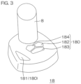
- FIG. 3 is a perspective view showing the structure of the joystick unit 18 by way of example.
- the joystick unit 18 includes the joystick 8, which can be inclined forward, backward, leftward, and rightward (i.e., in all 360-degree directions) and can be pivoted (twisted) about its axis.
- the joystick unit 18 further includes the operation buttons 180.
- the operation buttons 180 include a joystick button 181 and holding mode setting buttons 182 to 184.
- the joystick button 181 is an operator to be operated by the user to select a control mode (watercraft maneuvering mode) utilizing the joystick 8, i.e., the joystick mode.
- the holding mode setting buttons 182, 183, 184 are operation buttons to be operated by the user to select position/azimuth holding control modes (examples of an automatic watercraft maneuvering mode). More specifically, the holding mode setting button 182 is operated to select a fixed point holding mode (Stay Point TM ) in which the position and the bow azimuth (or the stern azimuth) of the watercraft 1 are maintained. The holding mode setting button 183 is operated to select a position holding mode (Fish Point TM ) in which the position of the watercraft 1 is maintained but the bow azimuth (or the stern azimuth) of the watercraft 1 is not maintained. The holding mode setting button 184 is operated to select an azimuth holding mode (Drift Point TM ) in which the bow azimuth (or the stern azimuth) of the watercraft 1 is maintained but the position of the watercraft 1 is not maintained.
- a fixed point holding mode Stay Point TM
- the holding mode setting button 183 is operated to select a position holding mode
- the engine ECUs 21 of the outboard motors OM drive the shift actuators 28 and the throttle actuators 27 according to the propulsive force commands (the shift commands and the output commands) applied from the remote control ECUs 51 to the engine ECUs 21.
- the shift positions of the outboard motors OM are each set to the forward shift position, the reverse shift position, or the neutral shift position, and the engine outputs (specifically, the engine rotation speeds) of the outboard motors OM are changed.
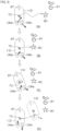
- the bow thruster BT is in a stop state, and the steering angles of the two outboard motors OM are controlled so that the propulsive force action lines 71s, 71p of the outboard motors OM cross each other at the turning center 70 (resistance center) of the hull 2.
- a resultant propulsive force 73 which is the resultant force of the propulsive forces 72s, 72p generated by the two outboard motors OMs, OMp causes the hull 2 to translate (to move laterally) without applying a moment to the hull 2.
- the bow thruster BT is actuated to generate a propulsive force as shown in FIG. 5B .
- the steering angles of the two outboard motors OM are controlled so that the propulsive force action lines 71s, 71p of the outboard motors OM cross each other on the rear side of the turning center 70 (resistance center) of the hull 2.
- the action point of the resultant propulsive force 73 of the propulsive forces 72s, 72p generated by the two outboard motors OM is the intersection of the propulsive force action lines 71s, 71p, so that a moment is applied to the hull 2 about the turning center 70.
- the propulsive force 74 generated by the bow thruster BT also applies a moment to the hull 2 about the turning center 70. Therefore, the propulsive forces 72s, 72p, 74 of the outboard motors OM and the bow thruster BT are controlled so as to balance the moments applied to the hull 2 by the resultant propulsive force 73 of the two outboard motors OM and the propulsive force 74 of the bow thruster BT.
- the hull 2 translates (moves laterally) without the bow turning.
- the overall propulsive force contributable to the translation is greater than in the non-cooperative mode, making it possible to smoothly translate the hull 2.
- the translation mode steering angles are the steering angles of the two outboard motors OM observed when the propulsive force action lines 71s, 71p of the two outboard motors OM cross each other on a line extending anteroposteriorly through the turning center 70 in the hull 2 (on the center line 2a when the turning center 70 is on the center line 2a).
- the translation mode steering angles without the bow turning of the hull 2 are the steering angles of the two outboard motors OM observed when the propulsive force action lines 71s, 71p of the two outboard motors OM cross each other at the turning center 70.
- the translation mode steering angles without the bow turning of the hull 2 are the steering angles of the two outboard motors OM observed when the propulsive force action lines 71s, 71p of the two outboard motors OM cross each other on the rear side of the turning center 70.
- the absolute values of the translation mode steering angles may be equal to the absolute values of the maximum steering angles (e.g., mechanical limit steering angles) of the outboard motors OM.
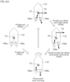
- the hull 2 When the joystick 8 is inclined and pivoted, the hull 2 is in a hull behavior such that the bow is turned in a direction corresponding to the pivoting direction of the joystick 8 while the hull 2 is moved in a direction corresponding to the inclination direction of the joystick 8.
- the hull 2 can be translated with the bow turning depending on the magnitude balance between the propulsive force 74 of the bow thruster BT and the resultant propulsive force 73 of the two outboard motors OM as shown in FIGS. 5C and 5D .
- the hull 2 can be translated with the bow turning by controlling the steering angles of the two outboard motors OM so that the propulsive force action lines 71s, 71p of the two outboard motors OM cross each other on the front side or the rear side of the turning center 70.
- the resultant propulsive force 73 of the two outboard motors OM depends on the directions and the magnitudes of the propulsive forces 72s, 72p of the outboard motors OM, i.e., the steering angles and the outputs (engine rotation speeds) of the respective outboard motors OM. That is, even with the same engine outputs, the resultant propulsive force 73 is relatively reduced by reducing the absolute values of the steering angles to relatively reduce (or narrow) an angle defined between the two outboard motors OM as shown in FIG. 5C . Further, even with the same engine outputs, the resultant propulsive force 73 is relatively increased by increasing the absolute values of the steering angles to relatively increase (or expand) the angle defined between the two outboard motors OM as shown in FIG. 5D .
- the bow of the hull 2 is turned in a direction corresponding to the pivoting direction of the joystick 8 without any substantial position change. That is, the hull 2 is in a hull behavior of fixed point bow turning. Examples of the fixed point bow turning are shown in FIG. 4B .
- the starboard-side outboard motor OMs For the fixed point bow turning in a leftward direction (in a counterclockwise direction as seen in plan), the starboard-side outboard motor OMs is driven forward, and the port-side outboard motor OMp is driven reverse.
- the starboard-side outboard motor OMs For the fixed point bow turning in a rightward direction (in a clockwise direction as seen in plan), the starboard-side outboard motor OMs is driven in reverse, and the port-side outboard motor OMp is driven forward.
- the bow thruster BT In the non-cooperative mode, the bow thruster BT is in the stop state. In the cooperative mode, the bow thruster BT also generates a propulsive force to promote the bow turning. That is, the bow thruster BT applies a leftward propulsive force to the hull 2 for the fixed point bow turning in the leftward direction (in the counterclockwise direction as seen in plan). For the fixed point bow turning in the rightward direction (in the clockwise direction as seen in plan), the bow thruster BT applies a rightward propulsive force to the hull 2.
- the fixed point holding mode (Stay Point TM ), the position holding mode (Fish Point TM ) and the azimuth holding mode (Drift Point TM ) to be respectively selected by operating the holding mode setting buttons 182, 183, and 184 (see FIG. 3 ) as described above are examples of the holding mode.
- the propulsive forces and the steering angles of the outboard motors OM are controlled without any manual operation by the user.
- the cooperative mode the propulsive force of the bow thruster BT is also controlled.
- the main controller 50 controls the outputs and the steering angles of the outboard motors OM based on the position data and the speed data generated by the GPS receiver 52 and the azimuth data outputted by the azimuth sensor 53.
- the propulsive force of the bow thruster BT is also controlled such that the positional change and the azimuthal change of the hull 2 can be reduced or prevented.
- the main controller 50 controls the propulsive forces and the steering angles of the outboard motors OM based on the position data and the speed data generated by the GPS receiver 52.
- the propulsive force of the bow thruster BT is also controlled such that the positional change of the hull 2 is reduced or prevented.
- the movement direction of the hull 2 is detected, for example, based on a change in the position data generated by the GPS receiver 52.
- the steering angles of the outboard motors OM are controlled to maintain the azimuth of the hull 2 so as to direct the bow or the stern in the movement direction. With the azimuth of the hull 2 thus maintained, the propulsive forces are applied anteroposteriorly to the hull 2 to maintain the position of the hull 2.
- the main controller 50 controls the propulsive forces and the steering angles of the outboard motors OM based on the azimuth data generated by the azimuth sensor 53.
- the propulsive force of the bow thruster BT is also controlled such that the azimuthal change of the hull 2 is reduced or prevented.
- the azimuth of the hull 2 may be controlled to be maintained by utilizing only the propulsive force of the bow thruster BT.
- FIG. 6A shows an exemplary control operation to be performed in the fixed point holding mode (Stay Point TM ) in the non-cooperative mode.
- FIG. 6B shows an exemplary control operation to be performed in the fixed point holding mode (Stay Point TM ) in the cooperative mode.
- the main controller 50 acquires the current position of the hull 2 from the GPS receiver 52, and sets the current position as a target position.
- the main controller 50 acquires the current azimuth (the bow azimuth) of the hull 2 (observed when the holding mode setting button 182 is operated) from the azimuth sensor 53, and sets the current azimuth as a target azimuth.
- the target azimuth may be finely adjusted by operating the input device 10 or any of the function switches 61.
- the main controller 50 controls the steering angles of the two outboard motors OM to the translation mode steering angles, and performs a translation control operation to maintain the position of the hull 2 at the target position and performs an azimuth control operation to maintain the azimuth of the hull 2 at the target azimuth.
- an azimuthal offset compensation control operation is also performed. Specifically, the steering angles of the two outboard motors OM are controlled to be maintained at the translation mode steering angles with the intersection of the propulsive force action lines of the two outboard motors OM being offset forward or rearward from the turning center 70.
- the resultant propulsive force 73 of the two outboard motors OM causes the hull 2 to translate, and applies a moment to the hull 2 about the turning center 70.
- both the translation control operation and the azimuth control operation are performed such that the hull 2 is moved to the target position and the bow is turned to the target azimuth.
- a fixed point bow turning control operation is performed to prioritize the azimuthal offset compensation. That is, the fixed point bow turning control operation (a kind of the azimuth control operation) is performed to turn the bow of the hull 2 to the target azimuth.
- the steering angles of the two outboard motors OM are controlled to the bow turning mode steering angles so that the propulsive force action lines of the two outboard motors OM are parallel to the center line 2a.
- one of the two outboard motors OM is driven forward, and the other outboard motor OM is driven in reverse such that the bow of the hull 2 is turned to the target azimuth with the position of the hull 2 fixed.
- the steering angles of the two outboard motors OM are returned to the translation mode steering angles.
- the hull position maintaining control is stopped so that the position of the hull 2 is liable to be significantly changed by the influence of external disturbance (wind and water current).
- the positional offset compensation control operation is performed. That is, the translation control operation is performed to translate the hull 2 to the target position with the azimuth of the hull 2 maintained.
- the steering angles of the two outboard motors OM are controlled so that the propulsive force action lines of the outboard motors OM cross each other on the rear side of the turning center 70.
- one of the two outboard motors OM is driven forward, and the other outboard motor OM is driven in reverse. In this state, the propulsive forces of the two outboard motors OM and the bow thruster BT are properly controlled.
- the hull 2 can be translated to the target position without the bow turning of the hull 2.
- the azimuthal offset compensation control operation is also performed. Specifically, the steering angles of the two outboard motors OM are controlled to be maintained at the translation mode steering angles with the intersection of the propulsive force action lines coinciding with the turning center 70. Thus, the resultant propulsive force 73 of the two outboard motors OM causes the hull 2 to translate, and applies no moment to the hull 2. On the other hand, the bow thruster BT is driven to generate the propulsive force, thus applying a moment to the hull 2 about the turning center 70.
- the translation control operation and the azimuth control operation are both performed by utilizing the outboard motors OM and the bow thruster BT, respectively, such that the hull 2 is moved to the target position and the bow of the hull 2 is turned to the target azimuth.
- the propulsive forces of the outboard motors OM may be partially used for the bow turning of the hull 2.
- the steering angles of the two outboard motors OM are controlled to be maintained at the translation mode steering angles with the intersection of the propulsive force action lines of the two outboard motors OM being offset forward or rearward from the turning center 70.
- the resultant propulsive force 73 of the two outboard motors OM causes the hull 2 to translate, and applies a moment to the hull 2 about the turning center 70. Since the moment is applied to the hull 2 by the propulsive forces of the outboard motors OM and the bow thruster BT, the azimuthal offset can be reduced.
- the fixed point bow turning control operation is performed for the azimuthal offset compensation. That is, the fixed point bow turning control operation (a kind of the azimuth control operation) is performed to turn the bow of the hull 2 to the target azimuth.
- the steering angles of the two outboard motors OM are controlled to the bow turning mode steering angles so that the propulsive force action lines of the two outboard motors OM are parallel to the center line 2a.
- a control mode in which the steering angles of the outboard motors OM are set to the translation mode steering angles for the fixed point holding control is referred to as “translation mode” and a control mode in which the steering angles of the outboard motors OM are set to the bow turning mode steering angles for the fixed point holding control is referred to as “bow turning mode.”
- the positional offset is reduced (first switching condition) or if the propulsive force requirement value for the translation is reduced (second switching condition), the movement speed of the hull 2 is reduced, and the course keeping performance of the hull 2 is reduced. Further, if the azimuthal offset of the hull 2 from the target azimuth is increased, the bow turning requirement value is increased (third switching condition). Therefore, where at least one of the first, second, and third switching conditions to be satisfied in these situations is used as the bow turning mode switching condition, the translation mode can be properly switched to the bow turning mode.
- the third switching condition may be such that the bow turning requirement value is not less than the third threshold, or may be such that the azimuthal offset is not less than the third threshold.
- the mode switching threshold corresponds to the third threshold.
- FIG. 8 shows a specific example of the hull behavior to be observed in the fixed point holding mode in the cooperative mode.
- the hull 2 is translated toward a target position 80 against external disturbance 81 (wind or water current) such that the offset of the position of the hull 2 from the target position 80 (positional offset) is reduced to not greater than the first threshold (a change from State 8A to State 8B in FIG. 8 ).
- the external disturbance is not great, the magnitude of the propulsive force required for the translation (i.e., the propulsive force requirement value) is reduced to less than the second threshold as the hull 2 approaches the target position 80.
- the translation mode is not switched to the bow turning mode, but maintained. Even in the translation mode, a great moment can be applied to the hull 2 by the propulsive force of the bow thruster BT. Therefore, the switching to the bow turning mode is less liable to occur.
- the positional offset can be eliminated as much as possible which may otherwise occur during the bow turning mode, so that the fixed point holding control can be highly precisely performed.
- the outboard motors OM and the bow thruster BT apply moments to the hull 2 in the bow turning mode such that the azimuthal offset can be speedily reduced. Therefore, the control operation in the bow turning mode can be finished in a short period of time to switch from the bow turning mode to the translation mode.
- the positional offset in the bow turning mode can be reduced. This is also contributable to the highly precise fixed point holding control.
- FIG. 9 shows a specific example of the hull behavior to be observed in the fixed point holding control in the non-cooperative mode. Since the bow thruster BT is in the stop state, the translation and the bow turning of the hull 2 are controlled solely by the propulsive forces of the outboard motors OM in the translation mode. By performing the control operation according to the translation mode, the hull 2 is translated toward a target position 80 against external disturbance 81 (wind or water current) such that the offset of the position of the hull 2 from the target position 80 (positional offset) is reduced to not greater than the first threshold (a change from State 9A to State 9B in FIG. 9 ).
- external disturbance 81 wind or water current
- the magnitude of the propulsive force required for the translation i.e., the propulsive force requirement value
- the second threshold the magnitude of the propulsive force required for the translation
- the translation mode is switched to the bow turning mode (State 9D in FIG. 9 ).
- the propulsive forces of the outboard motors OM also apply moments to the hull 2 so that the azimuth of the hull 2 can be adjusted to the target azimuth.
- the bow thruster BT is able to generate the propulsive force only laterally leftward and rightward by way of example.
- a steerable propulsion device such as an electric trolling motor may be provided at the bow instead of the propulsion device that is able to generate the propulsive force only laterally leftward and rightward.
- the bow thruster may be a propulsion device provided at the bow and able to generate the propulsive force laterally leftward and rightward and further generate the propulsive force in directions other than the leftward and rightward directions.
- the watercraft propulsion system 100 includes the cooperative mode in which the outboard motors OM and the bow thruster BT are controlled in a cooperative manner, and the non-cooperative mode in which the cooperative control is not performed by way of example.
- the non-cooperative mode may be omitted.
Landscapes
- Chemical & Material Sciences (AREA)
- Engineering & Computer Science (AREA)
- Combustion & Propulsion (AREA)
- Mechanical Engineering (AREA)
- Ocean & Marine Engineering (AREA)
- Control Of Position, Course, Altitude, Or Attitude Of Moving Bodies (AREA)
Claims (8)
- Antriebssystem (100) für ein Wasserfahrzeug, umfassend:ein Bugstrahlruder (BT) an einem Bug eines Rumpfes (2) zum Erzeugen einer seitlichen Antriebskraft,eine Antriebsvorrichtung (OM) an einem Heck (3) des Rumpfes (2) mit einem variablen Lenkwinkel undeine Steuereinheit (50), die so konfiguriert oder programmiert ist, dass sie die Antriebskraft des Bugstrahlruders (BT) steuert und den Lenkwinkel und die Antriebskraft der Antriebsvorrichtung (OM) steuert,dadurch gekennzeichnet, dassdie Steuereinheit (50) so konfiguriert oder programmiert ist, dass sie die Antriebskraft des Bugstrahlruders (BT) steuert und den Lenkwinkel und die Antriebskraft der Antriebsvorrichtung steuert, um eine Steuerung zum Beibehalten eines Fixpunkts durchzuführen, um eine Position und ein Azimut des Rumpfes (2) aufrechtzuerhalten,die Steuerung zum Beibehalten eines Fixpunkts umfasst: einen Translationsmodus, in dem die Position des Rumpfes durch Steuern der Antriebskraft der Antriebsvorrichtung (OM) mit dem auf einen Translationsmodus-Lenkwinkel eingestellten Lenkwinkel der Antriebsvorrichtung (OM) zum Translatieren des Rumpfes (2) aufrechterhalten wird und das Azimut des Rumpfes durch Steuern der Antriebskraft des Bugstrahlruders (BT) eingestellt wird, und einen Bugdrehmodus, in dem das Azimut des Rumpfes durch Steuern der Antriebskräfte des Bugstrahlruders (BT) und der Antriebsvorrichtung (OM) mit dem Lenkwinkel der Antriebsvorrichtung (OM), eingestellt auf einen Bugdrehmodus-Lenkwinkel, einreguliert wird, um den Rumpf (2) zu drehen,die Steuereinrichtung (50) so konfiguriert oder programmiert ist, dass sie während der Steuerung zum Beibehalten eines Fixpunkts auf der Grundlage einer vorbestimmten Umschaltbedingung zwischen dem Translationsmodus und dem Bugdrehmodus umschaltet,die Umschaltbedingung eine Umschaltbedingung in den Bugdrehmodus zum Umschalten vom Translationsmodus in den Bugdrehmodus umfasst unddie Umschaltbedingung in den Bugdrehmodus mindestens eine Bedingung umfasst, welche ausgewählt ist aus der Gruppe bestehend aus: einer ersten Umschaltbedingung dergestalt, dass ein Positionsversatz des Rumpfes (2) von einer Sollposition kleiner als ein erster Schwellenwert ist, einer zweiten Umschaltbedingung dergestalt, dass ein Bedarfswert für die Antriebskraft zum Translatieren des Rumpfes (2) kleiner als ein zweiter Schwellenwert ist, oder einer dritten Umschaltbedingung dergestalt, dass ein Bugdrehbedarfswert für die Bugdrehung des Rumpfes (2) oder ein Versatz des Azimuts des Rumpfes (2) von einem Zielazimut nicht kleiner als ein dritter Schwellenwert ist, unddie Umschaltbedingung eine Umschaltbedingung in den Translationsmodus zum Umschalten vom Bugdrehmodus in den Translationsmodus umfasst, unddie Umschaltbedingung in den Translationsmodus mindestens eine vierte Umschaltbedingung dergestalt, dass ein Bugdrehbedarfswert zum Drehen des Bugs des Rumpfes (2) oder ein Versatz des Azimuts des Rumpfes (2) von einem Zielazimut nicht größer als ein vierter Schwellenwert ist, und eine fünfte Umschaltbedingung dergestalt, dass ein Bedarfswert für die Antriebskraft zum Translatieren des Rumpfes (2) nicht kleiner als ein fünfter Schwellenwert ist, umfasst.
- Antriebssystem (100) für ein Wasserfahrzeug gemäß Anspruch 1, wobei die Umschaltbedingung in den Bugdrehmodus eine Bedingung dergestalt, dass die erste Umschaltbedingung, die zweite Umschaltbedingung und die dritte Umschaltbedingung für nicht kürzer als eine vorbestimmte Zeitdauer kontinuierlich erfüllt sind, umfasst.
- Antriebssystem (100) für ein Wasserfahrzeug gemäß Anspruch 1 oder 2, wobei der Bugdrehmodus in den Translationsmodus umgeschaltet wird, wenn mindestens eine der vierten Umschaltbedingung oder der fünften Umschaltbedingung erfüllt ist.
- Antriebssystem (100) für ein Wasserfahrzeug gemäß einem der Ansprüche 1 bis 3, wobeidie Antriebsvorrichtung mindestens zwei Antriebsvorrichtungen (OM) mit jeweils einem variablen Lenkwinkel umfasst undder Lenkwinkel im Translationsmodus Translationsmodus-Lenkwinkel dergestalt, dass sich die Wirkungslinien der Antriebskraft (71s, 71p) der beiden Antriebsvorrichtungen (OM) einander im Rumpf (2) kreuzen, umfasst.
- Antriebssystem (100) für ein Wasserfahrzeug gemäß Anspruch 4, wobei der Lenkwinkel im Translationsmodus Translationsmodus-Lenkwinkel dergestalt, dass sich die Wirkungslinien der Antriebskraft (71s, 71p) der beiden Antriebsvorrichtungen (OM) einander an einer Position kreuzen, welche näher am Heck (3) als an einem Drehpunkt des Rumpfes (2) liegt, umfasst.
- Antriebssystem (100) für ein Wasserfahrzeug gemäß einem der Ansprüche 1 bis 5, wobeidie Antriebsvorrichtung mindestens zwei Antriebsvorrichtungen (OM) mit jeweils einem variablen Lenkwinkel umfasst undder Lenkwinkel im Bugdrehmodus Bugdrehmodus-Lenkwinkel dergestalt, dass die Wirkungslinien der Antriebskraft (71s, 71p) der beiden Antriebsvorrichtungen (OM) parallel oder im Wesentlichen parallel zueinander sind, umfasst.
- Antriebssystem (100) für ein Wasserfahrzeug gemäß einem der Ansprüche 1 bis 6, wobeidie Antriebsvorrichtung (OM) mindestens zwei Antriebsvorrichtungen (OM) mit jeweils einem variablen Lenkwinkel umfasst, undeine der beiden Antriebsvorrichtungen (OM) im Translationsmodus und im Bugdrehmodus vorwärts angetrieben wird und die andere der beiden Antriebsvorrichtungen (OM) rückwärts angetrieben wird.
- Wasserfahrzeug (1), umfassend:einen Rumpf (2) unddas Antriebssystem (100) für ein Wasserfahrzeug gemäß einem der Ansprüche 1 bis 7 an dem Rumpf (2).
Applications Claiming Priority (1)
| Application Number | Priority Date | Filing Date | Title |
|---|---|---|---|
| JP2022178982A JP2024068483A (ja) | 2022-11-08 | 2022-11-08 | 船舶推進システムおよびそれを備える船舶 |
Publications (2)
| Publication Number | Publication Date |
|---|---|
| EP4375182A1 EP4375182A1 (de) | 2024-05-29 |
| EP4375182B1 true EP4375182B1 (de) | 2025-07-02 |
Family
ID=88745769
Family Applications (1)
| Application Number | Title | Priority Date | Filing Date |
|---|---|---|---|
| EP23208428.5A Active EP4375182B1 (de) | 2022-11-08 | 2023-11-08 | Wasserfahrzeugantriebssystem und wasserfahrzeug mit dem wasserfahrzeugantriebssystem |
Country Status (3)
| Country | Link |
|---|---|
| US (1) | US12466530B2 (de) |
| EP (1) | EP4375182B1 (de) |
| JP (1) | JP2024068483A (de) |
Families Citing this family (1)
| Publication number | Priority date | Publication date | Assignee | Title |
|---|---|---|---|---|
| US12168503B2 (en) | 2023-03-20 | 2024-12-17 | The Yacht Group, LLC | System for providing thruster effect on a vessel |
Family Cites Families (18)
| Publication number | Priority date | Publication date | Assignee | Title |
|---|---|---|---|---|
| JPH01148696A (ja) | 1987-12-03 | 1989-06-12 | Hitachi Zosen Corp | 船舶の定点保持装置 |
| JPH10226395A (ja) | 1997-02-17 | 1998-08-25 | Nissan Motor Co Ltd | 船舶の船位制御装置 |
| JP4339016B2 (ja) * | 2002-05-20 | 2009-10-07 | 川崎重工業株式会社 | 推力配分方法及び推力配分装置 |
| JP4295645B2 (ja) | 2004-03-11 | 2009-07-15 | 三井造船株式会社 | ウォータジェット推進船の自動定点保持装置 |
| JP5191199B2 (ja) | 2006-10-06 | 2013-04-24 | ヤマハ発動機株式会社 | 船舶用推進装置の制御装置、ならびにそれを用いた航走支援システムおよび船舶 |
| WO2008140654A1 (en) * | 2007-05-11 | 2008-11-20 | Exxonmobil Upstream Research Company | Automatic ice-vaning ship |
| JP5226355B2 (ja) * | 2008-03-31 | 2013-07-03 | 三井造船株式会社 | 1軸1舵バウスラスタ船の定点保持システムおよび定点保持方法 |
| JP5481059B2 (ja) * | 2008-11-28 | 2014-04-23 | ヤマハ発動機株式会社 | 操船支援装置およびそれを備えた船舶 |
| JP5982716B2 (ja) | 2012-08-08 | 2016-08-31 | ヤマハ発動機株式会社 | 船舶推進制御装置、船舶推進装置および船舶 |
| JP6664171B2 (ja) * | 2015-09-07 | 2020-03-13 | ジャパン・ハムワージ株式会社 | 船舶操縦装置 |
| JP6421111B2 (ja) * | 2015-12-11 | 2018-11-07 | ヤンマー株式会社 | 操船装置 |
| JP6911161B2 (ja) | 2018-02-15 | 2021-07-28 | 本田技研工業株式会社 | 操船支援装置及び船外機 |
| WO2020069750A1 (en) | 2018-10-05 | 2020-04-09 | Cpac Systems Ab | Thruster assisted docking |
| JP2020168921A (ja) | 2019-04-02 | 2020-10-15 | ヤマハ発動機株式会社 | 船舶用推進システムおよび船舶 |
| US11480966B2 (en) * | 2020-03-10 | 2022-10-25 | Brunswick Corporation | Marine propulsion control system and method |
| JP7249657B2 (ja) * | 2020-06-03 | 2023-03-31 | ジャパン・ハムワージ株式会社 | 船舶の制御法 |
| JP7664060B2 (ja) * | 2021-03-12 | 2025-04-17 | ヤンマーホールディングス株式会社 | 操船装置、及び船舶 |
| JP7141777B1 (ja) * | 2022-02-14 | 2022-09-26 | ジャパン・ハムワージ株式会社 | 自動着桟機能を有する一軸二舵船 |
-
2022
- 2022-11-08 JP JP2022178982A patent/JP2024068483A/ja active Pending
-
2023
- 2023-11-06 US US18/387,085 patent/US12466530B2/en active Active
- 2023-11-08 EP EP23208428.5A patent/EP4375182B1/de active Active
Also Published As
| Publication number | Publication date |
|---|---|
| US12466530B2 (en) | 2025-11-11 |
| US20240149998A1 (en) | 2024-05-09 |
| JP2024068483A (ja) | 2024-05-20 |
| EP4375182A1 (de) | 2024-05-29 |
Similar Documents
| Publication | Publication Date | Title |
|---|---|---|
| EP3805088A1 (de) | Verfahren zur steuerung von lagekontrollklappen eines seeschiffs, steuerungssystem zur steuerung von lagekontrollklappen, die an einem seeschiff montiert werden, und seeschiff | |
| EP3406516B1 (de) | Schiffmanövriervorrichtung und schiff damit | |
| EP4357237B1 (de) | Wasserfahrzeugantriebssystem, wasserfahrzeug und wasserfahrzeugantriebssteuerungsverfahren | |
| EP4368492B1 (de) | Wasserfahrzeugantriebssystem und wasserfahrzeug mit dem wasserfahrzeugantriebssystem | |
| EP4375182B1 (de) | Wasserfahrzeugantriebssystem und wasserfahrzeug mit dem wasserfahrzeugantriebssystem | |
| EP4365074B1 (de) | Wasserfahrzeugantriebssystem, wasserfahrzeug und wasserfahrzeugantriebssteuerungsverfahren | |
| EP4368493A1 (de) | Wasserfahrzeugantriebssystem und wasserfahrzeug mit dem wasserfahrzeugantriebssystem | |
| EP4378815A1 (de) | Wasserfahrzeugantriebssystem und wasserfahrzeug mit dem wasserfahrzeugantriebssystem | |
| US20250050992A1 (en) | Watercraft propulsion system, and watercraft | |
| US20250050991A1 (en) | Watercraft propulsion system, and watercraft | |
| US20240239464A1 (en) | Watercraft maneuvering system and watercraft including the watercraft maneuvering system | |
| US20250050998A1 (en) | Watercraft propulsion system and watercraft | |
| US20250050994A1 (en) | Watercraft propulsion system and watercraft | |
| US12503214B2 (en) | Watercraft maneuvering system and watercraft including the watercraft maneuvering system | |
| EP4524023B1 (de) | Schiffsantriebssystem zur bewegung eines wasserfahrzeugs in seitlicher richtung und steuerungsverfahren dafür | |
| US20240239463A1 (en) | Watercraft maneuvering system and watercraft including the watercraft maneuvering system | |
| US20250388296A1 (en) | Marine vessel and control device therefor | |
| US12589852B2 (en) | Ship steering control device | |
| US20240400185A1 (en) | Ship steering control device |
Legal Events
| Date | Code | Title | Description |
|---|---|---|---|
| PUAI | Public reference made under article 153(3) epc to a published international application that has entered the european phase |
Free format text: ORIGINAL CODE: 0009012 |
|
| STAA | Information on the status of an ep patent application or granted ep patent |
Free format text: STATUS: THE APPLICATION HAS BEEN PUBLISHED |
|
| AK | Designated contracting states |
Kind code of ref document: A1 Designated state(s): AL AT BE BG CH CY CZ DE DK EE ES FI FR GB GR HR HU IE IS IT LI LT LU LV MC ME MK MT NL NO PL PT RO RS SE SI SK SM TR |
|
| P01 | Opt-out of the competence of the unified patent court (upc) registered |
Free format text: CASE NUMBER: APP_37573/2024 Effective date: 20240624 |
|
| STAA | Information on the status of an ep patent application or granted ep patent |
Free format text: STATUS: REQUEST FOR EXAMINATION WAS MADE |
|
| 17P | Request for examination filed |
Effective date: 20241004 |
|
| RBV | Designated contracting states (corrected) |
Designated state(s): AL AT BE BG CH CY CZ DE DK EE ES FI FR GB GR HR HU IE IS IT LI LT LU LV MC ME MK MT NL NO PL PT RO RS SE SI SK SM TR |
|
| GRAP | Despatch of communication of intention to grant a patent |
Free format text: ORIGINAL CODE: EPIDOSNIGR1 |
|
| STAA | Information on the status of an ep patent application or granted ep patent |
Free format text: STATUS: GRANT OF PATENT IS INTENDED |
|
| INTG | Intention to grant announced |
Effective date: 20250219 |
|
| GRAS | Grant fee paid |
Free format text: ORIGINAL CODE: EPIDOSNIGR3 |
|
| GRAA | (expected) grant |
Free format text: ORIGINAL CODE: 0009210 |
|
| STAA | Information on the status of an ep patent application or granted ep patent |
Free format text: STATUS: THE PATENT HAS BEEN GRANTED |
|
| AK | Designated contracting states |
Kind code of ref document: B1 Designated state(s): AL AT BE BG CH CY CZ DE DK EE ES FI FR GB GR HR HU IE IS IT LI LT LU LV MC ME MK MT NL NO PL PT RO RS SE SI SK SM TR |
|
| REG | Reference to a national code |
Ref country code: GB Ref legal event code: FG4D |
|
| REG | Reference to a national code |
Ref country code: CH Ref legal event code: EP |
|
| REG | Reference to a national code |
Ref country code: DE Ref legal event code: R096 Ref document number: 602023004511 Country of ref document: DE |
|
| REG | Reference to a national code |
Ref country code: IE Ref legal event code: FG4D |
|
| REG | Reference to a national code |
Ref country code: NL Ref legal event code: MP Effective date: 20250702 |
|
| PG25 | Lapsed in a contracting state [announced via postgrant information from national office to epo] |
Ref country code: PT Free format text: LAPSE BECAUSE OF FAILURE TO SUBMIT A TRANSLATION OF THE DESCRIPTION OR TO PAY THE FEE WITHIN THE PRESCRIBED TIME-LIMIT Effective date: 20251103 |
|
| PG25 | Lapsed in a contracting state [announced via postgrant information from national office to epo] |
Ref country code: NL Free format text: LAPSE BECAUSE OF FAILURE TO SUBMIT A TRANSLATION OF THE DESCRIPTION OR TO PAY THE FEE WITHIN THE PRESCRIBED TIME-LIMIT Effective date: 20250702 |
|
| REG | Reference to a national code |
Ref country code: AT Ref legal event code: MK05 Ref document number: 1808967 Country of ref document: AT Kind code of ref document: T Effective date: 20250702 |
|
| PG25 | Lapsed in a contracting state [announced via postgrant information from national office to epo] |
Ref country code: IS Free format text: LAPSE BECAUSE OF FAILURE TO SUBMIT A TRANSLATION OF THE DESCRIPTION OR TO PAY THE FEE WITHIN THE PRESCRIBED TIME-LIMIT Effective date: 20251102 |
|
| PGFP | Annual fee paid to national office [announced via postgrant information from national office to epo] |
Ref country code: DE Payment date: 20251119 Year of fee payment: 3 |
|
| PG25 | Lapsed in a contracting state [announced via postgrant information from national office to epo] |
Ref country code: NO Free format text: LAPSE BECAUSE OF FAILURE TO SUBMIT A TRANSLATION OF THE DESCRIPTION OR TO PAY THE FEE WITHIN THE PRESCRIBED TIME-LIMIT Effective date: 20251002 |
|
| REG | Reference to a national code |
Ref country code: LT Ref legal event code: MG9D |
|
| PG25 | Lapsed in a contracting state [announced via postgrant information from national office to epo] |
Ref country code: AT Free format text: LAPSE BECAUSE OF FAILURE TO SUBMIT A TRANSLATION OF THE DESCRIPTION OR TO PAY THE FEE WITHIN THE PRESCRIBED TIME-LIMIT Effective date: 20250702 |
|
| PG25 | Lapsed in a contracting state [announced via postgrant information from national office to epo] |
Ref country code: FI Free format text: LAPSE BECAUSE OF FAILURE TO SUBMIT A TRANSLATION OF THE DESCRIPTION OR TO PAY THE FEE WITHIN THE PRESCRIBED TIME-LIMIT Effective date: 20250702 |
|
| PGFP | Annual fee paid to national office [announced via postgrant information from national office to epo] |
Ref country code: IT Payment date: 20251201 Year of fee payment: 3 |
|
| PG25 | Lapsed in a contracting state [announced via postgrant information from national office to epo] |
Ref country code: HR Free format text: LAPSE BECAUSE OF FAILURE TO SUBMIT A TRANSLATION OF THE DESCRIPTION OR TO PAY THE FEE WITHIN THE PRESCRIBED TIME-LIMIT Effective date: 20250702 |
|
| PGFP | Annual fee paid to national office [announced via postgrant information from national office to epo] |
Ref country code: FR Payment date: 20251126 Year of fee payment: 3 |
|
| PG25 | Lapsed in a contracting state [announced via postgrant information from national office to epo] |
Ref country code: GR Free format text: LAPSE BECAUSE OF FAILURE TO SUBMIT A TRANSLATION OF THE DESCRIPTION OR TO PAY THE FEE WITHIN THE PRESCRIBED TIME-LIMIT Effective date: 20251003 |
|
| PG25 | Lapsed in a contracting state [announced via postgrant information from national office to epo] |
Ref country code: SE Free format text: LAPSE BECAUSE OF FAILURE TO SUBMIT A TRANSLATION OF THE DESCRIPTION OR TO PAY THE FEE WITHIN THE PRESCRIBED TIME-LIMIT Effective date: 20250702 Ref country code: CZ Free format text: LAPSE BECAUSE OF FAILURE TO SUBMIT A TRANSLATION OF THE DESCRIPTION OR TO PAY THE FEE WITHIN THE PRESCRIBED TIME-LIMIT Effective date: 20250702 |
|
| PG25 | Lapsed in a contracting state [announced via postgrant information from national office to epo] |
Ref country code: LV Free format text: LAPSE BECAUSE OF FAILURE TO SUBMIT A TRANSLATION OF THE DESCRIPTION OR TO PAY THE FEE WITHIN THE PRESCRIBED TIME-LIMIT Effective date: 20250702 |
|
| PG25 | Lapsed in a contracting state [announced via postgrant information from national office to epo] |
Ref country code: PL Free format text: LAPSE BECAUSE OF FAILURE TO SUBMIT A TRANSLATION OF THE DESCRIPTION OR TO PAY THE FEE WITHIN THE PRESCRIBED TIME-LIMIT Effective date: 20250702 Ref country code: BG Free format text: LAPSE BECAUSE OF FAILURE TO SUBMIT A TRANSLATION OF THE DESCRIPTION OR TO PAY THE FEE WITHIN THE PRESCRIBED TIME-LIMIT Effective date: 20250702 |
|
| PG25 | Lapsed in a contracting state [announced via postgrant information from national office to epo] |
Ref country code: RS Free format text: LAPSE BECAUSE OF FAILURE TO SUBMIT A TRANSLATION OF THE DESCRIPTION OR TO PAY THE FEE WITHIN THE PRESCRIBED TIME-LIMIT Effective date: 20251002 |
|
| PG25 | Lapsed in a contracting state [announced via postgrant information from national office to epo] |
Ref country code: ES Free format text: LAPSE BECAUSE OF FAILURE TO SUBMIT A TRANSLATION OF THE DESCRIPTION OR TO PAY THE FEE WITHIN THE PRESCRIBED TIME-LIMIT Effective date: 20250702 |
|
| PG25 | Lapsed in a contracting state [announced via postgrant information from national office to epo] |
Ref country code: RO Free format text: LAPSE BECAUSE OF FAILURE TO SUBMIT A TRANSLATION OF THE DESCRIPTION OR TO PAY THE FEE WITHIN THE PRESCRIBED TIME-LIMIT Effective date: 20250702 |