EP4375072B1 - Tintenliefergerät - Google Patents
Tintenliefergerät Download PDFInfo
- Publication number
- EP4375072B1 EP4375072B1 EP23212077.4A EP23212077A EP4375072B1 EP 4375072 B1 EP4375072 B1 EP 4375072B1 EP 23212077 A EP23212077 A EP 23212077A EP 4375072 B1 EP4375072 B1 EP 4375072B1
- Authority
- EP
- European Patent Office
- Prior art keywords
- reservoir
- horizontal
- ink
- vertical
- pipe
- Prior art date
- Legal status (The legal status is an assumption and is not a legal conclusion. Google has not performed a legal analysis and makes no representation as to the accuracy of the status listed.)
- Active
Links
Images






Classifications
-
- B—PERFORMING OPERATIONS; TRANSPORTING
- B41—PRINTING; LINING MACHINES; TYPEWRITERS; STAMPS
- B41J—TYPEWRITERS; SELECTIVE PRINTING MECHANISMS, i.e. MECHANISMS PRINTING OTHERWISE THAN FROM A FORME; CORRECTION OF TYPOGRAPHICAL ERRORS
- B41J2/00—Typewriters or selective printing mechanisms characterised by the printing or marking process for which they are designed
- B41J2/005—Typewriters or selective printing mechanisms characterised by the printing or marking process for which they are designed characterised by bringing liquid or particles selectively into contact with a printing material
- B41J2/01—Ink jet
- B41J2/17—Ink jet characterised by ink handling
- B41J2/175—Ink supply systems ; Circuit parts therefor
- B41J2/17503—Ink cartridges
- B41J2/17513—Inner structure
-
- B—PERFORMING OPERATIONS; TRANSPORTING
- B41—PRINTING; LINING MACHINES; TYPEWRITERS; STAMPS
- B41J—TYPEWRITERS; SELECTIVE PRINTING MECHANISMS, i.e. MECHANISMS PRINTING OTHERWISE THAN FROM A FORME; CORRECTION OF TYPOGRAPHICAL ERRORS
- B41J2/00—Typewriters or selective printing mechanisms characterised by the printing or marking process for which they are designed
- B41J2/005—Typewriters or selective printing mechanisms characterised by the printing or marking process for which they are designed characterised by bringing liquid or particles selectively into contact with a printing material
- B41J2/01—Ink jet
- B41J2/17—Ink jet characterised by ink handling
- B41J2/18—Ink recirculation systems
- B41J2/185—Ink-collectors; Ink-catchers
-
- B—PERFORMING OPERATIONS; TRANSPORTING
- B41—PRINTING; LINING MACHINES; TYPEWRITERS; STAMPS
- B41J—TYPEWRITERS; SELECTIVE PRINTING MECHANISMS, i.e. MECHANISMS PRINTING OTHERWISE THAN FROM A FORME; CORRECTION OF TYPOGRAPHICAL ERRORS
- B41J2/00—Typewriters or selective printing mechanisms characterised by the printing or marking process for which they are designed
- B41J2/005—Typewriters or selective printing mechanisms characterised by the printing or marking process for which they are designed characterised by bringing liquid or particles selectively into contact with a printing material
- B41J2/01—Ink jet
- B41J2/17—Ink jet characterised by ink handling
- B41J2/1721—Collecting waste ink; Collectors therefor
-
- B—PERFORMING OPERATIONS; TRANSPORTING
- B41—PRINTING; LINING MACHINES; TYPEWRITERS; STAMPS
- B41J—TYPEWRITERS; SELECTIVE PRINTING MECHANISMS, i.e. MECHANISMS PRINTING OTHERWISE THAN FROM A FORME; CORRECTION OF TYPOGRAPHICAL ERRORS
- B41J2/00—Typewriters or selective printing mechanisms characterised by the printing or marking process for which they are designed
- B41J2/005—Typewriters or selective printing mechanisms characterised by the printing or marking process for which they are designed characterised by bringing liquid or particles selectively into contact with a printing material
- B41J2/01—Ink jet
- B41J2/17—Ink jet characterised by ink handling
- B41J2/1721—Collecting waste ink; Collectors therefor
- B41J2/1728—Closed waste ink collectors
- B41J2/1735—Closed waste ink collectors with ink supply tank in common containers
-
- B—PERFORMING OPERATIONS; TRANSPORTING
- B41—PRINTING; LINING MACHINES; TYPEWRITERS; STAMPS
- B41J—TYPEWRITERS; SELECTIVE PRINTING MECHANISMS, i.e. MECHANISMS PRINTING OTHERWISE THAN FROM A FORME; CORRECTION OF TYPOGRAPHICAL ERRORS
- B41J2/00—Typewriters or selective printing mechanisms characterised by the printing or marking process for which they are designed
- B41J2/005—Typewriters or selective printing mechanisms characterised by the printing or marking process for which they are designed characterised by bringing liquid or particles selectively into contact with a printing material
- B41J2/01—Ink jet
- B41J2/17—Ink jet characterised by ink handling
- B41J2/175—Ink supply systems ; Circuit parts therefor
- B41J2/17503—Ink cartridges
- B41J2/17553—Outer structure
-
- B—PERFORMING OPERATIONS; TRANSPORTING
- B41—PRINTING; LINING MACHINES; TYPEWRITERS; STAMPS
- B41J—TYPEWRITERS; SELECTIVE PRINTING MECHANISMS, i.e. MECHANISMS PRINTING OTHERWISE THAN FROM A FORME; CORRECTION OF TYPOGRAPHICAL ERRORS
- B41J2/00—Typewriters or selective printing mechanisms characterised by the printing or marking process for which they are designed
- B41J2/005—Typewriters or selective printing mechanisms characterised by the printing or marking process for which they are designed characterised by bringing liquid or particles selectively into contact with a printing material
- B41J2/01—Ink jet
- B41J2/17—Ink jet characterised by ink handling
- B41J2/175—Ink supply systems ; Circuit parts therefor
- B41J2/17596—Ink pumps, ink valves
-
- B—PERFORMING OPERATIONS; TRANSPORTING
- B41—PRINTING; LINING MACHINES; TYPEWRITERS; STAMPS
- B41J—TYPEWRITERS; SELECTIVE PRINTING MECHANISMS, i.e. MECHANISMS PRINTING OTHERWISE THAN FROM A FORME; CORRECTION OF TYPOGRAPHICAL ERRORS
- B41J2/00—Typewriters or selective printing mechanisms characterised by the printing or marking process for which they are designed
- B41J2/005—Typewriters or selective printing mechanisms characterised by the printing or marking process for which they are designed characterised by bringing liquid or particles selectively into contact with a printing material
- B41J2/01—Ink jet
- B41J2/17—Ink jet characterised by ink handling
- B41J2/18—Ink recirculation systems
-
- B—PERFORMING OPERATIONS; TRANSPORTING
- B41—PRINTING; LINING MACHINES; TYPEWRITERS; STAMPS
- B41J—TYPEWRITERS; SELECTIVE PRINTING MECHANISMS, i.e. MECHANISMS PRINTING OTHERWISE THAN FROM A FORME; CORRECTION OF TYPOGRAPHICAL ERRORS
- B41J2/00—Typewriters or selective printing mechanisms characterised by the printing or marking process for which they are designed
- B41J2/005—Typewriters or selective printing mechanisms characterised by the printing or marking process for which they are designed characterised by bringing liquid or particles selectively into contact with a printing material
- B41J2/01—Ink jet
- B41J2/17—Ink jet characterised by ink handling
- B41J2/19—Ink jet characterised by ink handling for removing air bubbles
-
- B—PERFORMING OPERATIONS; TRANSPORTING
- B41—PRINTING; LINING MACHINES; TYPEWRITERS; STAMPS
- B41J—TYPEWRITERS; SELECTIVE PRINTING MECHANISMS, i.e. MECHANISMS PRINTING OTHERWISE THAN FROM A FORME; CORRECTION OF TYPOGRAPHICAL ERRORS
- B41J2/00—Typewriters or selective printing mechanisms characterised by the printing or marking process for which they are designed
- B41J2/005—Typewriters or selective printing mechanisms characterised by the printing or marking process for which they are designed characterised by bringing liquid or particles selectively into contact with a printing material
- B41J2/01—Ink jet
- B41J2/17—Ink jet characterised by ink handling
- B41J2/20—Ink jet characterised by ink handling for preventing or detecting contamination of compounds
Definitions
- the present invention relates to an ink supplier that supplies ink to a plurality of heads in an ink-jet printing apparatus.
- the ink touches outside air at a nozzle provided at a head.
- agglomeration is caused easily as a result of evaporation of a solvent.
- a circulation system of supplying ink to a head and collecting the ink from the head is employed, thereby reducing remaining of the ink in the head to suppress agglomeration at a nozzle.
- a printing apparatus employing the circulation system is described in Japanese Patent Application Laid-Open No. 2022-52068 , for example.
- the present invention has been made in view of the foregoing circumstances, and is intended to provide a technique allowing a precipitate in a reservoir to be efficiently prevented from entering a head.
- a first aspect of the present invention is intended for an ink supplier that supplies ink to a plurality of heads in an ink-jet printing apparatus, comprising: a supply reservoir storing the ink to be supplied to the plurality of heads; and a discharge pipe having a pump and used for discharging the ink from the supply reservoir.
- the supply reservoir includes: a first horizontal reservoir having a cylindrical shape extending in a direction of alignment of the plurality of heads, and having a plurality of supply ports each communicating with one of the plurality of heads; and a first vertical reservoir having a side surface provided with a first opening directly or indirectly communicating with one end of the first horizontal reservoir, and having a cylindrical shape with a closed bottom larger in a top-bottom direction than the first horizontal reservoir.
- the first horizontal reservoir has a bottom surface that is tilted from a horizontal direction at an angle of tilt equal to or greater than 0.3° in such a manner as to extend downward from the one end toward the other end.
- the first horizontal reservoir includes a first discharge port provided at a bottom portion of the first horizontal reservoir at the other end and communicably connected to the discharge pipe.
- the first vertical reservoir has a bottom surface of a planar shape, the bottom surface of the first vertical reservoir is tilted from the horizontal direction at an angle of tilt equal to or greater than 0.3° in such a manner as to extend upward with distance from the first horizontal reservoir, and the second discharge port is provided at a bottom portion of the first vertical reservoir at an end adjacent to the first horizontal reservoir.
- the second horizontal reservoir has a bottom surface that is tilted from the horizontal direction at an angle of tilt equal to or greater than 0.3° in such a manner as to extend downward from the one end toward the other end.
- the second horizontal reservoir includes a third discharge port provided at a bottom portion of the second horizontal reservoir at the other end and communicably connected to the discharge pipe.
- the second vertical reservoir includes a fourth discharge port provided at a lowermost point at a bottom portion of the second vertical reservoir and communicably connected to the discharge pipe.
- the second vertical reservoir has a bottom surface of a planar shape, the bottom surface of the second vertical reservoir is tilted from the horizontal direction at an angle of tilt equal to or greater than 0.3° in such a manner as to extend upward with distance from the second horizontal reservoir, and the fourth discharge port is provided at a bottom portion of the second vertical reservoir at an end adjacent to the second horizontal reservoir.
- each of the plurality of supply ports includes a first cylindrical part forming communication by penetrating the bottom surface of the first horizontal reservoir from top to bottom, the first cylindrical part has an upper end located above the bottom surface of the first horizontal reservoir, and the first cylindrical part has a lower end communicably connected to a pipe coupled the head.
- tilting the bottom surface of the first horizontal reservoir forms a lowermost point at an end of the bottom surface of the first horizontal reservoir.
- a precipitate in the first horizontal reservoir moves along the tilted bottom surface and gathers at this lowermost point.
- Providing the discharge port at the lowermost point allows the precipitate in the first horizontal reservoir to be discharged efficiently.
- the first vertical reservoir is also provided with the discharge port at the lowermost point. This allows a precipitate in the first vertical reservoir to be discharged efficiently.
- the printing apparatus 9 includes a conveyance mechanism 91, a coating processor 92, a printing processor 93, and a drying processor 94.
- the conveyance mechanism 91 is a mechanism for conveying the printing medium M along a predetermined conveyance path.
- the conveyance mechanism 91 includes a feed roller 911, a take-up roller 912, and a large number of other conveyance rollers 913.
- the feed roller 911, the take-up roller 912, and some of the conveyance rollers 913 are rotating rollers that are caused to rotate by a motor, for example.
- Some of the other conveyance rollers 913 are driven rollers that are caused to rotate in response to the motion of the printing medium M.
- the feed roller 911, the take-up roller 912, and the rotating rollers as some of the conveyance rollers 913 rotate.
- the printing medium M is unwound from the feed roller 911, subjected to the coating process by the coating processor 92, the printing process by the printing processor 93 and the drying process by the drying processor 94, and then is wound onto the take-up roller 912.
- arrows indicating a conveyance direction are given to the front surface of the printing medium M.
- the coating processor 92 is a unit for coating the front surface of the printing medium M with a liquid primer (coating liquid).
- the coating processor 92 includes a pan 921 and gravure roller 922.
- the pan 921 stores the liquid primer.
- the gravure roller 922 is a roller for coating the front surface of the printing medium M conveyed by the conveyance mechanism 91 with the primer.
- the gravure roller 922 is arranged in such a manner as to be partially dipped in the primer stored in the pan 921.
- the gravure roller 922 rotates relative to the printing medium M conveyed with the front surface placed on a lower side while holding the primer on an outer peripheral surface of the gravure roller 922, thereby coating the front surface of the printing medium M with the primer.
- a direction of travel of the printing medium M and a direction of the rotation of the gravure roller 922 (indicated by an arrow in Fig. 1 ) are opposite to each other.
- the gravure roller 922 coats the front surface of the printing medium M with the primer in a so-called reverse kiss method.
- the printing processor 93 includes a housing 930, a color printing unit 931, and a white printing unit 932.
- the color printing unit 931 and the white printing unit 932 are arranged in the housing 930.
- the color printing unit 931 ejects inks of a plurality of colors from above to the printing medium M conveyed with the front surface placed on an upper side.
- the color printing unit 931 has four head units 20 from which inks of respective colors are ejected.
- the inks ejected at the color printing unit 931 are inks of cyan, magenta, yellow, and black, for example.
- the white printing unit 932 ejects a white ink from above to the printing medium M conveyed with the front surface placed on an upper side.
- the white printing unit 932 has one head unit 20 from which an ink of white is ejected.
- a detailed configuration of the head unit 20 and that of the ink supplier 1 for supplying ink to a plurality of heads 21 of the head unit 20 will be described later.
- the printing processor 93 further includes a preliminary drying unit (not shown in the drawings) provided downstream from the color printing unit 931 and upstream from the white printing unit 932, and a preliminary drying unit (not shown in the drawings) provided downstream from the white printing unit 932. These drying units are used for drying ink ejected to the front surface of the printing medium M.
- the drying processor 94 is a unit for drying the ink ejected to the front surface of the printing medium M at the printing processor 93.
- the drying processor 94 includes a drying furnace 941 as a housing.
- the conveyance mechanism 91 forms an S-shape conveyance path for the printing medium M.
- the conveyance mechanism 91 includes air turn bars 914 instead of the conveyance roller 913 provided at positions to touch the front surface of the printing medium M in the drying furnace 941.
- the controller 90 is composed of a computer including a processor such as a CPU, a memory such as a RAM, and a storage part such as a hard disk drive, for example.
- the printing apparatus 9 controls the operations of the conveyance mechanism 91, the coating processor 92, the printing processor 93, and the drying processor 94 described above, and the operation of each part of the ink supplier 1 described later according to a computer program. By doing so, the printing process proceeds in the printing apparatus 9.
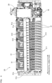
- the configuration of the ink supplier 1 for supplying ink to the plurality of heads 21 of the head unit 20 will be described next by referring to Fig. 2 .
- the head unit 20 includes the plurality of heads 21 aligned in a horizontal direction (a direction perpendicular to the plane of paper of Fig. 1 ).
- heads 21 indicated by dashed lines connected to a collection reservoir 23 are the same as heads 21 indicated by solid lines connected to a supply reservoir 22. In terms of the layout of the drawing, these heads 21 are illustrated twice.
- the ink supplier 1 includes the supply reservoir 22 and the collection reservoir 23 of the head unit 20, a drum tank 31, and a buffer tank 32 that function as storages of the ink.
- the ink supplier 1 includes a first transport unit 41, a second transport unit 42, a third transport unit 43, and a fourth transport unit 44 that function as means of transporting the ink between corresponding storages.
- the head unit 20 includes the plurality of heads 21, the supply reservoir 22, and the collection reservoir 23.
- Each of the heads 21 has a plurality of ejection nozzles provided at a surface of the bottom of the head 21 for ejecting the ink to the printing medium M.
- the supply reservoir 22 is an ink storage storing the ink to be supplied to the head 21.
- the supply reservoir 22 includes a first horizontal reservoir 51 and a first vertical reservoir 52.
- the first vertical reservoir 52 is a cylindrical storage with a covered top and a closed bottom.
- the first vertical reservoir 52 is larger in the top-bottom direction than the first horizontal reservoir 51.
- the first vertical reservoir 52 has a side surface where a first opening 520 directly communicating with the one end of the first horizontal reservoir 51 is provided.
- the second horizontal reservoir 61 is a cylindrical storage extending substantially horizontally in the direction of alignment of the plurality of heads 21.
- the second horizontal reservoir 61 has one end communicably connected to the second vertical reservoir 62.
- the second horizontal reservoir 61 is closed at the other end.
- the second horizontal reservoir 61 has a bottom provided with a plurality of collection ports 610 forming communication between the inside and outside of the second horizontal reservoir 61 in the top-bottom direction.
- Each of the collection ports 610 is communicably connected through a collection pipe 212 to the head 21 arranged below the collection port 610.
- a circulation path for the ink is formed by the buffer tank 32, the second transport unit 42, the collection reservoir 23, the third transport unit 43, the supply reservoir 22, and the fourth transport unit 44. Transporting the ink simultaneously through the second transport unit 42, the third transport unit 43, and the fourth transport unit 44 generates a flow of the ink flowing from the buffer tank 32 and returning to the buffer tank 32 through the second transport unit 42, the collection reservoir 23, the third transport unit 43, the supply reservoir 22, and the fourth transport unit 44.
- This ink circulation path is called an "out-of-head-unit circulation.”
- the supply port 510 provided at the bottom surface of the first horizontal reservoir 51 includes a first cylindrical part 510a penetrating the bottom surface of the first horizontal reservoir 51 from top to bottom to form communication between the inside and outside of the first horizontal reservoir 51.
- the first cylindrical part 510a has an upper end located above the bottom surface (inner surface) of the first horizontal reservoir 51.
- the first cylindrical part 510a has a lower end located outside the first horizontal reservoir 51 and communicably connected to the supply pipe 211 coupled the head 21.
- each of the first horizontal reservoir 51, the first vertical reservoir 52, the second horizontal reservoir 61, and the second vertical reservoir 62 has a shape tilted toward the lowermost point at the corresponding bottom surface.
- the precipitates P gather at the lowermost point at each bottom surface.
- the first horizontal reservoir 51 includes a first discharge port 81 penetrating the bottom surface from top to bottom in the vicinity of the other end 51b as the lowermost point at the bottom surface.
- the first vertical reservoir 52 includes a second discharge port 82 penetrating the bottom surface from top to bottom in the vicinity of the end thereof adjacent to the first opening 520 as the lowermost point at the bottom surface.
- the second horizontal reservoir 61 includes a third discharge port 83 penetrating the bottom surface from top to bottom in the vicinity of the other end 61b as the lowermost point at the bottom surface.
- the second vertical reservoir 62 includes a fourth discharge port 84 penetrating the bottom surface from top to bottom in the vicinity of the end thereof adjacent to the second opening 620 as the lowermost point at the bottom surface.
- the discharge port for discharge of a precipitate is provided in the vicinity of the lowermost point at each of the bottom surfaces where the precipitate gathers.
- the ink supplier 1 includes the discharge unit 70 for discharging a precipitate accumulated in the first horizontal reservoir 51, the first vertical reservoir 52, the second horizontal reservoir 61, and the second vertical reservoir 62.
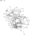
- the discharge unit 70 includes a first discharge pipe 71, a second discharge pipe 72, a first solenoid valve 73, a second solenoid valve 74, a third discharge pipe 75, a discharge pump 76, a drain exit 77, and a drip receiver 78.
- the discharge pump 76 is a so-called tube pump that squeezes a flexible pipe with a roller to generate a flow of a fluid in the pipe. Even if ink flowing in the pipe contains a precipitate, using such a tube pump as the discharge pump 76 makes it possible to deliver the ink together with the precipitate without causing operation failure.
- the discharge pump 76 is attached to a part of the pipe section 754 of the third discharge pipe 75 closer to the outlet 753 than the Y-shape branch. By doing so, driving the discharge pump 76 generates a flow of the ink from the first inlet 751 toward the outlet 753 and a flow of the ink from the second inlet 752 toward the outlet 753 in the third discharge pipe 75.
- the outlet 753 of the third discharge pipe 75 is connected to the drain exit 77.
- the drain exit 77 is configured in such a manner as to discharge the ink downward.
- the drip receiver 78 of a dish shape is provided under the drain exit 77.
- the drip receiver 78 is moved by a drip receiver moving mechanism 780 between a drip receiving position directly under the drain exit 77 (a position in Fig. 9 ) and a retreat position not overlapping the drain exit 77 one above the other (not shown in the drawings).
- An air cylinder is used as the drip receiver moving mechanism 780, for example.
- the discharge pump 76 is driven while the first solenoid valve 73 is opened. Opening the first solenoid valve 73 forms communication between the outlet 713 of the first discharge pipe 71 and the first inlet 751 of the third discharge pipe 75 through the first solenoid valve 73. Driving the discharge pump 76 generates a flow of the ink from the first inlet 751 toward the outlet 753 in the third discharge pipe 75. By doing so, a flow of a fluid from the first inlet 711 and a flow of a fluid from the second inlet 712 toward the outlet 713 are generated in the first discharge pipe 71.
- the ink containing a precipitate is sucked through the first discharge port 81 of the first horizontal reservoir 51 connected to the first inlet 711 of the first discharge pipe 71 and through the third discharge port 83 of the second horizontal reservoir 61 connected to the second inlet 712 of the first discharge pipe 71, and is then discharged through the drain exit 77.
- the first solenoid valve 73 is closed. At this time, the discharge pump 76 may be stopped or may be kept driven.
- the discharge pump 76 is driven while the second solenoid valve 74 is opened. Opening the second solenoid valve 74 forms communication between the outlet 723 of the second discharge pipe 72 and the second inlet 752 of the third discharge pipe 75 through the second solenoid valve 74. Driving the discharge pump 76 generates a flow of the ink from the second inlet 752 toward the outlet 753 in the third discharge pipe 75. By doing so, a flow of a fluid from the first inlet 721 and a flow of a fluid from the second inlet 722 toward the outlet 723 are generated in the second discharge pipe 72.
- the ink containing a precipitate is sucked through the second discharge port 82 of the first vertical reservoir 52 connected to the first inlet 721 of the second discharge pipe 72 and through the fourth discharge port 84 of the second vertical reservoir 62 connected to the second inlet 722 of the second discharge pipe 72, and is then discharged through the drain exit 77.
- the second solenoid valve 74 is closed and the discharge pump 76 is stopped. The process is discharging the ink is performed in this way.
- the process of discharging the ink by the discharge unit 70 is performed when the printing process by the printing apparatus 9 stops.
- a cap to receive the discharged ink is arranged under the head unit 20, for example.
- the ink is ejected from the head 21 in a purge process, for example, or the process of discharging the ink is performed by the discharge unit 70.
- the drip receiver 78 is located at the retreat position to cause the ink discharged through the drain exit 77 to move toward the cap.
- the head unit 20 and the cap are moved away from each other and the head unit 20 is located above the printing medium M.
- the drip receiver 78 is located at the drip receiving position.
- the one ends 51a and 61a of the horizontal reservoirs 51 and 61 directly communicate with the vertical reservoirs 52 and 62 through the openings 520 and 620 respectively.
- the present invention is not limited to this configuration.
- the one ends 51a and 61a of the horizontal reservoirs 51 and 61 may form indirect communications through connection pipes, for example.
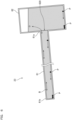
- Fig. 11 is a conceptual view showing the behaviors of air bubbles and precipitates in a supply reservoir 22M according to a modification.
- one end 51Ma of a first horizontal reservoir 51M and a first opening 520M of a first vertical reservoir 52M are communicably connected to each other through a connection pipe 53M.
- a top surface of the first horizontal reservoir 51M and a top surface of the connection pipe 53M are continuous with each other while extending at the same angle of tilt from the other end 51Mb of the first horizontal reservoir 51M to the first opening 520M.
- the top surface from the other end 51Mb of the first horizontal reservoir 51M to the first opening 520M is tilted from the horizontal direction at a predetermined angle of tilt in such a manner as to extend upward from the other end 51Mb toward the one end 51Ma of the first horizontal reservoir 51M.
- first horizontal reservoir 51M and the first vertical reservoir 52M are communicably connected to each other indirectly through the connection pipe 53M, air bubbles in the first horizontal reservoir 51M are still allowed to move along the top surface of the first horizontal reservoir 51M and the top surface of the connection pipe 53M into the first vertical reservoir 52M through the first opening 520.
- the respective bottom surfaces of the vertical reservoirs 52 and 62 have planar shapes tilted from the horizontal direction.
- the lowermost points at the bottom surfaces are located at ends of the bottom surfaces of the vertical reservoirs 52 and 62, and the discharge ports 82 and 84 are provided in the vicinity of the end of the vertical reservoir 52 and in the vicinity of the end of the vertical reservoir 62 respectively.
- the bottom surfaces of the vertical reservoirs 52 and 62 are not limited to planar shapes.
- each of the bottom surfaces may have a funnel shape pointed downward further at a position closer to the center to locate a lowermost point at the center of the bottom surface, and a discharge port may be provided at the center of the bottom surface.
- the ink used in the above-described preferred embodiment is ink of a watercolor pigment type.
- the ink may be oil-based ink or dye-based ink.
- the printing apparatus 9 includes the coating processor 92 and the drying processor 94.
- the present invention is not limited to this configuration.
- the ink supplier of the present invention may be used in a printing apparatus to perform only the printing process.
Landscapes
- Ink Jet (AREA)
Claims (8)
- Tintenzuführung (1), die einer Vielzahl von Köpfen (21) in einer Tintenstrahldruckvorrichtung (9) Tinte zuführt, umfassend:einen Zuführbehälter (22), der die Tinte speichert, die der Vielzahl von Köpfen (21) zugeführt werden soll; undein Auslassrohr (71, 72, 73) mit einer Pumpe (76), die zum Auslassen der Tinte aus dem Zuführbehälter (22) verwendet wird,wobei der Zuführbehälter (22) umfasst:einen ersten horizontalen Behälter (51) mit einer zylindrischen Form, der sich in einer Ausrichtungsrichtung der Vielzahl von Köpfen (21) erstreckt und eine Vielzahl von Zuführöffnungen (510) aufweist, die jeweils mit einem der Vielzahl von Köpfen (21) in Verbindung stehen; undeinen ersten vertikalen Behälter (52) mit einer Seitenfläche, die mit einer ersten Öffnung (520) vorgesehen ist, die direkt oder indirekt mit einem Ende (51a) des ersten horizontalen Behälters (51) in Verbindung steht, und mit einer zylindrischen Form mit einem geschlossenen Boden, der in einer Richtung von oben nach unten größer ist als der erste horizontale Behälter (51),wobei der erste horizontale Behälter (51) eine Bodenfläche aufweist, die aus einer horizontalen Richtung mit einem Neigungswinkel von 0,3° oder mehr derart geneigt ist, dass sie sich von dem einen Ende (51a) zu dem anderen Ende (51b) hin nach unten erstreckt,wobei der erste horizontale Behälter (51) eine erste Auslassöffnung (81) umfasst, die an einem unteren Abschnitt des ersten horizontalen Behälters (51) an dem anderen Ende (51b) vorgesehen und mit dem Auslassrohr (71, 72, 73) kommunizierend verbunden ist.
- Tintenzuführung (1) nach Anspruch 1, wobei
der erste vertikale Behälter (52) eine zweite Auslassöffnung (82) aufweist, die an einem untersten Punkt an einem unteren Abschnitt des ersten vertikalen Behälters (52) vorgesehen und mit dem Auslassrohr (71, 72, 73) verbunden ist. - Tintenzuführung (1) nach Anspruch 2, wobeider erste vertikale Behälter (52) eine ebene Bodenfläche aufweist,die Bodenfläche des ersten vertikalen Behälters (52) aus der horizontalen Richtung mit einem Neigungswinkel von 0,3° oder mehr derart geneigt ist, dass sie sich mit dem Abstand von dem ersten horizontalen Behälter (51) nach oben erstreckt, unddie zweite Auslassöffnung (82) an einem unteren Abschnitt des ersten vertikalen Behälters (52) an einem Ende neben dem ersten horizontalen Behälter (51) vorgesehen ist.
- Tintenzuführung (1) nach Anspruch 1, die einer Vielzahl von Köpfen (21) in einer Tintenstrahldruckvorrichtung Tinte zuführt, ferner umfassend:einen Sammelbehälter (23), der die von der Vielzahl von Köpfen (21) gesammelte Tinte speichert, wobeider Sammelbehälter (23) umfasst:einen zweiten horizontalen Behälter (61) mit einer zylindrischen Form, der sich in der Ausrichtungsrichtung der Vielzahl von Köpfen (21) erstreckt und eine Vielzahl von Sammelöffnungen (610) aufweist, die jeweils mit einem der Vielzahl von Köpfen (21) in Verbindung stehen; undeinen zweiten vertikalen Behälter (62) mit einer Seitenfläche, die mit einer zweiten Öffnung (620) vorgesehen ist, die direkt oder indirekt mit einem Ende (61a) des zweiten horizontalen Behälters (61) in Verbindung steht, und mit einer zylindrischen Form mit einem geschlossenen Boden, der in der Richtung von oben nach unten größer ist als der zweite horizontale Behälter (61),wobei der zweite horizontale Behälter (61) eine Bodenfläche aufweist, die aus der horizontalen Richtung in einem Neigungswinkel von 0,3° oder mehr derart geneigt ist, dass sie sich von dem einen Ende (61a) zu dem anderen Ende (61b) hin nach unten erstreckt, undder zweite horizontale Behälter (61) eine dritte Auslassöffnung (83) aufweist, die an einem unteren Abschnitt des zweiten horizontalen Behälters (61) an dem anderen Ende (61a) vorgesehen und mit dem Auslassrohr (71, 72, 73) kommunizierend verbunden ist.
- Tintenzuführung (1) nach Anspruch 4, wobei
der zweite vertikale Behälter (62) eine vierte Auslassöffnung (84) aufweist, die an einem untersten Punkt an einem unteren Abschnitt des zweiten vertikalen Behälters (62) vorgesehen ist und mit dem Auslassrohr (71, 72, 73) kommunizierend verbunden ist. - Tintenzuführung (1) nach Anspruch 5, wobeider zweite vertikale Behälter (62) eine ebene Bodenfläche aufweist,die Bodenfläche des zweiten vertikalen Behälters (62) aus der horizontalen Richtung mit einem Neigungswinkel von 0,3° oder mehr derart geneigt ist, dass sie sich mit Abstand von dem zweiten horizontalen Behälter (61) nach oben erstreckt, unddie vierte Auslassöffnung (84) an einem unteren Abschnitt des zweiten vertikalen Behälters (62) an einem Ende neben dem zweiten horizontalen Behälter (61) vorgesehen ist.
- Tintenzuführung (1) nach einem der Ansprüche 4 bis 6, wobeijede der Vielzahl von Sammelöffnungen (610) einen zweiten zylindrischen Teil (610a) aufweist, der eine Verbindung herstellt, indem er die Bodenfläche des zweiten horizontalen Behälters (61) von oben nach unten durchdringt,der zweite zylindrische Teil (610a) ein oberes Ende aufweist, das sich über der Bodenfläche des zweiten horizontalen Behälters (61) befindet, undder zweite zylindrische Teil (610a) ein unteres Ende aufweist, das mit einem an den Kopf (21) gekoppelten Rohr in Verbindung steht.
- Tintenzuführung (1) nach einem der Ansprüche 1 bis 7, wobeijede der Vielzahl von Zuführöffnungen (510) einen ersten zylindrischen Teil (510a) aufweist, der eine Verbindung bildet, indem er die Bodenfläche des ersten horizontalen Behälters (51) von oben nach unten durchdringt,der erste zylindrische Teil (510a) ein oberes Ende aufweist, das sich über der Bodenfläche des ersten horizontalen Behälters (51) befindet, undder erste zylindrische Teil (510) ein unteres Ende aufweist, das mit einem an den Kopf (21) gekoppelten Rohr in Verbindung steht.
Applications Claiming Priority (1)
| Application Number | Priority Date | Filing Date | Title |
|---|---|---|---|
| JP2022189436A JP2024077374A (ja) | 2022-11-28 | 2022-11-28 | インク供給装置 |
Publications (2)
| Publication Number | Publication Date |
|---|---|
| EP4375072A1 EP4375072A1 (de) | 2024-05-29 |
| EP4375072B1 true EP4375072B1 (de) | 2025-04-16 |
Family
ID=88969754
Family Applications (1)
| Application Number | Title | Priority Date | Filing Date |
|---|---|---|---|
| EP23212077.4A Active EP4375072B1 (de) | 2022-11-28 | 2023-11-24 | Tintenliefergerät |
Country Status (3)
| Country | Link |
|---|---|
| US (1) | US12558905B2 (de) |
| EP (1) | EP4375072B1 (de) |
| JP (1) | JP2024077374A (de) |
Family Cites Families (7)
| Publication number | Priority date | Publication date | Assignee | Title |
|---|---|---|---|---|
| JP2009051046A (ja) * | 2007-08-24 | 2009-03-12 | Canon Inc | インクジェット記録ヘッド及び気泡除去方法 |
| FR2952584B1 (fr) * | 2009-11-13 | 2016-01-22 | Mgi France | Nourrice de distribution d'encre pour tete d'impression a jet d'encre et procede de fabrication de la nourrice |
| EP2803487B1 (de) * | 2012-01-11 | 2018-06-20 | Seiren Co., Ltd. | Tintenstrahldruckvorrichtung |
| US10894420B2 (en) | 2018-04-11 | 2021-01-19 | Canon Kabushiki Kaisha | Ejection-material injecting method, ejection-material ejection apparatus, and imprinting apparatus |
| JP7277127B2 (ja) * | 2018-04-11 | 2023-05-18 | キヤノン株式会社 | 吐出材充填方法、吐出材吐出装置、およびインプリント装置 |
| KR102139137B1 (ko) * | 2018-12-10 | 2020-07-29 | 주식회사 고산테크 | 잉크젯 프린터의 잉크 저장장치 |
| JP7508319B2 (ja) | 2020-09-23 | 2024-07-01 | 株式会社Screenホールディングス | 印刷装置 |
-
2022
- 2022-11-28 JP JP2022189436A patent/JP2024077374A/ja active Pending
-
2023
- 2023-11-24 EP EP23212077.4A patent/EP4375072B1/de active Active
- 2023-11-28 US US18/521,430 patent/US12558905B2/en active Active
Also Published As
| Publication number | Publication date |
|---|---|
| US12558905B2 (en) | 2026-02-24 |
| EP4375072A1 (de) | 2024-05-29 |
| JP2024077374A (ja) | 2024-06-07 |
| US20240173995A1 (en) | 2024-05-30 |
Similar Documents
| Publication | Publication Date | Title |
|---|---|---|
| US9724930B2 (en) | Liquid ejecting apparatus | |
| CN101638006B (zh) | 液体供给装置、液体喷出装置和液体喷出装置的控制方法 | |
| CN103826861B (zh) | 液体喷出装置及液体移送方法 | |
| US11964489B2 (en) | Inkjet recording apparatus | |
| US20190224982A1 (en) | Liquid discharge unit and image forming apparatus | |
| EP2436522B1 (de) | Bilderzeugungsvorrichtung | |
| JP6544057B2 (ja) | 液体攪拌装置及び画像形成装置 | |
| JP6929095B2 (ja) | インクジェット記録装置 | |
| EP4375072B1 (de) | Tintenliefergerät | |
| EP4375073A1 (de) | Tintenliefergerät | |
| JP7034005B2 (ja) | インクジェット印刷装置 | |
| US11040538B2 (en) | Inkjet printer and maintenance method | |
| US12179495B2 (en) | Printing apparatus and ink feeding method in printing apparatus | |
| CN103085493B (zh) | 液体排出装置以及液体循环方法 | |
| JP7666181B2 (ja) | 液体吐出装置 | |
| EP4173830B1 (de) | Bilderzeugungsvorrichtung | |
| JP6293546B2 (ja) | 液体供給装置および液体吐出装置 | |
| US20250296347A1 (en) | Ink supplier | |
| JP7785547B2 (ja) | 液体供給装置、液体吐出装置及び液体供給方法 | |
| JP2021112825A (ja) | 記録液供給装置および画像形成装置 | |
| JP7459518B2 (ja) | 記録液供給装置および画像形成装置 | |
| EP4501650A1 (de) | Tintenstrahlaufzeichnungsvorrichtung | |
| JP4613988B2 (ja) | 液体供給装置、液体吐出装置、及び液体吐出装置の制御方法 | |
| JP2021112826A (ja) | 記録液供給装置および画像形成装置 | |
| JP2025049948A (ja) | インク供給装置 |
Legal Events
| Date | Code | Title | Description |
|---|---|---|---|
| PUAI | Public reference made under article 153(3) epc to a published international application that has entered the european phase |
Free format text: ORIGINAL CODE: 0009012 |
|
| STAA | Information on the status of an ep patent application or granted ep patent |
Free format text: STATUS: THE APPLICATION HAS BEEN PUBLISHED |
|
| AK | Designated contracting states |
Kind code of ref document: A1 Designated state(s): AL AT BE BG CH CY CZ DE DK EE ES FI FR GB GR HR HU IE IS IT LI LT LU LV MC ME MK MT NL NO PL PT RO RS SE SI SK SM TR |
|
| STAA | Information on the status of an ep patent application or granted ep patent |
Free format text: STATUS: REQUEST FOR EXAMINATION WAS MADE |
|
| 17P | Request for examination filed |
Effective date: 20240723 |
|
| RBV | Designated contracting states (corrected) |
Designated state(s): AL AT BE BG CH CY CZ DE DK EE ES FI FR GB GR HR HU IE IS IT LI LT LU LV MC ME MK MT NL NO PL PT RO RS SE SI SK SM TR |
|
| GRAP | Despatch of communication of intention to grant a patent |
Free format text: ORIGINAL CODE: EPIDOSNIGR1 |
|
| STAA | Information on the status of an ep patent application or granted ep patent |
Free format text: STATUS: GRANT OF PATENT IS INTENDED |
|
| INTG | Intention to grant announced |
Effective date: 20241128 |
|
| GRAS | Grant fee paid |
Free format text: ORIGINAL CODE: EPIDOSNIGR3 |
|
| GRAA | (expected) grant |
Free format text: ORIGINAL CODE: 0009210 |
|
| STAA | Information on the status of an ep patent application or granted ep patent |
Free format text: STATUS: THE PATENT HAS BEEN GRANTED |
|
| AK | Designated contracting states |
Kind code of ref document: B1 Designated state(s): AL AT BE BG CH CY CZ DE DK EE ES FI FR GB GR HR HU IE IS IT LI LT LU LV MC ME MK MT NL NO PL PT RO RS SE SI SK SM TR |
|
| REG | Reference to a national code |
Ref country code: GB Ref legal event code: FG4D |
|
| REG | Reference to a national code |
Ref country code: CH Ref legal event code: EP Ref country code: DE Ref legal event code: R096 Ref document number: 602023002964 Country of ref document: DE |
|
| REG | Reference to a national code |
Ref country code: IE Ref legal event code: FG4D |
|
| P01 | Opt-out of the competence of the unified patent court (upc) registered |
Free format text: CASE NUMBER: APP_16588/2025 Effective date: 20250404 |
|
| REG | Reference to a national code |
Ref country code: NL Ref legal event code: MP Effective date: 20250416 |
|
| PG25 | Lapsed in a contracting state [announced via postgrant information from national office to epo] |
Ref country code: NL Free format text: LAPSE BECAUSE OF FAILURE TO SUBMIT A TRANSLATION OF THE DESCRIPTION OR TO PAY THE FEE WITHIN THE PRESCRIBED TIME-LIMIT Effective date: 20250416 |
|
| REG | Reference to a national code |
Ref country code: AT Ref legal event code: MK05 Ref document number: 1785334 Country of ref document: AT Kind code of ref document: T Effective date: 20250416 |
|
| PG25 | Lapsed in a contracting state [announced via postgrant information from national office to epo] |
Ref country code: PT Free format text: LAPSE BECAUSE OF FAILURE TO SUBMIT A TRANSLATION OF THE DESCRIPTION OR TO PAY THE FEE WITHIN THE PRESCRIBED TIME-LIMIT Effective date: 20250818 Ref country code: ES Free format text: LAPSE BECAUSE OF FAILURE TO SUBMIT A TRANSLATION OF THE DESCRIPTION OR TO PAY THE FEE WITHIN THE PRESCRIBED TIME-LIMIT Effective date: 20250416 Ref country code: FI Free format text: LAPSE BECAUSE OF FAILURE TO SUBMIT A TRANSLATION OF THE DESCRIPTION OR TO PAY THE FEE WITHIN THE PRESCRIBED TIME-LIMIT Effective date: 20250416 |
|
| REG | Reference to a national code |
Ref country code: LT Ref legal event code: MG9D |
|
| PG25 | Lapsed in a contracting state [announced via postgrant information from national office to epo] |
Ref country code: NO Free format text: LAPSE BECAUSE OF FAILURE TO SUBMIT A TRANSLATION OF THE DESCRIPTION OR TO PAY THE FEE WITHIN THE PRESCRIBED TIME-LIMIT Effective date: 20250716 Ref country code: GR Free format text: LAPSE BECAUSE OF FAILURE TO SUBMIT A TRANSLATION OF THE DESCRIPTION OR TO PAY THE FEE WITHIN THE PRESCRIBED TIME-LIMIT Effective date: 20250717 |
|
| PG25 | Lapsed in a contracting state [announced via postgrant information from national office to epo] |
Ref country code: PL Free format text: LAPSE BECAUSE OF FAILURE TO SUBMIT A TRANSLATION OF THE DESCRIPTION OR TO PAY THE FEE WITHIN THE PRESCRIBED TIME-LIMIT Effective date: 20250416 |
|
| PG25 | Lapsed in a contracting state [announced via postgrant information from national office to epo] |
Ref country code: BG Free format text: LAPSE BECAUSE OF FAILURE TO SUBMIT A TRANSLATION OF THE DESCRIPTION OR TO PAY THE FEE WITHIN THE PRESCRIBED TIME-LIMIT Effective date: 20250416 |
|
| PG25 | Lapsed in a contracting state [announced via postgrant information from national office to epo] |
Ref country code: HR Free format text: LAPSE BECAUSE OF FAILURE TO SUBMIT A TRANSLATION OF THE DESCRIPTION OR TO PAY THE FEE WITHIN THE PRESCRIBED TIME-LIMIT Effective date: 20250416 |
|
| PG25 | Lapsed in a contracting state [announced via postgrant information from national office to epo] |
Ref country code: AT Free format text: LAPSE BECAUSE OF FAILURE TO SUBMIT A TRANSLATION OF THE DESCRIPTION OR TO PAY THE FEE WITHIN THE PRESCRIBED TIME-LIMIT Effective date: 20250416 |
|
| PG25 | Lapsed in a contracting state [announced via postgrant information from national office to epo] |
Ref country code: RS Free format text: LAPSE BECAUSE OF FAILURE TO SUBMIT A TRANSLATION OF THE DESCRIPTION OR TO PAY THE FEE WITHIN THE PRESCRIBED TIME-LIMIT Effective date: 20250716 |
|
| PG25 | Lapsed in a contracting state [announced via postgrant information from national office to epo] |
Ref country code: IS Free format text: LAPSE BECAUSE OF FAILURE TO SUBMIT A TRANSLATION OF THE DESCRIPTION OR TO PAY THE FEE WITHIN THE PRESCRIBED TIME-LIMIT Effective date: 20250816 |
|
| PG25 | Lapsed in a contracting state [announced via postgrant information from national office to epo] |
Ref country code: LV Free format text: LAPSE BECAUSE OF FAILURE TO SUBMIT A TRANSLATION OF THE DESCRIPTION OR TO PAY THE FEE WITHIN THE PRESCRIBED TIME-LIMIT Effective date: 20250416 |
|
| PGFP | Annual fee paid to national office [announced via postgrant information from national office to epo] |
Ref country code: DE Payment date: 20251129 Year of fee payment: 3 |
|
| PG25 | Lapsed in a contracting state [announced via postgrant information from national office to epo] |
Ref country code: DK Free format text: LAPSE BECAUSE OF FAILURE TO SUBMIT A TRANSLATION OF THE DESCRIPTION OR TO PAY THE FEE WITHIN THE PRESCRIBED TIME-LIMIT Effective date: 20250416 Ref country code: SM Free format text: LAPSE BECAUSE OF FAILURE TO SUBMIT A TRANSLATION OF THE DESCRIPTION OR TO PAY THE FEE WITHIN THE PRESCRIBED TIME-LIMIT Effective date: 20250416 |
|
| PGFP | Annual fee paid to national office [announced via postgrant information from national office to epo] |
Ref country code: FR Payment date: 20251129 Year of fee payment: 3 |
|
| REG | Reference to a national code |
Ref country code: DE Ref legal event code: R097 Ref document number: 602023002964 Country of ref document: DE |
|
| PG25 | Lapsed in a contracting state [announced via postgrant information from national office to epo] |
Ref country code: CZ Free format text: LAPSE BECAUSE OF FAILURE TO SUBMIT A TRANSLATION OF THE DESCRIPTION OR TO PAY THE FEE WITHIN THE PRESCRIBED TIME-LIMIT Effective date: 20250416 |
|
| PG25 | Lapsed in a contracting state [announced via postgrant information from national office to epo] |
Ref country code: EE Free format text: LAPSE BECAUSE OF FAILURE TO SUBMIT A TRANSLATION OF THE DESCRIPTION OR TO PAY THE FEE WITHIN THE PRESCRIBED TIME-LIMIT Effective date: 20250416 |
|
| PG25 | Lapsed in a contracting state [announced via postgrant information from national office to epo] |
Ref country code: SK Free format text: LAPSE BECAUSE OF FAILURE TO SUBMIT A TRANSLATION OF THE DESCRIPTION OR TO PAY THE FEE WITHIN THE PRESCRIBED TIME-LIMIT Effective date: 20250416 |
|
| PG25 | Lapsed in a contracting state [announced via postgrant information from national office to epo] |
Ref country code: IT Free format text: LAPSE BECAUSE OF FAILURE TO SUBMIT A TRANSLATION OF THE DESCRIPTION OR TO PAY THE FEE WITHIN THE PRESCRIBED TIME-LIMIT Effective date: 20250416 |
|
| PLBE | No opposition filed within time limit |
Free format text: ORIGINAL CODE: 0009261 |
|
| STAA | Information on the status of an ep patent application or granted ep patent |
Free format text: STATUS: NO OPPOSITION FILED WITHIN TIME LIMIT |
|
| REG | Reference to a national code |
Ref country code: CH Ref legal event code: L10 Free format text: ST27 STATUS EVENT CODE: U-0-0-L10-L00 (AS PROVIDED BY THE NATIONAL OFFICE) Effective date: 20260225 |
|
| PG25 | Lapsed in a contracting state [announced via postgrant information from national office to epo] |
Ref country code: RO Free format text: LAPSE BECAUSE OF FAILURE TO SUBMIT A TRANSLATION OF THE DESCRIPTION OR TO PAY THE FEE WITHIN THE PRESCRIBED TIME-LIMIT Effective date: 20250416 |
|
| 26N | No opposition filed |
Effective date: 20260119 |