EP4374072B1 - Druckpackung für hubkolbenverdichter mit puffergassperre - Google Patents
Druckpackung für hubkolbenverdichter mit puffergassperre Download PDFInfo
- Publication number
- EP4374072B1 EP4374072B1 EP23725184.8A EP23725184A EP4374072B1 EP 4374072 B1 EP4374072 B1 EP 4374072B1 EP 23725184 A EP23725184 A EP 23725184A EP 4374072 B1 EP4374072 B1 EP 4374072B1
- Authority
- EP
- European Patent Office
- Prior art keywords
- pressure
- buffer gas
- line
- gas
- packing
- Prior art date
- Legal status (The legal status is an assumption and is not a legal conclusion. Google has not performed a legal analysis and makes no representation as to the accuracy of the status listed.)
- Active
Links
Images


Classifications
-
- F—MECHANICAL ENGINEERING; LIGHTING; HEATING; WEAPONS; BLASTING
- F04—POSITIVE - DISPLACEMENT MACHINES FOR LIQUIDS; PUMPS FOR LIQUIDS OR ELASTIC FLUIDS
- F04B—POSITIVE-DISPLACEMENT MACHINES FOR LIQUIDS; PUMPS
- F04B39/00—Component parts, details, or accessories, of pumps or pumping systems specially adapted for elastic fluids, not otherwise provided for in, or of interest apart from, groups F04B25/00 - F04B37/00
- F04B39/12—Casings; Cylinders; Cylinder heads; Fluid connections
- F04B39/123—Fluid connections
-
- F—MECHANICAL ENGINEERING; LIGHTING; HEATING; WEAPONS; BLASTING
- F04—POSITIVE - DISPLACEMENT MACHINES FOR LIQUIDS; PUMPS FOR LIQUIDS OR ELASTIC FLUIDS
- F04B—POSITIVE-DISPLACEMENT MACHINES FOR LIQUIDS; PUMPS
- F04B53/00—Component parts, details or accessories not provided for in, or of interest apart from, groups F04B1/00 - F04B23/00 or F04B39/00 - F04B47/00
- F04B53/02—Packing the free space between cylinders and pistons
-
- F—MECHANICAL ENGINEERING; LIGHTING; HEATING; WEAPONS; BLASTING
- F04—POSITIVE - DISPLACEMENT MACHINES FOR LIQUIDS; PUMPS FOR LIQUIDS OR ELASTIC FLUIDS
- F04B—POSITIVE-DISPLACEMENT MACHINES FOR LIQUIDS; PUMPS
- F04B39/00—Component parts, details, or accessories, of pumps or pumping systems specially adapted for elastic fluids, not otherwise provided for in, or of interest apart from, groups F04B25/00 - F04B37/00
- F04B39/04—Measures to avoid lubricant contaminating the pumped fluid
- F04B39/041—Measures to avoid lubricant contaminating the pumped fluid sealing for a reciprocating rod
-
- F—MECHANICAL ENGINEERING; LIGHTING; HEATING; WEAPONS; BLASTING
- F04—POSITIVE - DISPLACEMENT MACHINES FOR LIQUIDS; PUMPS FOR LIQUIDS OR ELASTIC FLUIDS
- F04B—POSITIVE-DISPLACEMENT MACHINES FOR LIQUIDS; PUMPS
- F04B49/00—Control, e.g. of pump delivery, or pump pressure of, or safety measures for, machines, pumps, or pumping installations, not otherwise provided for, or of interest apart from, groups F04B1/00 - F04B47/00
- F04B49/10—Other safety measures
-
- F—MECHANICAL ENGINEERING; LIGHTING; HEATING; WEAPONS; BLASTING
- F04—POSITIVE - DISPLACEMENT MACHINES FOR LIQUIDS; PUMPS FOR LIQUIDS OR ELASTIC FLUIDS
- F04B—POSITIVE-DISPLACEMENT MACHINES FOR LIQUIDS; PUMPS
- F04B49/00—Control, e.g. of pump delivery, or pump pressure of, or safety measures for, machines, pumps, or pumping installations, not otherwise provided for, or of interest apart from, groups F04B1/00 - F04B47/00
- F04B49/22—Control, e.g. of pump delivery, or pump pressure of, or safety measures for, machines, pumps, or pumping installations, not otherwise provided for, or of interest apart from, groups F04B1/00 - F04B47/00 by means of valves
-
- F—MECHANICAL ENGINEERING; LIGHTING; HEATING; WEAPONS; BLASTING
- F04—POSITIVE - DISPLACEMENT MACHINES FOR LIQUIDS; PUMPS FOR LIQUIDS OR ELASTIC FLUIDS
- F04B—POSITIVE-DISPLACEMENT MACHINES FOR LIQUIDS; PUMPS
- F04B53/00—Component parts, details or accessories not provided for in, or of interest apart from, groups F04B1/00 - F04B23/00 or F04B39/00 - F04B47/00
- F04B53/06—Venting
-
- F—MECHANICAL ENGINEERING; LIGHTING; HEATING; WEAPONS; BLASTING
- F04—POSITIVE - DISPLACEMENT MACHINES FOR LIQUIDS; PUMPS FOR LIQUIDS OR ELASTIC FLUIDS
- F04B—POSITIVE-DISPLACEMENT MACHINES FOR LIQUIDS; PUMPS
- F04B53/00—Component parts, details or accessories not provided for in, or of interest apart from, groups F04B1/00 - F04B23/00 or F04B39/00 - F04B47/00
- F04B53/16—Casings; Cylinders; Cylinder liners or heads; Fluid connections
- F04B53/162—Adaptations of cylinders
- F04B53/164—Stoffing boxes
Definitions
- the present invention pertains to a pressure packing for a reciprocating piston compressor having a buffer gas barrier at a low-pressure side of the pressure packing and a number of sealing rings at an opposite high-pressure side of the pressure packing, whereas a vent volume is provided in the pressure packing between the buffer gas barrier and the last sealing ring before the buffer gas barrier with a vent line being connected to the vent volume, whereas a buffer gas volume is provided in the buffer gas barrier that is connected to a buffer gas feeding line, whereas, during operation of the pressure packing, a buffer gas with buffer gas pressure is supplied into the buffer gas volume via the buffer gas feeding line with the buffer gas pressure being higher than the vent pressure in the vent volume.
- the invention pertains also to a method for operating such a pressure packing for a reciprocating piston compressor and to a reciprocating piston compressor with such a pressure packing.
- a reciprocating piston compressor for compressing a process gas are well known and are used in many applications and for different process gases.
- a reciprocating piston compressor comprises at least one cylinder with at least one suction valve and at least one discharge valve for the process gas exchange.
- a piston reciprocates back and forth driven by a piston rod.
- a pressure packing surrounds the piston rod to seal the gas in the cylinder.
- a pressure packing comprises a packing case made up of several adjacent (in the axial direction of the packing case / piston rod) packing cups with sealing rings and/or wiper rings being arranged in the cups.
- a reciprocating piston compressor with a pressure packing is known from US 2018/0066802 A1 or EP 2 905 468 A1 , for example.
- the piston rod is connected to a crosshead which in turn is connected to a crank of a crankshaft.
- the crosshead translates the rotating movement of the crank into the reciprocating movement of the piston rod.
- the crank shaft is located in a crankcase. Between the crankcase and the cylinder (or the pressure packing) there is often arranged a distance piece in which the piston rod and sometimes also the crosshead or at least a part of the crosshead reciprocates. Between the distance piece and the crank case there can also be arranged an additional partition packing around the piston rod.
- a process gas leakage through the pressure packing or around the pressure packing as the pressure packing is never absolutely gastight. Such a process gas leakage is undesirable, not only because of the resulting process gas loss.
- process gas leakage can be problematic, especially when toxic, hazardous, combustible or explosive process gas is used.
- vent line in the pressure packing which provides for connection from a location inside the pressure packing to a location on the exterior of the pressure packing. Connection of additional conduits to the external vent line exit from the pressure packing allows for directing the process gas leakage to a controlled point external to the compressor itself.
- the vent line is connected to a vent volume, e.g. arranged in a vent cup or between two adjacent sealing rings, in the pressure packing. Process gas leaking into the pressure packing is directed from the vent volume into the vent line.
- a vent line in the pressure packing does however not totally prevent process gas leakage, as gas leakage can also occur between adjacent cups or even around the pressure packing.
- pressurised buffer gas such as Nitrogen or any other inert or unproblematic gas
- the pressure of the buffer gas is set to be higher than the pressure of the process gas at the respective location, for example at the low-pressure side of the pressure packing.
- the buffer gas is fed between two adjacent sealing rings of the pressure packing and forms a gas barrier for the process gas in the pressure packing. In this case, only buffer gas exits the pressure packing. If a vent line is used in the pressure packing, the internal starting point of the vent line in the pressure packing is located between the sealing rings at the high-pressure side of the packing and the gas barrier. In this case, buffer gas would also be removed via the vent line.
- buffer gas could be used to form a gas barrier to reduce the risk of process gas leakage from the distance piece into the crankcase.
- a gas barrier in the pressure packing or partition packing does however not prevent process gas leakage between cups or around the packing itself. Therefore, it is sometimes also provided to purge the distance piece with purge gas.
- purge gas the same gas is usually used that is used as buffer gas. This means the purge gas is fed into the distance piece and a mixture of purge gas with any process gas leakage is drained from the distance piece.
- the purge panel comprises the necessary instrumentation, like valves, flow regulators, measurement instruments, etc., needed for providing the buffer gas. It is especially important to be able to control the pressure of the buffer gas, which has to be higher than the gas pressure of the gas to be sealed or has to be high enough to allow purging of the distance piece.
- the buffer gas pressure is at least 1 bar higher than the gas at the respective location of usage of the buffer gas. For certain locations, for example in the distance piece or the partition packing, the buffer gas pressure could be set statically to a certain pressure.
- a buffer gas in a pressure packing with a vent line requires however a dynamically changing buffer gas pressure as the pressure in the packing, and especially in the vent line, usually varies dynamically (depending on the backpressure existing in the vent line, for example if connected to a flare system for flaring leaking process gas). Therefore, the pressure in the vent line is often used as pilot pressure to control a pressure regulator in the purge panel to set the buffer gas pressure.
- vent line connected to the vent volume of the pressure packing would be routed through the panel itself in order to be able to use the vent line pressure as pilot pressure for the differential pressure regulator. It is also known to branch off a pilot line from the vent line and to lead the pilot line into the purge panel. This creates however several issues. On lubricated compressors, there is the necessity to install a liquid/gaseous separator for the vent line or pilot line between the compressor and the purge panel, causing extra cost. Another issue is the pressure drop in the vent line caused by flow of gas in the line. In operation of the compressor, the gas leakage from the pressure packing increases over time due to wear of the sealing rings in the packing.
- This variable (increasing) pressure drop means that the purge panel reads the wrong pilot pressure from the vent line for controlling the pressure regulator, and therefore the performance of the purge panel degrades over time. This can cause increased emissions of process gas from the compressor, which has to be avoided.
- a pressure packing as claimed in claim 1, with a sensing line that is connected at a first end to the vent volume in the pressure packing with an opposite second end of the sensing line being closed, so that there is no gas flow in the sensing line, and by connecting a pressure regulator to the buffer gas feeding line for setting the buffer gas pressure in the buffer gas feeding line, whereas, during operation of the pressure packing, the pressure in the sensing line is used as pilot pressure for the pressure regulator for setting the buffer gas pressure.
- the sensing line is completely separated from the vent line by which process gas leakage is carried away from the pressure packing.
- the buffer gas pressure is preferably set a given differential pressure higher than the pilot pressure (vent pressure).
- a corresponding method for operating a pressure packing is defined by claim 16.
- a differential pressure control valve with a pilot input is used as pressure regulator, whereas the sensing sense line is connected to the pilot pressure input of the differential pressure control valve.
- the sensing line is advantageously arranged in an upper part of the pressure packing. This, together with the fact that the sensing line is a static line without gas flow, reduces or even eliminates the amount of lubricant oil that can possibly be carried with the sensing line. Therefore, no liquid gas separator is required in the sensing line upstream of the pressure regulator, which reduces the overall costs and equipment complexity.
- a purge panel with an enclosure it is especially advantageous to provide a pneumatic booster relay outside of the enclosure with the sensing line being connected to a pilot port of the pneumatic booster relay. In that way it can be ensured that the process gas in the sensing line cannot leak into the enclosure in case of malfunction, which would be hazard.
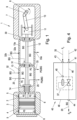
- Fig.1 shows a typical configuration of a reciprocating piston compressor 1 having one cylinder 2 arranged in a cylinder head 3.
- a piston 4 is reciprocally moved back and forth.
- the compressor 1 is a double-acting piston compressor with two compression volumes in the cylinder 2, one on each side of the piston 4.
- the compressor 1 could however also be a single-acting piston compressor.
- the reciprocating piston compressor 1 of Fig.1 has only one cylinder 2, but could of course have any number of cylinders required.
- the reciprocating piston compressor 1 could also be implemented as single-stage compressor or as multi-stage compressor. In a multi-stage compressor, the compressed gas of a cylinder is fed into another cylinder for further compression, as is well-known.
- the cylinder 2 has at least one suction valve 5 and one discharge valve 6 (only schematically indicated in Fig.1 ) for every compression volume for process gas exchange.
- Any known configuration of a suction / discharge valve 5, 6 can be used.
- the inlet line, connected to the suction valve 5, for feeding process gas to the compressor 1 and the discharge line, connected to the discharge valve 6, for compressed process gas are not shown in Fig.1 for the sake of simplicity.
- crank shaft 8 having a crank 9 is arranged in a crankcase 7 .
- the crank shaft 8 is driven by a drive (not shown in Fig. 1 ), e.g. an electromotor or an engine, and rotates around a rotation axis.
- a connecting rod 10 is connected to the crank 9 and to a crosshead 11 that is slidingly arranged in the compressor 1, e.g. in the crank case 7 as in Fig.1 or in any other part of the compressor 1.
- the crosshead 11 is also connected to a first axial end of a piston rod 12, that is connected on its opposite second axial end to the piston 4. In well-known manner, due to this arrangement, the rotating movement of the crank shaft 8 is translated in a reciprocating movement of the piston rod 12 and consequently also of the piston 4 in the cylinder 4.
- a pressure packing 14 is provided around the reciprocating piston rod 12 for sealing the process gas PG in cylinder 2 against other components of the piston compressor 1.
- the pressure packing 14 can be arranged in the cylinder head 3 or in any other component of the piston compressor 1.
- a pressure packing 14 of a reciprocating piston compressor 1 is well-known and comprises several packing cups 15 - in Fig.2 the cups 15 and sealing rings 16 are denoted with lower case letters as 15a, 15b, 15c and 16a, 16b, 16c only to allow differentiation of the different cups 15 and sealing rings 16 if need be.
- sealing rings 16 and/or wiper rings are arranged that are in contact with the piston rod 12.
- Any suitable sealing ring 16 or sealing ring combination e.g. radially or tangentially cut sealing rings, non-cut sealing rings, etc., can be used as sealing ring 16.
- Such sealing rings 16 are well-known in different configurations and do not need to be explained in more detail.
- Any known wiper ring can be used.
- a combination of sealing ring(s) with wiper ring(s) in a cup 15 is possible.
- the sealing rings 16 are the primary process gas seals.
- a buffer gas barrier 18 is provided by providing a buffer gas volume 19 in the pressure packing 14 into which a buffer gas BG can be fed via a buffer gas feeding line 20. At least a part of the buffer gas feeding line 20 can be arranged in the pressure packing 14.
- the buffer gas volume 19 is sealed-off against other parts of the pressure packing 14, e.g. by additional sealing rings 21a, 21b, so that the buffer gas volume 19 can be pressurised by means of pressurised buffer gas BG.
- the exemplary buffer gas volume 19 in Fig.2 is implemented between two adjacent buffer cups 18a, 18b of the pressure packing 14, whereas in each of the buffer cups 18a, 18b a sealing ring 21a, 21b, or a combination of sealing rings, is arranged in respective recesses 22 of the buffer cups 18a, 18b.
- the sealing rings 21a, 21b are pressed against opposite axial walls in the pressure packing 14, e.g. a wall of a respective recess 21 or a wall of an adjacent packing part, and against the piston rod 12 to form the buffer gas volume 19 therebetween.
- the buffer gas volume 19 in the pressure packing 14 could however be implemented in any other suitable manner, such as with a sealing ring 21a, 21b combination in a single cavity buffer volume 19 wherein the sealing rings 21a, 21b prevent gas flow in either direction out of the cavity.
- buffer gas BG an inert gas, like nitrogen, could be used.
- the buffer gas volume 19, or the buffer gas BG in the buffer gas volume 19, prevents (or at least reduces) leakage of process gas PG from the high-pressure side HP, e.g. the cylinder 2 side, through the pressure packing 14 to the low-pressure side LP.
- the buffer gas pressure p B in the buffer gas volume 19 is set to be higher than the acting pressure in the pressure packing 14 at the location before (in direction of the high-pressure side HP) the buffer gas volume 19.
- vent volume 24 is formed that is connected to a vent line 25 of the pressure packing 14.
- the buffer gas volume 19 is sealed against the vent volume 24, e.g. by sealing ring 21a of the buffer gas barrier 18 as in Fig.2 .
- At least a part of the vent line 25 can be arranged in the pressure packing 14.
- the vent volume 24 is preferably formed between the last sealing ring 16c before (in direction of the high-pressure side HP) the buffer gas barrier 18 and a sealing ring 21a of the buffer gas barrier 18 facing the high-pressure side HP of the pressure packing 14, as in Fig.2 .
- the vent volume 24 in Fig.2 is formed in radial direction by the annular clearance between the piston rod 12 and the inner circumferential surface of the buffer cup 18a and in axial direction between the buffer ring 21a in the buffer cup 18a and the sealing ring 16c in the packing cup 15c adjacent the buffer gas volume 19.
- the vent volume 24 could however also be implemented differently.
- vent volume 24 and the vent line 25 serve to drain any process gas PG leakage through the pressure packing 14, i.e. through the sealing rings 16a, 16b, 16c.
- the vent line 25 also drains cylinder 4 and/or piston rod 12 lubricant oil that is for example transported with the process gas PG.
- the vent line 25 is therefore often arranged on a lower (in the direction of gravity) part of the pressure packing 14, as shown in Fig.2 , which allows collecting lubricant oil by gravity.
- a liquid gas separator is usually required in the vent line 25 downstream of the compressor 1 for removing liquids (lubricant oil) in the leaked process gas before the leaked process gas may be processed further.
- An additional wiper ring 23 could be arranged in the pressure packing 14 at the low-pressure side LP of the pressure packing 14 as indicated in Fig.2 in dashed lines.
- the wiper ring 23 would serve to wipe off remaining crankcase lubricant oil from the piston rod 12.
- the wiped off crankcase lubricant could be drained away from the pressure packing 14 in suitable and known manner.
- the low-pressure side LP of the pressure packing 14 is at the side of the crankcase 7 and the high-pressure side HP is facing the cylinder 2.
- the working principle of the pressure packing 14 with buffer gas barrier 18 and vent line 25 is well-known and is explained in Fig.2 by the resulting pressures in the packing 14 at different locations.
- the dynamically changing cylinder pressure p cyl acts at the cylinder side (the high-pressure side HP is) of the pressure packing 14.
- This cylinder pressure p cyl is reduced in the pressure packing 14 across the primary sealing rings 16a, 16b, 16c to the vent pressure p V in the vent line 25.
- the pressure reduction is only indicated in Fig.2 as dashed line.
- the vent pressure p V depends on the acting backpressure in the vent line 25, i.e. to which components the vent line 25 is connected to.
- the buffer gas pressure p B acts in the buffer gas volume 19 of the buffer gas barrier 18.
- the buffer gas pressure p B is higher than the vent pressure p V , preferably at least 1 bar higher which prevents process gas PG leakage through the buffer gas barrier 18.
- a mixture of buffer gas BG leaking from the buffer gas barrier 18 towards the vent volume 24
- process gas PG leaking through the pressure packing 14 from the high-pressure side HP towards the vent volume 24 is carried away from the compressor 1 to a safe location.
- a certain amount of buffer gas BG would also leak from the buffer gas barrier 18 into the adjacent part of the reciprocating piston compressor 1, i.e. into the crank case 7 or a distance piece 13, where usually the atmospheric pressure p atm acts.
- a distance piece 13 between the crank case 7 and the cylinder 2 (cylinder head 3) in the embodiment shown there are two distance pieces 13, 13a, also called outbound distance piece 13 adjacent to the cylinder 2 and inbound distance piece 13a adjacent to the crankcase 7. It should be mentioned that in a reciprocating piston compressor 1 according to the invention there could be any number of distance pieces 13 provided between the crankcase 7 and the cylinder 2 (cylinder head 3), especially also no distance piece, one distance piece or more than one distance pieces.
- partition packing 30 in the partition wall between the distance piece 13 (13a) and the crank case 7. Also between two adjacent distance pieces 13, 13a an intermediate packing 31 could be arranged.
- the partition packing 30 and/or the intermediate packing 31 can be designed similar to the pressure packing 14, i.e. with at least one cup with at least one sealing ring and/or wiper ring being arranged therein.
- an additional buffer gas barrier 18 could be provided that could be implemented as described above for the buffer gas barrier 18 of the pressure packing 14.
- the pressurised buffer gas BG fed into the buffer gas barrier 18 of the intermediate packing 31 via intermediate packing buffer gas line 32b (indicated in Fig.1 in dashed line) would therefore leak into both adjacent distance pieces 13, 13a and would prevent passage of process gas PG from the cylinder side distance piece 13 into the crank case side distance piece 13a.
- the pressurised buffer gas BG fed into the buffer gas barrier 18 of the partition packing 30 via partition packing buffer gas line (not shown in Fig.1 ) would therefore leak into the crankcase 7 and the crankcase side distance piece 13a.
- a distance piece 13 (13a) could optionally also be purged with buffer gas BG, as shown in Fig. 1 .
- pressurised buffer gas BG is fed into the distance piece 13, 13a via a distance piece buffer gas line 32, 32a.
- a mixture of process gas PG and buffer gas BG that accumulates in the distance piece 13, 13a could be drained from the distance piece 13, 13a via a distance piece drain line 33, 33a and carried away to a safe location.
- the buffer gas pressure of the buffer gas BG for purging the distance piece 13, 13a is set appropriately. As the pressure in the distance piece 13, 13a does usually not change, the buffer gas pressure for purging the distance piece 13, 13a could be set statically to a required value.
- the reciprocating piston compressor 1 has at least a pressure packing 14 with a buffer gas barrier 18.
- the vent pressure p V is dynamically changing over time.
- the buffer gas pressure p B is preferably also dynamically changing over time.
- the buffer gas pressure p B for the pressure packing 14 has to be higher than the vent pressure p V in the pressure packing 14.
- the vent pressure p V is usually measured in the vent line 25 and is used as pilot pressure for setting a pressure regulator for the buffer gas BG.
- "setting" means control of the buffer gas pressure p B in response to the vent pressure p V .
- the pressure in the vent line 25 is however affected by the flow of gas through the vent line 25 that causes a pressure drop along the vent line 25. Therefore, a misreading occurs, if the pressure in the vent line 25 is sensed and used for setting (controlling) the buffer gas pressure P B .
- the main determinant of the pressure drop is the gas velocity through the vent line 25, whereas the pressure drop increases with increasing gas velocity.
- the pressure drop increases uncontrollably over time. Consequently, when the buffer gas pressure p B is controlled with the sensed pressure in the vent line 25, the buffer gas pressure p B , that is set in response to the pressure in the vent line 25, decreases over time. This can cause the pressure difference (p B - p V ) to decrease which will reduce the ability of the buffer gas barrier 18 in the pressure packing 14 to stop and contain the leaked process gas PG.
- the buffer gas pressure p B might even fall below the vent pressure pv, which would result in backflow of process gas PG into the buffer gas feeding line 20 and also increased leakage of process gas PG through the pressure packing 14 into the distance piece 13 or crankcase 7.
- the pressure in the vent line 25 is not used as pilot pressure for setting (controlling) the buffer gas pressure p B , e.g. by means of a pressure regulator 37 for the buffer gas BG.
- an additional sensing line 35 is provided in the pressure packing 14, as is shown in Fig.3 .
- One end of the sensing line 35 is connected to the vent volume 24, that is also connected to the vent line 25.
- the other end of the sensing line 35 is closed, which means that there is no gas flow in the sensing line 35.
- there is no gas flow in the sensing line 35 there cannot be a gas flow related pressure drop in the sensing line 35 and a static pressure would result in the sensing line 35 that corresponds to the vent pressure pv in the vent volume 24.
- the sensing line 35 is not branched-off the vent line 25, so that the pressure in the sensing line 35 is not affected by the gas flow related pressure drop in the vent line 25.
- the pressure in the sensing line 35 By sensing the pressure in the sensing line 35, for example using a pressure sensor 36, it is possible to detect the vent pressure p V . If the pressure in the sensing line 35 (that corresponds to the vent pressure p V ) is used as pilot pressure for a pressure regulator 37 for setting (controlling) the buffer gas pressure p B it is ensured that the buffer gas pressure p B is always kept sufficiently above the vent pressure p V , even in case of a deteriorating pressure packing 14.
- a buffer gas reservoir 38 provides the buffer gas BG, e.g. nitrogen, to a pressure regulator 37 that is controlled by a pilot pressure, which is the pressure in the sensing line 35 detected by the pressure sensor 36.
- the flow (volume flow or mass flow) of buffer gas BG depends on the leakage in the pressure packing 14 and does not affect the buffer gas pressure p B .
- a differential pressure control valve could be used as pressure regulator 37.
- a differential pressure control valve ensures a constant differential pressure in a line with variable flow.
- the differential pressure control valve has a pilot pressure input and allows to set a desired differential pressure with respect to the pilot pressure.
- the sensing line 35 could be connected to the pilot pressure input of the differential pressure control valve and the vent pressure p V in the sensing line 35 would be the pilot pressure for the differential pressure control valve.
- the sensing line 35 would terminate in the differential pressure control valve, ensuring again a static pressure in the sensing line 35.
- the differential pressure control valve would be arranged in the buffer gas feeding line 20 to control the buffer gas pressure p B with a set pressure offset (differential pressure) to the pilot pressure (vent pressure p V ).
- the buffer gas BG for the pressure packing 14 is preferably provided by a purge panel 40, as indicated in Fig.3 in dashed lines.
- the sensing line 35 is preferably arranged in an upper (in direction of gravity) part of the pressure packing 14. This, together with the fact that the sensing line 35 is a static line without gas flow, reduces or even eliminates the amount of lubricant oil that can be carried with sensing line 35. Therefore, no liquid gas separator is usually required in the sensing line 35 upstream of the purge panel 40, which reduces the costs of the system.
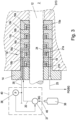
- Fig.4 shows a schematic of a purge panel 40 for providing the buffer gas BG for the pressure packing 14.
- the purge panel 40 can be arranged in a purge panel enclosure 48 (as indicated in Fig.4 ), could however also be proved without enclosure. In case of a purge panel enclosure 48 there would preferably be provided a door that allows access to the instrumentation arranged in the purge panel enclosure 48.
- the purge panel 40 has a buffer gas inlet 41 for connecting a buffer gas BG supply line 42, that is for example connected to a buffer gas supply 38. If the purge panel 40 has a purge panel enclosure 48 and the buffer gas supply is provided in the purge panel enclosure 48, the buffer gas inlet 41 could also be avoided.
- the purge panel 40 has a sensing line inlet 43 for connecting the sensing line 35 to the purge panel 40.
- the sensing line 35 extends from the sensing line inlet 43 into the purge panel 40.
- the end of the sensing line 35 in the purge panel 40 is closed, so that there is no gas flow in the sensing line 35 when connected to the purge panel 40.
- the purge panel 40 has a buffer gas outlet 44, to which the buffer gas feeding line 20 is connected in use of the purge panel 40.
- the buffer gas inlet 41 and the buffer gas outlet 44 are connected in the purge panel 40 by a gas line 46.
- a pressure regulator 37 is provided, in the example of Fig.4 a differential pressure control valve, for setting the puffer gas pressure p B at the buffer gas output connector 44, and by that also in the buffer gas feeding line 20 connected thereto.
- the sensing line 35 is connected to a pilot input 45 of the differential pressure control valve at which the sensing line 35 terminates.
- the differential pressure which is preferably preset, between the pressure at the pilot input 45 and the output pressure of the differential pressure control valve (the buffer gas pressure p B ) is set by the differential pressure control valve.
- the buffer gas pressure p B is offset from the pilot pressure (vent pressure p V ) by the preset differential pressure and follows the vent pressure p V in the sense line 35.
- the purge panel 40 When the purge panel 40 supplies more than one pressure packing 14 with buffer gas BG, in each case under control of a vent pressure p V in a sensing line 35 of the respective pressure packing, then the purge panel 40 could also be equipped with more than one pressure regulator 37. In this case, there would be a sensing line inlet 43 for each pressure regulator for connecting the respective sensing line 35 to the purge panel 40. There would also be a buffer gas output connector 44 for each pressure regulator 37 for connecting the respective buffer gas feeding line 20 to the purge panel 40.
- the purge panel 40 could also be equipped with additional instrumentation, as will be described with reference to Fig.5 .
- the buffer gas BG is fed into the purge panel 40 via buffer gas inlet 41, to which a buffer gas supply line 42, connected on the other end to a buffer gas supply 38, is connected when the purge panel 40 is in use.
- the buffer gas inlet 41 is connected to a gas line 46.
- an isolation valve 50 is arranged downstream of the buffer gas inlet 41. If an operator wants to perform a routine maintenance operation of the purge panel 40 and isolates the purge panel 40 from the buffer gas supply via the isolation valve 50, the purge panel 40 will remain pressurized and pose a hazard when the operator tries to open a component which is under pressure. Therefore, preferably an isolation valve 50 with downstream vent is used, which automatically depressurizes the panel as soon as the isolation valve 50 is switched into closed position. Such an isolation valve 50 shuts off the gas line 46 upstream of the isolation valve 50 when in closed position. But, when in closed position, the isolation valve 50 opens a vent port on the isolation valve 50 that is connected to the gas line 50 downstream of the isolation valve 50.
- the gas line 46 downstream of the isolation valve 50 is depressurized via the vent port when the isolation valve 50 is closed.
- Such an isolation valve 50 with downstream vent together with check valves 55 at the outlets guarantees operator safety in all situations.
- a filter 52 for filtering the buffer gas BG fed into the purge panel 40.
- a first pressure control valve 53 In the inlet section of the gas line 46, there can also be provided a first pressure control valve 53.
- the gas pressure of the buffer gas BG fed into the purge panel 40 could be varying for different reasons. It is therefore advantageous to set a specified gas pressure in the gas line 46 in the purge panel 40 via the first pressure control valve 53.
- the gas line 46 Downstream of the first pressure control valve 53 the gas line 46 is fed to the pressure regulator 37 for setting the desired buffer gas pressure as explained above.
- a second gas line 46a branches off from the gas line 46 downstream of the first pressure control valve 53 and upstream of the pressure regulator 37.
- a second pressure control valve 53a could be provided for setting the desired gas pressure in the second gas line 46a.
- the second gas line 46a Downstream of the second pressure control valve 53a, the second gas line 46a is connected to a number of buffer gas outlets 47a, 47b of the purge panel 40, in the embodiment of Fig.5 two buffer gas outlets 47a, 47b.
- a constant buffer gas BG pressure could be set via the first pressure control valve 53 and/or second pressure control valve 53a (if present).
- buffer gas outlets 47a, 47b could for example be connected to the distance piece buffer gas lines 32, 32a or intermediate packing buffer gas line 32b (see Fig.1 ) or to a partition packing buffer gas line for providing a buffer gas BG with constant gas pressure for purging the distance piece 13, 13a or for supplying the buffer gas barrier 18 to the intermediate packing 31 or partition packing 30.
- each second gas line 46a can be connected to a number of buffer gas outlets 47a, 47b.
- Fig. 5 there are two buffer gas outlets 44, 44a provided, for example, for supplying buffer gas BG to two pressure packings 14 of a reciprocating piston compressor 1.
- the buffer gas outlets 44, 44a are connected to the pressure regulator 37 as explained in Fig.4 .
- the purge panel 40 can also be equipped with a pressure relief valve 57 that is connected to the gas line 46 downstream of the pressure regulator 37, as in Fig. 5 .
- the pressure relief valve 57 would be set to a certain allowed buffer gas pressure p Bmax . If the buffer gas pressure p B in the gas line 46 exceeds this allowed buffer gas pressure p Bmax , the pressure relief valve 57 would open to prevent damage at the reciprocating piston compressor 1 connected to the purge panel 40, e.g. damage of the pressure packing 14.
- a second gas line 46a is provided in the purge panel 40 there could of course also be a second pressure relief valve 57 provided for the second gas line 46a.
- the release pressure of the second pressure relief valve 57 could of course also be set differently as compared to other pressure relief valves 57 in the purge panel 40.
- a pressure relief valve 57 could also open into an overpressure line 58 in the purge panel 40 which in turn could be connected to an overpressure outlet 59, that could open into atmosphere. This is especially preferred when the purge panel 40 is provided with a purge panel enclosure 48.
- a pressure indicator 51 could be used to display the acting pressure at certain locations in the gas line 46 and/or a second gas line 46a.
- a flow indicator 56 could be used to display the actual buffer gas flow through certain parts of the gas line 46 and/or a second gas line 46a.
- purge panel enclosure 48 it is advantageous when the purge panel enclosure 48 is open or transparent in the region of a monitoring instrument so that the monitoring instrument is visible from outside. To this end a door of the purge panel enclosure 48 could partly be transparent.
- the purge panel 40 can be designed to provide any required number of buffer gas outlets 44, 44a. Each buffer gas outlets 44, 44a could be connected to a separate pressure regulator 37, for allowing to set the buffer gas pressure p B at each buffer gas outlets 44, 44a separately. Some of the buffer gas outlets 44, 44a could however also be connected to a common pressure regulator 37 (as in Fig.5 ). In addition, there can also be provided a number of second gas lines 46a connected to a number of additional buffer gas outlets 47a, 47b, at which a constant buffer gas pressure p B could be set via a first pressure control valve 53 and/or second pressure control valve 53a (if present). This allows to adapt the purge panel 40 flexibly to the requirements of a specific reciprocating piston compressor 1.
- a valve could also be provided upstream of a certain buffer gas outlet 44, 44a, 47a, 47b to shut off this buffer gas outlet 44, 44a, 47a, 47b in case it is not needed.
- the purge panel 40 is arranged in an enclosure 48, it is advantageous for safety reasons to avoid hazardous process gas PG to accumulate in the enclosure 48 in case of malfunction.
- the sensing line 35 is filled with process gas PG mixed with some buffer gas BG.
- the sensing line 35 is gas-tight, but in reality, there is always the possibility of an accidental leakage in the enclosure 48 of the purge panel 40 and the possibility of fugitive leaks and accumulation of process gas PG in the enclosure cannot be excluded, which is a potential hazard.
- a pneumatic booster relay 54 could be used. Such a configuration is shown in Fig.6 .
- a pneumatic booster relay 54 can however also be provided in other embodiments of the purge panel 40, e.g. as in Fig.4 or Fig.5 .
- a pneumatic booster relay is a known pneumatic device that regulates the pressure of a stream of gas based on a pilot pressure.
- a pneumatic booster relay 54 has four ports, a supply port 54a, an outlet port 54b, a pilot port 54c and an exhaust port 54d. When a pilot pressure is applied to the pilot port 54c, the main valve assembly of the pneumatic booster relay 54 opens to allow flow from the supply port 54a to the outlet port 54b.
- the main valve moves to a rest position in which the outlet port 54b and the exhaust port 54d are blocked (not connected to the any other port) and will remain in this position until there is a change in the pilot pressure or outlet pressure. If the sensing assembly detects that the outlet pressure is higher than the pilot pressure, the exhaust port 54d opens to vent the excess pressure, for example into an exhaust line or into the surroundings. If the sensing assembly detects that the outlet pressure is lower than the pilot pressure, the main valve opens to connect the supply port 54a to the outlet port 54b for recharging the system to the pilot pressure. In that way, the output pressure at the output port 54b corresponds to the pilot pressure at the pilot port 54a.
- the pneumatic booster relay 54 When the pneumatic booster relay 54 is arranged outside of the enclosure 48 of the purge panel 40 and the sensing line 35 is connected to the pilot port 54c of the pneumatic booster relay 54, it can be ensured that no process gas PG enters the enclosure 48, as the pilot port 54c of the pneumatic booster relay 54 cannot be connected to the output port 54b of the pneumatic booster relay 54.
- the supply port 54a of the pneumatic booster relay 54 is connected to the gas line 46 of the purge panel 40 so that buffer gas is supplied to the pneumatic booster relay 54.
- the sensing line 35 would in this embodiment not be connected directly to the pilot input 45 of the differential regulator 37 but to the pilot port 54c of the pneumatic booster relay 54 and would terminate there.
- the pilot pressure of the pneumatic booster relay 54 corresponds again to the vent pressure p V in the sensing line 35.
- the output pressure of the buffer gas at the output port 54b of the pneumatic booster relay 54 corresponds also to the vent pressure p V .
- the output port 54b of the pneumatic booster relay 54 is therefore connected to the sensing line inlet 43 and further to the pilot input 45 of the differential regulator 37 to set the pilot pressure for the pressure regulator 37.
- Fig.6 shows an embodiment of the purge panel with a pressure regulator 37 for every buffer gas outlet 44, 44a.
- the buffer gas pressures p B at every buffer gas outlet 44, 44a can be set independently from each other by means of the respective pressure regulator 37.
- valves 62 are shown that allow to shut-off certain outlets of the purge panel 40 as need be.
- a purge panel 40 provisions can be made on the purge panel 40 to allow integration of digital measurement instruments 60, like digital pressure or flow transducer. To this end certain connectors 61 could be provided at the purge panel 40 at certain locations which allow connection of such digital measurement instruments 60. Usage of digital measurement instruments allow integration of a purge panel 40 in a digital control of the purge panel 40 or the reciprocating piston compressor 1.
- a pressure transducer PT is shown that is connected to a connected 61 at the purge panel 40.
- the measurement signal of the pressure transducer PT could be send to a control unit for further processing and could be used for monitoring and/or controlling the function of the purge panel 40.
Landscapes
- Engineering & Computer Science (AREA)
- Mechanical Engineering (AREA)
- General Engineering & Computer Science (AREA)
- Compressor (AREA)
Claims (16)
- Druckpackung für einen Hubkolbenkompressor (1), die Druckpackung umfassendeine Puffergasbarriere (18) an einer Niederdruckseite der Druckpackung (14), wobei die Puffergasbarriere (18) ein Puffergasvolumen (19) umfasst;eine Anzahl von Dichtringen (16) an einer gegenüberliegenden Hochdruckseite der Druckpackung (14);ein Entlüftungsvolumen (24) zwischen der Puffergasbarriere (18) und einem letzten Dichtring der Anzahl von Dichtringen (16) vor der Puffergasbarriere (18);eine Entlüftungsleitung (25), die mit dem Entlüftungsvolumen (24) verbunden ist;eine Puffergasspeiseleitung (20), die mit dem Puffergasvolumen (19) der Puffergasbarriere (18) verbunden ist;wobei Puffergas (BG) mit Puffergasdruck (pB) in das Puffergasvolumen (19) über die Puffergasspeiseleitung (20) während eines Betriebs der Druckpackung (14) zugeführt wird, wobei der Puffergasdruck (pB) höher als ein Entlüftungsdruck (pV) in dem Entlüftungsvolumen (24) ist,dadurch gekennzeichnet, dass die Druckpackung ferner umfassteine Sensorleitung (35), die an einem ersten Ende mit dem Entlüftungsvolumen (24) verbunden ist, wobei ein gegenüberliegendes zweites Ende der Sensorleitung (35) geschlossen ist, sodass in der Sensorleitung (35) kein Gasfluss vorhanden ist; undeinen Druckregler (37), der mit der Puffergasspeiseleitung (20) verbunden ist, zum Einstellen des Puffergasdrucks (pB) in der Puffergasspeiseleitung (20);wobei, während des Betriebs der Druckpackung (14), der Druckregler (37) den Druck in der Sensorleitung (35) als Pilotdruck zum Einstellen des Puffergasdrucks (pB) verwendet.
- Druckpackung nach Anspruch 1, dadurch gekennzeichnet, dass der Druckregler (37) ein Differenzdrucksteuerventil mit einem Piloteingang (45) ist, wobei die Sensorleitung (35) mit dem Piloteingang (45) des Differenzdrucksteuerventils verbunden ist.
- Druckpackung nach Anspruch 1, dadurch gekennzeichnet, dass die Sensorleitung (35) in einem oberen Teil der Druckpackung (14) angeordnet ist.
- Druckpackung nach Anspruch 1, ferner einschließlich eines Bedienpultes (40), wobei der Druckregler (37) in einer ersten Gasleitung (46) des Bedienpults (40) angeordnet ist, die einen Puffergaseinlass (41) und einen Puffergasauslass (44) des Bedienpults (40) verbindet, wobei der Puffergasauslass (44) mit der Puffergasspeiseleitung (20) verbunden ist und der Puffergaseinlass (41) eine Puffergaszufuhr (38) mit dem Bedienpult (40) verbindet, und ferner einschließlich eines Sensorleitungseinlasses (43), der am Bedienpult (40) angeordnet ist und der mit der Sensorleitung (35) verbunden ist.
- Druckpackung nach Anspruch 1, ferner einschließlich eines Bedienpults (40) mit einem Gehäuse (48), wobei der Druckregler (37) in einer ersten Gasleitung (46) des Bedienpults (40) angeordnet ist, die einen Puffergaseinlass (41) und einen Puffergasauslass (44) des Bedienpults (40) verbindet, wobei der Puffergasauslass (44) mit der Puffergasspeiseleitung (BG) verbunden ist und der Puffergaseinlass (41) eine Puffergaszufuhr (38) mit dem Bedienpult (40) verbindet, und dass ein pneumatisches Druckerhöhungsrelais (54) außerhalb des Gehäuses (48) bereitgestellt ist, wohingegen die Sensorleitung (35) mit einem Pilotanschluss (54c) des pneumatischen Druckerhöhungsrelais (54) verbunden ist, die erste Gasleitung (46) mit einem Zufuhranschluss (54a) des pneumatischen Druckerhöhungsrelais (54) verbunden ist und ein Ausgangsanschluss (54b) des pneumatischen Druckerhöhungsrelais (54) mit einem Sensorleitungseinlass (43) des Bedienpults (40) verbunden ist.
- Druckpackung nach Anspruch 4 oder 5, dadurch gekennzeichnet, dass der Druckregler (37) mit mehreren Puffergasauslässen (44, 44a) des Bedienpults (40) verbunden ist.
- Druckpackung nach Anspruch 4 oder 5, wobei der Druckregler (37) mehrere Druckregler einschließt, die mit der ersten Gasleitung (46) im Bedienpult (40) verbunden sind, und ferner einschließlich eines Puffergasauslasses (44, 44a) und eines Sensorleitungseinlasses (43), die für jeden der mehreren Druckregler bereitgestellt sind.
- Druckpackung nach Anspruch 4 oder 5, ferner einschließlich eines Absperrventils (50) mit stromabwärtiger Entlüftung in der ersten Gasleitung (46) stromabwärts des Puffergaseinlasses (41).
- Druckpackung nach Anspruch 4 oder 5, ferner einschließlich eines Filters (52) in der ersten Gasleitung (46) stromabwärts des Puffergaseinlasses (41).
- Druckpackung nach Anspruch 4 oder 5, ferner einschließlich eines ersten Drucksteuerventils (53) in der ersten Gasleitung (46) stromaufwärts des Druckreglers (37).
- Druckpackung nach Anspruch 10, ferner einschließlich mindestens einer zweiten Gasleitung (46a), die stromabwärts des ersten Drucksteuerventils (53) von der ersten Gasleitung (46) abzweigt, und mindestens eines zusätzlichen Puffergasauslasses (47a, 47b) am Bedienpult (40), der mit der mindestens einen zweiten Gasleitung (46a) verbunden ist.
- Druckpackung nach Anspruch 11, ferner einschließlich eines zweiten Drucksteuerventils (53a) in der mindestens einen zweiten Gasleitung (46a).
- Druckpackung nach Anspruch 4 oder 5, ferner einschließlich eines Überdruckventils (57) im Bedienpult (40), das mit der Gasleitung (46) verbunden ist.
- Druckpackung nach Anspruch 11, ferner einschließlich eines Überdruckventils (57) im Bedienpult (40), das mit der mindestens einen zweiten Gasleitung (46a) verbunden ist.
- Hubkolbenkompressor mit einer Druckpackung nach einem der Ansprüche 1 bis 14.
- Verfahren zum Betreiben einer Druckpackung (14) für einen Hubkolbenkompressor (1), wobei die Druckpackung (14) eine Puffergasbarriere (18) an einer Niederdruckseite der Druckpackung (14) und eine Anzahl von Dichtringen (16) an einer gegenüberliegenden Hochdruckseite der Druckpackung (14) aufweist, wobei ein Entlüftungsvolumen (24) in der Druckpackung (14) zwischen der Puffergasbarriere (18) und dem letzten Dichtring der Anzahl von Dichtringen (16) vor der Puffergasbarriere (18) vorgesehen ist, wobei eine Entlüftungsleitung (25) mit dem Entlüftungsvolumen verbunden ist, wobei ein Puffergasvolumen (19) in der Puffergasbarriere (18) vorgesehen ist, das mit einer Puffergasspeiseleitung (20) verbunden ist, wobei ein Puffergas (BG) mit Puffergasdruck (pB) in das Puffergasvolumen (19) über die Puffergasspeiseleitung (20) mit dem Puffergasdruck (pB) zugeführt wird und der Puffergasdruck (pB) höher als ein Entlüftungsdruck (pV) in dem Entlüftungsvolumen (24) ist,
dadurch gekennzeichnet, dass eine Sensorleitung (35) an einem ersten Ende mit dem Entlüftungsvolumen (24) verbunden ist, wobei ein gegenüberliegendes zweites Ende der Sensorleitung (35) geschlossen ist, sodass in der Sensorleitung kein Gasfluss vorhanden ist, und ein Druckregler (37) mit der Puffergasspeiseleitung (20) verbunden ist, zum Einstellen des Puffergasdrucks (pB) in der Puffergasspeiseleitung (20), wobei der Druck in der Sensorleitung (35) als Pilotdruck für den Druckregler (37) zum Einstellen des Puffergasdrucks (pB) verwendet wird.
Applications Claiming Priority (2)
| Application Number | Priority Date | Filing Date | Title |
|---|---|---|---|
| US17/740,323 US12435716B2 (en) | 2022-05-09 | 2022-05-09 | Pressure packing for a reciprocating piston compressor with buffer gas barrier |
| PCT/EP2023/061889 WO2023217640A1 (en) | 2022-05-09 | 2023-05-05 | Pressure packing for a reciprocating piston compressor with buffer gas barrier |
Publications (3)
| Publication Number | Publication Date |
|---|---|
| EP4374072A1 EP4374072A1 (de) | 2024-05-29 |
| EP4374072B1 true EP4374072B1 (de) | 2025-02-26 |
| EP4374072C0 EP4374072C0 (de) | 2025-02-26 |
Family
ID=86425900
Family Applications (1)
| Application Number | Title | Priority Date | Filing Date |
|---|---|---|---|
| EP23725184.8A Active EP4374072B1 (de) | 2022-05-09 | 2023-05-05 | Druckpackung für hubkolbenverdichter mit puffergassperre |
Country Status (6)
| Country | Link |
|---|---|
| US (1) | US12435716B2 (de) |
| EP (1) | EP4374072B1 (de) |
| JP (1) | JP7669590B2 (de) |
| CN (1) | CN118076808A (de) |
| CA (1) | CA3232555A1 (de) |
| WO (1) | WO2023217640A1 (de) |
Family Cites Families (30)
| Publication number | Priority date | Publication date | Assignee | Title |
|---|---|---|---|---|
| US3019739A (en) * | 1959-03-23 | 1962-02-06 | Union Carbide Corp | High pressure pumping apparatus |
| CH482953A (de) * | 1967-07-07 | 1969-12-15 | Sulzer Ag | Kolbenmaschine |
| CH511372A (de) * | 1969-06-30 | 1971-08-15 | Burckhardt Ag Maschf | Einrichtung zur zentrischen Führung des Kolbens im Arbeitszylinder von Hochdruck-Kompressoren oder -Pumpen |
| US3834715A (en) * | 1972-04-26 | 1974-09-10 | Dart Ind Inc | Pressure seal assembly |
| GB9307775D0 (en) * | 1993-04-15 | 1993-06-02 | Framo Dev Ltd | Sealing system |
| GB0004239D0 (en) * | 2000-02-24 | 2000-04-12 | Crane John Uk Ltd | Seal assemblies |
| JP2004116330A (ja) * | 2002-09-25 | 2004-04-15 | Hitachi Industries Co Ltd | 往復圧縮機およびそのガス漏れ防止装置 |
| JP2004116329A (ja) * | 2002-09-25 | 2004-04-15 | Hitachi Industries Co Ltd | 往復圧縮機 |
| US7784395B2 (en) * | 2007-03-28 | 2010-08-31 | Clyde Union Inc. | Zero emissions reciprocating pump |
| JP2009062871A (ja) * | 2007-09-06 | 2009-03-26 | Hitachi Plant Technologies Ltd | 往復圧縮機 |
| JP5059662B2 (ja) | 2008-03-06 | 2012-10-24 | 株式会社神戸製鋼所 | 往復動圧縮機のガス漏洩防止システム |
| EP2376821B1 (de) * | 2008-12-15 | 2013-07-10 | Flowserve Management Company | System zur rückgewinnung von dichtungsleckgas |
| AT507564B1 (de) * | 2009-01-12 | 2010-06-15 | Hoerbiger Kompressortech Hold | Dichtanordnung zur abdichtung einer kolbenstange eines kolbenkompressors |
| CN201650839U (zh) | 2010-02-02 | 2010-11-24 | 成都一通密封有限公司 | 裂解气压缩机干气密封 |
| AT510171B1 (de) * | 2011-02-17 | 2012-02-15 | Hoerbiger Kompressortech Hold | Dichtpackung für eine hin- und hergehende kolbenstange eines kolbenkompressors |
| NL2006718C2 (en) * | 2011-05-04 | 2012-11-06 | Thomassen Compression Syst Bv | Piston compressor for compressing gas. |
| ITCO20110057A1 (it) * | 2011-12-05 | 2013-06-06 | Nuovo Pignone Spa | Tenuta a gas secco per buffer ad alta pressione di pompa per co2 supercritico |
| ITCO20120020A1 (it) * | 2012-04-27 | 2013-10-28 | Nuovo Pignone Srl | Compressore, alimentazione del gas di tenuta e metodo |
| AT512945B1 (de) * | 2012-06-04 | 2013-12-15 | Hoerbiger Kompressortech Hold | Dichtanordnung zur Abdichtung einer hin- und hergehenden Kolbenstange eines Kolbenkompressors |
| PL2885539T3 (pl) * | 2012-06-22 | 2021-11-15 | Nuovo Pignone S.R.L. | Sprężarka tłokowa, uszczelnienie ciśnieniowe i sposób |
| AT513836B1 (de) * | 2013-09-23 | 2014-08-15 | Hoerbiger Kompressortech Hold | Kompressor mit und Verfahren zur Spülung des Kompressorgehäuses mit Spülgas |
| JP6577343B2 (ja) * | 2015-11-17 | 2019-09-18 | 株式会社日本製鋼所 | ラビリンスピストン式往復動圧縮機 |
| IT201600085635A1 (it) * | 2016-08-17 | 2018-02-17 | Nuovo Pignone Tecnologie Srl | Tenuta per l'asta di un pistone |
| US10900476B2 (en) * | 2016-09-02 | 2021-01-26 | Southwest Research Institute | Natural gas reciprocating compressor |
| US10989215B2 (en) * | 2017-09-05 | 2021-04-27 | Solar Turbines Incorporated | Compressor system equipped for fugitive gas handling and fugitive gas system operating method |
| FR3072136B1 (fr) * | 2017-10-10 | 2021-11-19 | Atlas Copco Crepelle S A S | Systeme d'etancheisation d'une tige de piston pour une machine a mouvement alternatif et procede pour l'etancheisation d'une telle tige de piston |
| JP7360387B2 (ja) * | 2018-07-19 | 2023-10-12 | 株式会社荏原製作所 | シールシステム、および該シールシステムを備えたポンプシステム |
| US10883483B2 (en) * | 2018-09-28 | 2021-01-05 | Air Products And Chemicals, Inc. | Seal assembly for reciprocating compressor |
| GB2592179B (en) * | 2019-10-04 | 2022-03-30 | Weir Minerals Europe Ltd | Seal assembly |
| CN113915335A (zh) * | 2021-10-14 | 2022-01-11 | 安瑞科(蚌埠)压缩机有限公司 | 一种活塞式压缩机无泄漏密封装置 |
-
2022
- 2022-05-09 US US17/740,323 patent/US12435716B2/en active Active
-
2023
- 2023-05-05 EP EP23725184.8A patent/EP4374072B1/de active Active
- 2023-05-05 CA CA3232555A patent/CA3232555A1/en active Pending
- 2023-05-05 JP JP2024523179A patent/JP7669590B2/ja active Active
- 2023-05-05 CN CN202380013941.6A patent/CN118076808A/zh active Pending
- 2023-05-05 WO PCT/EP2023/061889 patent/WO2023217640A1/en not_active Ceased
Also Published As
| Publication number | Publication date |
|---|---|
| WO2023217640A1 (en) | 2023-11-16 |
| EP4374072C0 (de) | 2025-02-26 |
| US20230358226A1 (en) | 2023-11-09 |
| EP4374072A1 (de) | 2024-05-29 |
| CN118076808A (zh) | 2024-05-24 |
| JP7669590B2 (ja) | 2025-04-28 |
| US12435716B2 (en) | 2025-10-07 |
| JP2024543314A (ja) | 2024-11-21 |
| CA3232555A1 (en) | 2023-11-16 |
Similar Documents
| Publication | Publication Date | Title |
|---|---|---|
| US4193603A (en) | Sealing system for a turbomachine | |
| US2853020A (en) | Shaft seal | |
| US10094381B2 (en) | Vacuum pump system with light gas pumping and leak detection apparatus comprising the same | |
| EP2631489A1 (de) | Verdichter | |
| EP2885539B1 (de) | Kolbenkompressor, druckverpackung und verfahren dafür | |
| US20110094225A1 (en) | Internal combustion engine | |
| EP3610139B1 (de) | Verfahren zur steuerung des öldrucks einer ölpumpe in einem verbrennungsmotor und eine öldruckanordnung | |
| US9624785B2 (en) | System for monitoring health of a seal | |
| US20150308443A1 (en) | Compressor with thrust balancing and method thereof | |
| US6799112B1 (en) | Methods and apparatus for operating gas turbine engines | |
| CA2991931A1 (en) | Apparatus and method for controlling a pressure differential across a seal of a bearing chamber | |
| EP4374072B1 (de) | Druckpackung für hubkolbenverdichter mit puffergassperre | |
| GB2541278A (en) | Screw machine and method for operating the same | |
| EP4144989A1 (de) | Verbesserter hubkolbenkompressor | |
| US6641370B2 (en) | Vacuum pump apparatus having improved sealing structure | |
| EP3803116A1 (de) | Pneumatischer überspannungsschutz | |
| US11767847B2 (en) | Compressor or vacuum pump device, a liquid return system for such a compressor or vacuum pump device and a method for draining liquid from a gearbox of such a compressor or vacuum pump device | |
| CN213870176U (zh) | 一种压缩机用油位控制系统、工况控制系统 | |
| RU2623323C2 (ru) | Турбомашина и способ ее работы | |
| US11585334B2 (en) | Vapor recovery system and method for packing cases and other gas emitting components | |
| CN114439725A (zh) | 一种压缩机用油位控制系统、工况控制系统及其应用 | |
| US20230175498A1 (en) | Fluid recovery system | |
| JPWO2019111661A1 (ja) | 給液式スクリュー圧縮機 | |
| WO2024119512A1 (zh) | 往复式压缩机 | |
| CN116104795A (zh) | 轴向进气轴流压缩机及其密封系统、密封方法 |
Legal Events
| Date | Code | Title | Description |
|---|---|---|---|
| STAA | Information on the status of an ep patent application or granted ep patent |
Free format text: STATUS: UNKNOWN |
|
| STAA | Information on the status of an ep patent application or granted ep patent |
Free format text: STATUS: THE INTERNATIONAL PUBLICATION HAS BEEN MADE |
|
| PUAI | Public reference made under article 153(3) epc to a published international application that has entered the european phase |
Free format text: ORIGINAL CODE: 0009012 |
|
| STAA | Information on the status of an ep patent application or granted ep patent |
Free format text: STATUS: REQUEST FOR EXAMINATION WAS MADE |
|
| 17P | Request for examination filed |
Effective date: 20240220 |
|
| AK | Designated contracting states |
Kind code of ref document: A1 Designated state(s): AL AT BE BG CH CY CZ DE DK EE ES FI FR GB GR HR HU IE IS IT LI LT LU LV MC ME MK MT NL NO PL PT RO RS SE SI SK SM TR |
|
| GRAP | Despatch of communication of intention to grant a patent |
Free format text: ORIGINAL CODE: EPIDOSNIGR1 |
|
| STAA | Information on the status of an ep patent application or granted ep patent |
Free format text: STATUS: GRANT OF PATENT IS INTENDED |
|
| DAV | Request for validation of the european patent (deleted) | ||
| DAX | Request for extension of the european patent (deleted) | ||
| INTG | Intention to grant announced |
Effective date: 20240801 |
|
| GRAJ | Information related to disapproval of communication of intention to grant by the applicant or resumption of examination proceedings by the epo deleted |
Free format text: ORIGINAL CODE: EPIDOSDIGR1 |
|
| STAA | Information on the status of an ep patent application or granted ep patent |
Free format text: STATUS: REQUEST FOR EXAMINATION WAS MADE |
|
| GRAP | Despatch of communication of intention to grant a patent |
Free format text: ORIGINAL CODE: EPIDOSNIGR1 |
|
| STAA | Information on the status of an ep patent application or granted ep patent |
Free format text: STATUS: GRANT OF PATENT IS INTENDED |
|
| INTC | Intention to grant announced (deleted) | ||
| INTG | Intention to grant announced |
Effective date: 20241202 |
|
| GRAS | Grant fee paid |
Free format text: ORIGINAL CODE: EPIDOSNIGR3 |
|
| GRAA | (expected) grant |
Free format text: ORIGINAL CODE: 0009210 |
|
| STAA | Information on the status of an ep patent application or granted ep patent |
Free format text: STATUS: THE PATENT HAS BEEN GRANTED |
|
| AK | Designated contracting states |
Kind code of ref document: B1 Designated state(s): AL AT BE BG CH CY CZ DE DK EE ES FI FR GB GR HR HU IE IS IT LI LT LU LV MC ME MK MT NL NO PL PT RO RS SE SI SK SM TR |
|
| REG | Reference to a national code |
Ref country code: GB Ref legal event code: FG4D |
|
| REG | Reference to a national code |
Ref country code: CH Ref legal event code: EP |
|
| REG | Reference to a national code |
Ref country code: DE Ref legal event code: R096 Ref document number: 602023002224 Country of ref document: DE |
|
| REG | Reference to a national code |
Ref country code: IE Ref legal event code: FG4D |
|
| U01 | Request for unitary effect filed |
Effective date: 20250318 |
|
| U07 | Unitary effect registered |
Designated state(s): AT BE BG DE DK EE FI FR IT LT LU LV MT NL PT RO SE SI Effective date: 20250324 |
|
| PG25 | Lapsed in a contracting state [announced via postgrant information from national office to epo] |
Ref country code: RS Free format text: LAPSE BECAUSE OF FAILURE TO SUBMIT A TRANSLATION OF THE DESCRIPTION OR TO PAY THE FEE WITHIN THE PRESCRIBED TIME-LIMIT Effective date: 20250526 |
|
| PG25 | Lapsed in a contracting state [announced via postgrant information from national office to epo] |
Ref country code: PL Free format text: LAPSE BECAUSE OF FAILURE TO SUBMIT A TRANSLATION OF THE DESCRIPTION OR TO PAY THE FEE WITHIN THE PRESCRIBED TIME-LIMIT Effective date: 20250226 |
|
| U20 | Renewal fee for the european patent with unitary effect paid |
Year of fee payment: 3 Effective date: 20250530 |
|
| PG25 | Lapsed in a contracting state [announced via postgrant information from national office to epo] |
Ref country code: ES Free format text: LAPSE BECAUSE OF FAILURE TO SUBMIT A TRANSLATION OF THE DESCRIPTION OR TO PAY THE FEE WITHIN THE PRESCRIBED TIME-LIMIT Effective date: 20250226 |
|
| PG25 | Lapsed in a contracting state [announced via postgrant information from national office to epo] |
Ref country code: IS Free format text: LAPSE BECAUSE OF FAILURE TO SUBMIT A TRANSLATION OF THE DESCRIPTION OR TO PAY THE FEE WITHIN THE PRESCRIBED TIME-LIMIT Effective date: 20250626 Ref country code: NO Free format text: LAPSE BECAUSE OF FAILURE TO SUBMIT A TRANSLATION OF THE DESCRIPTION OR TO PAY THE FEE WITHIN THE PRESCRIBED TIME-LIMIT Effective date: 20250526 |
|
| PG25 | Lapsed in a contracting state [announced via postgrant information from national office to epo] |
Ref country code: HR Free format text: LAPSE BECAUSE OF FAILURE TO SUBMIT A TRANSLATION OF THE DESCRIPTION OR TO PAY THE FEE WITHIN THE PRESCRIBED TIME-LIMIT Effective date: 20250226 |
|
| PG25 | Lapsed in a contracting state [announced via postgrant information from national office to epo] |
Ref country code: GR Free format text: LAPSE BECAUSE OF FAILURE TO SUBMIT A TRANSLATION OF THE DESCRIPTION OR TO PAY THE FEE WITHIN THE PRESCRIBED TIME-LIMIT Effective date: 20250527 |
|
| PG25 | Lapsed in a contracting state [announced via postgrant information from national office to epo] |
Ref country code: SM Free format text: LAPSE BECAUSE OF FAILURE TO SUBMIT A TRANSLATION OF THE DESCRIPTION OR TO PAY THE FEE WITHIN THE PRESCRIBED TIME-LIMIT Effective date: 20250226 |
|
| PG25 | Lapsed in a contracting state [announced via postgrant information from national office to epo] |
Ref country code: CZ Free format text: LAPSE BECAUSE OF FAILURE TO SUBMIT A TRANSLATION OF THE DESCRIPTION OR TO PAY THE FEE WITHIN THE PRESCRIBED TIME-LIMIT Effective date: 20250226 |
|
| PG25 | Lapsed in a contracting state [announced via postgrant information from national office to epo] |
Ref country code: SK Free format text: LAPSE BECAUSE OF FAILURE TO SUBMIT A TRANSLATION OF THE DESCRIPTION OR TO PAY THE FEE WITHIN THE PRESCRIBED TIME-LIMIT Effective date: 20250226 |
|
| PLBE | No opposition filed within time limit |
Free format text: ORIGINAL CODE: 0009261 |
|
| STAA | Information on the status of an ep patent application or granted ep patent |
Free format text: STATUS: NO OPPOSITION FILED WITHIN TIME LIMIT |
|
| PG25 | Lapsed in a contracting state [announced via postgrant information from national office to epo] |
Ref country code: MC Free format text: LAPSE BECAUSE OF FAILURE TO SUBMIT A TRANSLATION OF THE DESCRIPTION OR TO PAY THE FEE WITHIN THE PRESCRIBED TIME-LIMIT Effective date: 20250226 |
|
| 26N | No opposition filed |
Effective date: 20251127 |