EP4371908A2 - Automatisiertes lager- und entnahmesystem - Google Patents
Automatisiertes lager- und entnahmesystem Download PDFInfo
- Publication number
- EP4371908A2 EP4371908A2 EP23216435.0A EP23216435A EP4371908A2 EP 4371908 A2 EP4371908 A2 EP 4371908A2 EP 23216435 A EP23216435 A EP 23216435A EP 4371908 A2 EP4371908 A2 EP 4371908A2
- Authority
- EP
- European Patent Office
- Prior art keywords
- container handling
- storage
- handling vehicle
- container
- grid
- Prior art date
- Legal status (The legal status is an assumption and is not a legal conclusion. Google has not performed a legal analysis and makes no representation as to the accuracy of the status listed.)
- Withdrawn
Links
Images


Classifications
-
- G—PHYSICS
- G05—CONTROLLING; REGULATING
- G05B—CONTROL OR REGULATING SYSTEMS IN GENERAL; FUNCTIONAL ELEMENTS OF SUCH SYSTEMS; MONITORING OR TESTING ARRANGEMENTS FOR SUCH SYSTEMS OR ELEMENTS
- G05B19/00—Programme-control systems
- G05B19/02—Programme-control systems electric
- G05B19/418—Total factory control, i.e. centrally controlling a plurality of machines, e.g. direct or distributed numerical control [DNC], flexible manufacturing systems [FMS], integrated manufacturing systems [IMS] or computer integrated manufacturing [CIM]
- G05B19/4189—Total factory control, i.e. centrally controlling a plurality of machines, e.g. direct or distributed numerical control [DNC], flexible manufacturing systems [FMS], integrated manufacturing systems [IMS] or computer integrated manufacturing [CIM] characterised by the transport system
- G05B19/41895—Total factory control, i.e. centrally controlling a plurality of machines, e.g. direct or distributed numerical control [DNC], flexible manufacturing systems [FMS], integrated manufacturing systems [IMS] or computer integrated manufacturing [CIM] characterised by the transport system using automatic guided vehicles [AGV]
-
- B—PERFORMING OPERATIONS; TRANSPORTING
- B65—CONVEYING; PACKING; STORING; HANDLING THIN OR FILAMENTARY MATERIAL
- B65G—TRANSPORT OR STORAGE DEVICES, e.g. CONVEYORS FOR LOADING OR TIPPING, SHOP CONVEYOR SYSTEMS OR PNEUMATIC TUBE CONVEYORS
- B65G1/00—Storing articles, individually or in orderly arrangement, in warehouses or magazines
- B65G1/02—Storage devices
- B65G1/04—Storage devices mechanical
- B65G1/0464—Storage devices mechanical with access from above
-
- B—PERFORMING OPERATIONS; TRANSPORTING
- B60—VEHICLES IN GENERAL
- B60L—PROPULSION OF ELECTRICALLY-PROPELLED VEHICLES; SUPPLYING ELECTRIC POWER FOR AUXILIARY EQUIPMENT OF ELECTRICALLY-PROPELLED VEHICLES; ELECTRODYNAMIC BRAKE SYSTEMS FOR VEHICLES IN GENERAL; MAGNETIC SUSPENSION OR LEVITATION FOR VEHICLES; MONITORING OPERATING VARIABLES OF ELECTRICALLY-PROPELLED VEHICLES; ELECTRIC SAFETY DEVICES FOR ELECTRICALLY-PROPELLED VEHICLES
- B60L50/00—Electric propulsion with power supplied within the vehicle
- B60L50/50—Electric propulsion with power supplied within the vehicle using propulsion power supplied by batteries or fuel cells
- B60L50/60—Electric propulsion with power supplied within the vehicle using propulsion power supplied by batteries or fuel cells using power supplied by batteries
- B60L50/66—Arrangements of batteries
-
- B—PERFORMING OPERATIONS; TRANSPORTING
- B60—VEHICLES IN GENERAL
- B60L—PROPULSION OF ELECTRICALLY-PROPELLED VEHICLES; SUPPLYING ELECTRIC POWER FOR AUXILIARY EQUIPMENT OF ELECTRICALLY-PROPELLED VEHICLES; ELECTRODYNAMIC BRAKE SYSTEMS FOR VEHICLES IN GENERAL; MAGNETIC SUSPENSION OR LEVITATION FOR VEHICLES; MONITORING OPERATING VARIABLES OF ELECTRICALLY-PROPELLED VEHICLES; ELECTRIC SAFETY DEVICES FOR ELECTRICALLY-PROPELLED VEHICLES
- B60L53/00—Methods of charging batteries, specially adapted for electric vehicles; Charging stations or on-board charging equipment therefor; Exchange of energy storage elements in electric vehicles
- B60L53/30—Constructional details of charging stations
-
- B—PERFORMING OPERATIONS; TRANSPORTING
- B60—VEHICLES IN GENERAL
- B60L—PROPULSION OF ELECTRICALLY-PROPELLED VEHICLES; SUPPLYING ELECTRIC POWER FOR AUXILIARY EQUIPMENT OF ELECTRICALLY-PROPELLED VEHICLES; ELECTRODYNAMIC BRAKE SYSTEMS FOR VEHICLES IN GENERAL; MAGNETIC SUSPENSION OR LEVITATION FOR VEHICLES; MONITORING OPERATING VARIABLES OF ELECTRICALLY-PROPELLED VEHICLES; ELECTRIC SAFETY DEVICES FOR ELECTRICALLY-PROPELLED VEHICLES
- B60L53/00—Methods of charging batteries, specially adapted for electric vehicles; Charging stations or on-board charging equipment therefor; Exchange of energy storage elements in electric vehicles
- B60L53/80—Exchanging energy storage elements, e.g. removable batteries
-
- B—PERFORMING OPERATIONS; TRANSPORTING
- B60—VEHICLES IN GENERAL
- B60S—SERVICING, CLEANING, REPAIRING, SUPPORTING, LIFTING, OR MANOEUVRING OF VEHICLES, NOT OTHERWISE PROVIDED FOR
- B60S5/00—Servicing, maintaining, repairing, or refitting of vehicles
- B60S5/06—Supplying batteries to, or removing batteries from, vehicles
-
- B—PERFORMING OPERATIONS; TRANSPORTING
- B65—CONVEYING; PACKING; STORING; HANDLING THIN OR FILAMENTARY MATERIAL
- B65G—TRANSPORT OR STORAGE DEVICES, e.g. CONVEYORS FOR LOADING OR TIPPING, SHOP CONVEYOR SYSTEMS OR PNEUMATIC TUBE CONVEYORS
- B65G1/00—Storing articles, individually or in orderly arrangement, in warehouses or magazines
- B65G1/02—Storage devices
- B65G1/04—Storage devices mechanical
- B65G1/0478—Storage devices mechanical for matrix-arrangements
-
- B—PERFORMING OPERATIONS; TRANSPORTING
- B65—CONVEYING; PACKING; STORING; HANDLING THIN OR FILAMENTARY MATERIAL
- B65G—TRANSPORT OR STORAGE DEVICES, e.g. CONVEYORS FOR LOADING OR TIPPING, SHOP CONVEYOR SYSTEMS OR PNEUMATIC TUBE CONVEYORS
- B65G1/00—Storing articles, individually or in orderly arrangement, in warehouses or magazines
- B65G1/02—Storage devices
- B65G1/04—Storage devices mechanical
- B65G1/137—Storage devices mechanical with arrangements or automatic control means for selecting which articles are to be removed
- B65G1/1373—Storage devices mechanical with arrangements or automatic control means for selecting which articles are to be removed for fulfilling orders in warehouses
- B65G1/1375—Storage devices mechanical with arrangements or automatic control means for selecting which articles are to be removed for fulfilling orders in warehouses the orders being assembled on a commissioning stacker-crane or truck
-
- B—PERFORMING OPERATIONS; TRANSPORTING
- B66—HOISTING; LIFTING; HAULING
- B66F—HOISTING, LIFTING, HAULING OR PUSHING, NOT OTHERWISE PROVIDED FOR, e.g. DEVICES WHICH APPLY A LIFTING OR PUSHING FORCE DIRECTLY TO THE SURFACE OF A LOAD
- B66F9/00—Devices for lifting or lowering bulky or heavy goods for loading or unloading purposes
- B66F9/06—Devices for lifting or lowering bulky or heavy goods for loading or unloading purposes movable, with their loads, on wheels or the like, e.g. fork-lift trucks
- B66F9/063—Automatically guided
-
- Y—GENERAL TAGGING OF NEW TECHNOLOGICAL DEVELOPMENTS; GENERAL TAGGING OF CROSS-SECTIONAL TECHNOLOGIES SPANNING OVER SEVERAL SECTIONS OF THE IPC; TECHNICAL SUBJECTS COVERED BY FORMER USPC CROSS-REFERENCE ART COLLECTIONS [XRACs] AND DIGESTS
- Y02—TECHNOLOGIES OR APPLICATIONS FOR MITIGATION OR ADAPTATION AGAINST CLIMATE CHANGE
- Y02T—CLIMATE CHANGE MITIGATION TECHNOLOGIES RELATED TO TRANSPORTATION
- Y02T10/00—Road transport of goods or passengers
- Y02T10/60—Other road transportation technologies with climate change mitigation effect
- Y02T10/70—Energy storage systems for electromobility, e.g. batteries
-
- Y—GENERAL TAGGING OF NEW TECHNOLOGICAL DEVELOPMENTS; GENERAL TAGGING OF CROSS-SECTIONAL TECHNOLOGIES SPANNING OVER SEVERAL SECTIONS OF THE IPC; TECHNICAL SUBJECTS COVERED BY FORMER USPC CROSS-REFERENCE ART COLLECTIONS [XRACs] AND DIGESTS
- Y02—TECHNOLOGIES OR APPLICATIONS FOR MITIGATION OR ADAPTATION AGAINST CLIMATE CHANGE
- Y02T—CLIMATE CHANGE MITIGATION TECHNOLOGIES RELATED TO TRANSPORTATION
- Y02T10/00—Road transport of goods or passengers
- Y02T10/60—Other road transportation technologies with climate change mitigation effect
- Y02T10/7072—Electromobility specific charging systems or methods for batteries, ultracapacitors, supercapacitors or double-layer capacitors
Definitions
- the present invention relates to an automated storage and retrieval system.
- the present invention relates to an automated storage and retrieval system comprising:
- the present invention also relates to a container handling vehicle for such an automated storage and retrieval system, the container handling vehicle comprising a lower part comprising a wheel assembly for guiding the container handling vehicle along a horizontal track system of the automated storage and retrieval system, and a storage space arranged centrally within the lower part for accommodating a storage container of the automated storage and retrieval system.
- WO2016/120075A1 shows an example of an automated storage and retrieval system of the type identified above.
- the disclosed container handling vehicles are dimensioned so that they have a footprint, i.e. a contact area against the track system, which has a horizontal extension that is equal to the horizontal extension of a grid cell. This allows the container handling vehicles to be operated simultaneously above neighbouring grid cells, liberating more space for the container handling vehicles to travel on the track system as compared to prior art systems.
- such a container handling vehicle i.e. a container handling vehicle having a footprint with a horizontal extension corresponding to the horizontal extension of a single grid cell, is sometimes referred to as a "single cell" container handling vehicle.
- the single cell design disclosed in WO2016/120075A1 and WO2015/193278A1 reduces the space required for the container handling vehicles to travel on the track system, thus allowing more vehicles to operate on the track system without interfering with each other.
- the container handling vehicles has a horizontal extension that is larger than a single grid cell.
- a battery replacement regime in which a container handling vehicle is instructed to move to a battery replacement station to have its onboard battery replaced when it nears depletion
- the protruding battery slot will, when the vehicle is positioned above a grid cell, protrude into a neighbouring grid cell. This will prevent other container handling vehicles from operating on the neighbouring grid cell, thus limiting the space available for other container handling vehicles to operate on the track system.
- the container handling vehicle is characterised in that it comprises a protruding section extending horizontally beyond the lower part and a recessed section arranged to accommodate the protruding section of another container handling vehicle when operating on the track system.
- the recessed section of each container handling vehicle is capable of accommodating the protruding sections of other container handling vehicles when they pass over a neighbouring grid cell, thus allowing container handling vehicles to travel along neighbouring rows of grid cells.
- the recessed section may have a shape which is complementary to the shape of the protruding section.
- the recessed section may have a different shape than the protruding section as long as the recessed section is capable of accommodating the protruding section of another vehicle when it passes a neighbouring grid cell.
- the recessed section may advantageously extend across the whole width or length of the container handling vehicle in a direction which is orthogonal to the direction in which the protruding section extends, thus allowing two vehicles to completely pass each other on adjacent grid cells.
- the recessed section forming the region of clearance may extend from one side of the container handling vehicle.
- the protruding section and the recessed section may be arranged at the upper part of the container handling vehicle.
- the wheel assembly may comprise a first set of wheels for engaging with the first set of tracks to guide movement of the container handling vehicle in the first direction, and a second set of wheels for engaging with the second set of tracks to guide movement of the container handling vehicle in the second direction.
- the container handling vehicle may comprise a container-receiving storage space for accommodating a storage container; a lifting device arranged to transport a storage container vertically between a storage position in a stack and a transport position in the storage space.
- the lifting device may comprise a gripping device being configured to releasably grip a storage container; and a lifting motor being configured to raise and lower the gripping device relative to the storage space.
- the container-receiving storage space may be arranged centrally within the lower part of the container handling vehicle.
- the protruding section may comprise at least one of: a rechargeable battery; a battery slot for housing a replaceable battery; and a sensor for establish the position of the vehicle on the track system or vis-à-vis other vehicles on the track system.
- the wheel assembly may comprise wheels which are arranged around the periphery of the storage space.
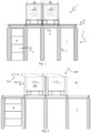
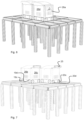
- the storage structure comprises a framework 2 on which a plurality of container handling vehicles 3a, 3b are operated.
- the framework 2 comprises a plurality of upright members 4 and a plurality of horizontal members 5, which are supported by the upright members 4.
- the members 4, 5 may typically be made of metal, e.g. extruded aluminium profiles.
- the framework 2 defines a three-dimensional storage grid comprising storage columns 7 arranged in rows, in which storage columns 7 storage containers 8, also known as bins, are stacked one on top of another to form stacks 9.
- Each storage container 8 may typically hold a plurality of product items (not shown), and the product items within a storage container 8 may be identical, or may be of different product types depending on the application of the system 1.
- the framework 2 guards against horizontal movement of the stacks 9 of storage containers 8, and guides vertical movement of the containers 8, but does normally not otherwise support the storage containers 8 when stacked.
- the horizontal members 5 comprise a rail or track system 10 arranged in a horizontal plane P above the storage columns 7 (see Figs. 1 and 3 ), on which track system 10 the plurality of container handling vehicles 3 can move laterally above the storage columns 7 to raise storage containers 8 from and lower storage containers 8 into the storage columns 7, and also to transport the storage containers 8 above the storage columns 7.
- the track system 10 comprises a first set of parallel rails or tracks 11 arranged to guide movement of the container handling vehicles 3 in a first direction X, and a second set of parallel rails or tracks 12 arranged perpendicular to the first set of tracks 11 to guide movement of the container handling vehicles 3 in a second direction Y, which is perpendicular to the first direction X.
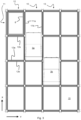
- the track system 10 forms a grid structure or grid pattern 13 in the horizontal plane P (see Fig. 3 ).
- the grid pattern 13 comprises a plurality of rectangular and uniform grid locations or grid cells 14 (see Fig. 8 ), where each grid cell 14 comprises a grid opening 15 which is delimited by a pair of tracks 11a, 11b of the first set of tracks 11 and a pair of tracks 12a, 12b of the second set of tracks 12.
- the grid cell 14 is indicated by a box having dashed borders and the grid opening 15 is indicated by a hatched area.
- tracks 11a and 11b form pairs of tracks defining parallel rows of grid cells running in the X direction
- tracks 12a and 12b form pairs of tracks defining parallel rows of grid cells running in the Y direction.
- Each grid cell 14 has a width W c which is typically within the interval of 30 to 150 cm, and a length L c which is typically within the interval of 50 to 200 cm.
- Each grid opening 15 has a width W o and a length L o which is typically 2 to 10 cm less than the width W c , and the length L c , respectively, of the grid cell 14.
- neighbouring grid cells are arranged in contact with each other such that there is no space there-between.
- FIG. 10 One embodiment of a container handling vehicle 3 according to the invention will now be discussed in more detail with additional reference to Figs. 10 to 12 .
- Each container handling vehicle 3 comprises a vehicle body 17 and a wheel assembly 18 arranged in a lower section or part 17a (see Fig. 12 ) of the vehicle body 17 to enable the lateral movement of the container handling vehicle 3, i.e. the movement of the vehicle 3 in the X and Y directions (see Fig. 4 ).
- the wheel assembly 18 comprises a first set of wheels 19, which is arranged to engage with a pair of tracks 11a, 11b of the first set of tracks 11, and a second set of wheels 20, which is arranged to engage with a pair of tracks 12a, 12b of the second set of tracks 12 (see Fig. 10 ). At least one of the set of wheels 19, 20 can be lifted and lowered, so that the first set of wheels 19 and/or the second set of wheels 20 can be brought to engage with the respective set of tracks 11, 12 at any one time.
- Each set of wheels 19, 20 comprises four wheels 19a, 19b, 19c, 19d; 20a, 20b, 20c, 20d arranged along the sides of the vehicle (see Figs. 4 and 7 ).
- Wheels 19a and 19b are arranged in a first vertical plane
- wheels 19c and 19d are arranged in a second vertical plane which is parallel to the first vertical plane and arranged at a distance from the first vertical plane which corresponds to the distance between rails 11a and 11b (see Fig. 8 ).
- Wheels 20a and 20b are arranged in a third vertical plane, which is orthogonal to the vertical planes in which wheels 19a-19d are arranged, and wheels 20c and 20d are arranged in a fourth vertical plane which is parallel to the third vertical plane and arranged at a distance from the third vertical plane which corresponds to the distance between rails 12a and 12b.
- At least one of the wheels in each set 19, 20 is motorized in order to propel the vehicle 3 along the track system 10.
- the at least one motorized wheel in each set comprises a hub motor, i.e. an electric motor that is coupled to, or incorporated into, the hub of a wheel and drives the wheel directly.
- a hub motor i.e. an electric motor that is coupled to, or incorporated into, the hub of a wheel and drives the wheel directly.
- An example of a container handling vehicle with such a motor is disclosed in WO2016/120075A1 , the contents of which are incorporated herein by reference.
- Each container handling vehicle 3 comprises a storage compartment or storage space 24 arranged centrally within the lower part 7a of the vehicle body 17 for receiving and holding a storage container 8 when transporting the storage container 8 across the track system 10.
- the storage space 24 is arranged within the vehicle body 17 and can be accessed from below, i.e. from an opening (not shown) at the bottom of the container handling vehicle 3.
- Each container handling vehicle 3 also comprises a lifting device 21 (see Fig. 10 ) for vertical transportation of a storage container 8, e.g. lifting a storage container 8 from a storage column 7 and bringing it into the storage space 24, and also for lowering a storage container 8 from the storage space 24 into a storage column 7.
- the lifting device 21 comprises a latching or gripping device 22 which is arranged to releasably engage with a storage container 8.
- the lifting device also comprises a lifting motor 23 for lowering and raising the gripping device 22 so that the position of the gripping device 22 with respect to the vehicle body 17 can be adjusted in a third direction Z, which is orthogonal to the first direction X and the second direction Y (see also Fig. 4 ).
- the lifting motor 23 is arranged in a second, upper part or section 17b of the vehicle body 17 (see Fig. 12 ), which upper part 17b is located above the lower part 17a.
- one of the container handling vehicles 3 When a storage container 8 stored in the storage grid is to be accessed, one of the container handling vehicles 3 is instructed to retrieve the target storage container 8 from its position in the storage grid and to transport the target storage container 8 to an access station (not shown) where it can be access from outside of the storage grid or transferred out of the storage grid.
- This operation involves moving the container handling vehicle 3 to the grid cell 14 above the storage column 7 in which the target storage container is positioned and retrieving the storage container from the storage column 7 using the container handling vehicle's lifting device 21.
- This step involves using the lifting device 21 to lift the storage container from the storage column 7 through the grid opening 15 of the grid cell 14 and into the storage space 24 of the vehicle 3.
- the operation also involves temporarily moving the above-positioned storage containers prior to lifting the target storage container from the storage column 7.
- This step which is sometimes referred to as "digging" within the art, may be performed with the same container handling vehicle that is subsequently used for transporting the target storage container to the access station, or with one or a plurality of other cooperating container handling vehicles.
- the automated storage and retrieval system may have container handling vehicles specifically dedicated to the task of temporarily removing storage containers from a storage column. Once the target storage container has been removed from the storage column, the temporarily removed storage containers can be repositioned into the original storage column. However, the removed storage containers may alternatively be relocated to other storage columns.
- the vehicle transports the storage container to the access station where it is unloaded.
- the access station may typically comprise a grid location at the periphery of the storage grid where the storage container can be accessed manually or transported further using a suitable conveyor system.
- one of the container handling vehicles 3 When a storage container 8 is to be stored in the storage grid, one of the container handling vehicles 3 is instructed to pick up the storage container from a pick-up station (not shown), which may also double as an access station, and transport it to a grid cell above the storage column 7 where it is to be stored. After any storage containers positioned at or above the target position within the storage column stack have been removed, the container handling vehicle 3 positions the storage container at the desired position. The removed storage containers may then be lowered back into the storage column 7, or relocated to other storage columns within the storage grid.
- a pick-up station not shown
- the automated storage and retrieval system For monitoring and controlling the automated storage and retrieval system so that a desired storage container can be delivered to the desired location at the desired time without the container handling vehicles 3 colliding with each other, the automated storage and retrieval system comprises a control system (not shown), which typically is computerised and comprises a database for monitoring and controlling e.g. the location of the respective storage containers 8 within the storage grid, the content of each storage container 8 and the movement of the container handling vehicles 3.
- a control system typically is computerised and comprises a database for monitoring and controlling e.g. the location of the respective storage containers 8 within the storage grid, the content of each storage container 8 and the movement of the container handling vehicles 3.
- the container handling vehicles 3 typically communicates with the control system via wireless communication means, e.g. via a WLAN operating under an IEEE 802.11 (WiFi) standard and/or utilising a mobile telecommunication technology such as 4G or higher.
- wireless communication means e.g. via a WLAN operating under an IEEE 802.11 (WiFi) standard and/or utilising a mobile telecommunication technology such as 4G or higher.
- WiFi IEEE 802.11
- Each container handling vehicle 3 comprises a battery 25 which provides power to onboard equipment, including the motorised wheels, the lifting motor and onboard control and communications systems.
- Each container handling vehicle 3 has a footprint, i.e. a contact area against the track system 10, which has a horizontal extension which is equal to or less than the horizontal extension of a grid cell 14.
- a footprint i.e. a contact area against the track system 10
- the footprint of the vehicle 3 will not extend beyond the grid cell into a neighbouring grid cell.
- the wheels 19a-19d, 20a-20d are arranged around the periphery of the storage space 24, and the footprint 14 of the vehicle 3 is larger than the storage space 24 only enough to accommodate the wheels 19a-19d, 20a-20d. In this way, the footprint 14 of the vehicle 3 takes up the minimum possible amount of space in the X-Y plane. Since the storage space 24 is positioned between the pair of wheels 19a-19d, 20a-20d on each side of the vehicle 3, the centre of gravity of the vehicle 3 will be located within the footprint 14 also when a storage bin is raised into the storage space 24.
- the vehicle 3 comprises generally vertical side walls 26a-26d (see Figs. 4 , 6 and 7 ), which are co-planar to the vertical planes in which the wheels 19a-19d; 20a-20d are arranged. Consequently, the lower part of the container handling vehicle 3 has a generally cuboid shape.
- the upper part 17b of the vehicle 3 has a protruding section 27 which extends horizontally in the X direction beyond the otherwise generally vertical side wall 26c (e.g. see Figs. 2 and 4 ).
- This section 27 houses the battery 25 of the vehicle 3 (see Fig. 7 ). Positioning the battery in this manner is advantageous since it allows charging or battery exchange stations easy access to the battery for charging or battery replacement.
- the protruding section 27 comprises a battery compartment or slot 28 (e.g. see Fig. 12 )
- the protruding character of section 27 provides advantageous guiding for the battery 25 during battery exchange operation.
- the protruding section 27 also allows larger batteries to be mounted in the vehicle and may also be beneficial when operating the vehicles as a train of vehicles, e.g. as is disclosed in the international patent application PCT/EP2016/077300 .
- the protruding section 27 may hold down-looking sensors, which may be used to establish the position of the vehicle on the track system 10, e.g. the alignment of the vehicle vis-à-vis a grid cell 14, or to establish the position of the vehicle vis-à-vis other vehicles on the track system 10, e.g. when operating the vehicles as a train of vehicles.
- the protruding section 27 will extend over a neighbouring grid cell.
- the vehicle 3 has a contact area against the rail system 10 which does not extend beyond the horizontal extent of one grid cell 14, it has a vertical projection which occupies more than one grid cell.
- the container handling vehicle 3 comprises a recessed section 29 which is arranged in the upper part 17b opposite to the protruding section 27.
- the protruding section 27 and the recessed section 29 are arranged at opposite sides of the container handling vehicle 3.
- the recessed section 29 is capable of accommodating the protruding sections 27 of other vehicles when they pass over a neighbouring grid cell.
- the recessed section 29 has a shape which is complementary to the shape of the protruding section 27 and extends across the whole width of the container handling vehicle 3 in the Y direction, thus allowing vehicles 3 to pass each other over adjacent grid cells.
- FIGs. 4 to 6 show a first vehicle 3a moving in to operate over a grid cell while a second vehicle 3b is positioned over a neighbouring grid cell while the protruding section 27 of the first vehicle 3a is accommodated in the recessed section 29 of the second vehicle 3b.
- the protruding section 27 of each container handling vehicle 3 extends in the X direction and the recessed section 29 extends across the whole width of the vehicle 3 in the Y direction.
- the protruding section may alternatively extend in the Y direction and the recessed section extend across the whole width of the vehicle in the X direction.
- Each container handling vehicle may alternatively have two protruding sections 27', 27" extending in two orthogonal directions and two opposite, complementary recessed sections 29', 29", as is schematically illustrated by the container handling vehicle shown in Fig. 13 .
- This configuration will also allow two vehicles to operate over neighbouring grid cells without the protruding sections 27' and 27" hindering the movement of other vehicles on the track system.
- each horizontal member making up the tracks comprises two tracks. Consequently, each horizontal member is capable of accommodating two wheels in parallel.
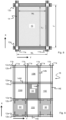
- the borders between neighbouring grid cells run along the centre-line of the horizontal members, as is indicated in Fig. 8 .
- Fig. 9 shows an alternative rail or track system 16 which is made up by elongated members each forming a single track, i.e. a track configured to accommodate only one wheel.
- the borders between neighbouring grid cells run midway between neighbouring elongated members forming the single tracks.
- grid cell 14 comprises a grid opening 15. To the left (West) of grid cell 14, there is an adjacent grid cell 14W comprising a grid opening 15W. Likewise, to the right (East) of grid cell 14, there is an adjacent grid cell 14E comprising a grid opening 15E. Also, below grid cell 14 (South), there is an adjacent grid cell 14S comprising a grid opening 15S, and above grid cell 14 (North), there is an adjacent grid cell 14N comprising a grid opening 15N.
- a footprint 30 of a container handling vehicle is schematically illustrated.
- the footprint 30 is defined by the horizontal extension of the wheels of the vehicle.
- the footprint 30 has a horizontal extent which is less than the horizontal extent of a grid cell.
- a footprint 30' of a container handling vehicle is also schematically illustrated.
- the lower part of the vehicle extends beyond the wheels and the footprint 30' has a horizontal extension which is equal to than the horizontal extension of a grid cell.
- the protruding section 27 may comprise a battery compartment or slot 28 for a rechargeable or a replaceable battery 25.
- a battery compartment or slot 28 for a rechargeable or a replaceable battery 25 may comprise a battery compartment or slot 28 for a rechargeable or a replaceable battery 25.
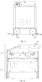
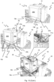
- FIG. 14 An example of a charging and/or battery exchange station 40, hereinafter referred to as a charging station, is shown in Fig. 14 , both in a perspective view ( Fig. 14 A) and in side views along X direction ( Fig. 14 B) and along Y direction ( Fig. 14 C) .
- the charging station 40 is mounted on a charging station base plate 41, which is fixed (directly or indirectly) to neighbouring rails 11a,11b,12a,12b of the track system above a grid column at or near the perimeter of the framework structure.
- the particular grid column containing the charging station 40 will hereinafter be referred to as a charging station cell.
- the charging station 40 shown comprises a vertical charging station column 42 fixed at a lower end 42a to the based plate 41.
- a charging socket 45 is arranged at or near an upper end 42b of the column 42, i.e. opposite to the lower end 42a, and electrically connected to a power supply 44, possibly via a power transformer transforming the charging power to the desired power level.
- the charging socket 45 is further configured to receive a charging plug 46 of the battery 25 installed on each vehicle 3 (see. Fig. 18 ), thereby allowing flow of electric power when the charging plug 46 is electrically coupled to the charging socket 45.
- the charging socket 45 is resiliently attached to the charging station 42, for example such that the position of the charging socket 45 is fixed in an upper (unloaded) position when no external force act on the charging socket 45 and in a lower (loaded) position when the charging socket is exposed to the weight of the electrically connected battery 25.
- the charging socket 45 and the charging plug 46 may of course be interchanged.
- any kind of disconnectable electrical connections between the charging station 40 and the battery 25 is possible.
- An automated storage and retrieval system as described herein may comprise a plurality of such charging stations 40, typically arranged along the perimeter of the track system. However, one or more charging stations 40 may alternatively or additionally be placed further into the track system and/or fully outside of the track system. In the latter configuration, the charging station(s) 40 should be connected to the track system by additional rails in order to allow the vehicles 3 to travel to their respective charging station 40.
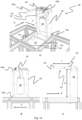
- the first set of wheels 19a-d should contact the underlying track system (see Fig. 15 A-D ) and the second set of wheels 20a-d closest to the charging station 30 should be sufficiently high above the track system in order not to interfere with the tracks along the Y direction.
- the vehicle 3 When wheels 20a and 20b of the second set of have entered the charging station storage cell, and prior to reaching the horizontal position where the charging station 40 is contacting the approaching vehicle 3, the vehicle 3 is lowered towards the track system. The lowering is performed to allow correct alignments with the main battery 25 during the battery exchange process since the weight of the battery 25 forces the charging socket 45 down to its lower (loaded) position as explained above. A lowering of the vehicle 3 also increases the overall stability of the exchange procedure. Typical vertical displacement of the vehicle 3 is 5-15 mm, for example 10 mm.
- the charging station 40 should thus be configured such that the height of the main battery 25 under charge, relative to the track system, is approximately equal to the corresponding height of the battery compartment on the vehicle 3 when the vehicle 3 is in a lowered position.
- an auxiliary battery may be installed, for example in the same or similar way as disclosed in the patent publication WO 2015/104263 A1 , the contents of which are incorporated herein by reference.
- Other solutions may also be envisaged, for example use of external power sources such as live rails, manual interference, etc.
- the available charged battery 25 on the second charging station 40 is mounted onto a battery support 43, which in the example shown in Figs. 14-16 is in form of two guiding pins 43a, 43b extending laterally into the track system from each side of the charging station column's 42 upper end 42b.
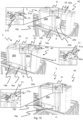
- a release mechanism 50 (see Fig. 17 ) is activated, allowing the battery cover 31 to be tilted around a rotational axis.
- the release mechanism 50 comprises a pivot arm 51 arranged at both sides of the opening of the battery compartment into which the battery 25 is to be inserted.
- each of the protruding ends of the guiding pins 43a,43b displays a tapered section 52 (see Fig. 14A and 14C ).
- a pivot arm contact element 51a of each pivot arm 51 is pushed towards the tapered section 52, thereby enforcing an upward directed pivoting movement of the pivot arm 51 (see Fig. 15A , Fig. 16D and Fig. 17 ).
- This pivot movements releases a security lock 51b (see Figs. 15 and 19 ) allowing the above mentioned tilt of the battery cover 31.
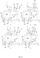
- the operation of the release mechanism 50 is illustrated in each of the sequence drawings in Fig. 15 and in Fig. 17 .
- enlarged area drawings of the release mechanism 50 is added in Fig. 15 A-C and Fig. 15 F .
- the enlarged area drawings clearly show the activation of the pivot arm movement upon contact with the tapered section 52 moving the security lock 51b away from the battery cover 27 and the subsequent entry of the battery 25.
- the guiding pins 43 with the attached battery 28 When the guiding pins 43 with the attached battery 28 has entered a certain distance into the battery compartment 27a (see Figs. 15 B and C ), the guiding pins 43 releases a battery lock 27b, 27c that allows further entry until the battery 25 is fully in its end position within the battery compartment.
- the battery lock 27b,c comprises a battery lock activator 27b in the form of a wheel and one or more blocking teeth 27c extending from the inner walls of the battery cover and into the battery compartment.
- the battery lock activator 27b When the tapered ends 52 of the guiding pins 43a,b contacts the battery lock activator 27b, the battery cover 27 is tilted upwards, thereby displacing the one or more teeth 27c such that the battery 25 and the guiding pins 43a,b may continue the movement deeper into the battery compartment.
- the battery 25 can be electrically connected two both the charging station 40 and i.e. the drive motors for the wheels 19a-d,20a-d.
- the battery compartment tilts back to its initial position such that the teeth 27c physically locks or holds the battery 25 within the battery compartment.
- the teeth 27c may enter dedicated recesses 49a within support rails 49 arranged at both sides of the battery 28 (see Fig. 17 ).
- the battery lock 27b,c may be any physical hindrance within the battery compartment.
- the battery lock may comprise one or more protruding wedges that the battery 25 may surpass in one direction, but not in the other. In this configuration, the wedge shape would act as the battery lock activator 27b.
- the second set of wheels 20a-d of the vehicle 3 is lifted from the track system (typically between 5-15 mm), thereby lifting the overall height of the vehicle 3.
- This operation causes the battery 25 to be released from the battery support 43, for example from dedicated pockets or tracks within the first and second guiding pins 43a,b (see Fig. 14A ).
- the blocking of the battery 28 into the battery compartment 27a has the advantage that the battery 28 cannot be unintentionally displaced within the battery cover 27 during operation.
- the steps for transferring the battery 28 from the vehicle 3 to the charging station 40 are essentially equal or similar to the opposite sequence and direction of the above-mentioned steps of transferring the battery 28 from the charging station 40 to the vehicle 3.
- the vehicle 3 is first raised to both allow the vehicle to enter the charging station storage cell without interference of the second set of wheels 20 with the tracks 11 in the second direction (Y) and to align the operative battery 25 with the charging plug 45 of the charging station 40.
- the charging plug 45 is in the exemplary configuration of Figs. 14-17 in an upper, unloaded position.
- the wedged ends 52 of the first and second guiding pins 43a,b first activate the tilt of the battery compartment via the release mechanism 51, then activate the battery lock 27b,c causing the battery cover to tilt upwards, thereby removing the blocking teeth 27c from the corresponding recesses 49a in the support rail 49.
- both the battery cover and the optional release mechanism 50 may be arranged so that they protrude horizontally in the X direction beyond the otherwise generally vertical side walls 26c and 26d. In this way, the overall capacity of each vehicle 3 in the system 1 may be increased significantly without necessitating making the tracks 11,12 wider.
- a configuration with a protruding release mechanism 50 has an additional advantage in that it allows easy manual unlocking of the battery. That is, the protruding arrangement allows for exertion of sufficient manual force on the release mechanism 50, an operation that would be difficult if for example the release mechanism 50 was arranged deep within the battery cover 27.
- the protruding configuration described above is also beneficial for ensuring early engagement in the charging station 40.
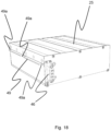
- FIG. 18 An example of a battery 25 is shown in perspective in Fig. 18 .
- One of two support rails 49 is shown protruding from a side wall of the battery 25.
- identical support rail is protruding from the opposite side wall.
- the purpose of the support rails 49 is to both ensure a stable support of the battery 25 on the battery support / guiding pins 43 and to ensure an accurate guiding of the battery 25 into and out of the battery compartment during exchange.
- Fig. 19 shows the battery 25 with support rails 49 being inserted fully within the battery compartment. In the particular configuration shown in Fig. 19 , the battery 25 is approximately half the maximum allowable volume of a battery.
Landscapes
- Engineering & Computer Science (AREA)
- Mechanical Engineering (AREA)
- Transportation (AREA)
- Physics & Mathematics (AREA)
- Power Engineering (AREA)
- Structural Engineering (AREA)
- Mathematical Physics (AREA)
- Life Sciences & Earth Sciences (AREA)
- Manufacturing & Machinery (AREA)
- General Engineering & Computer Science (AREA)
- Quality & Reliability (AREA)
- General Physics & Mathematics (AREA)
- Automation & Control Theory (AREA)
- Civil Engineering (AREA)
- Geology (AREA)
- Sustainable Energy (AREA)
- Sustainable Development (AREA)
- Warehouses Or Storage Devices (AREA)
- Battery Mounting, Suspending (AREA)
- Arrangement Or Mounting Of Propulsion Units For Vehicles (AREA)
Priority Applications (1)
| Application Number | Priority Date | Filing Date | Title |
|---|---|---|---|
| EP24223063.9A EP4549345A1 (de) | 2017-05-16 | 2018-05-15 | Automatisiertes lager- und entnahmesystem |
Applications Claiming Priority (4)
| Application Number | Priority Date | Filing Date | Title |
|---|---|---|---|
| NO20170810A NO344463B1 (en) | 2017-05-16 | 2017-05-16 | Automated storage and retrieval system and method of operating same |
| NO20180586A NO20180586A1 (en) | 2018-04-25 | 2018-04-25 | Charging system for container handling vehicles and method of charging a power supply |
| PCT/EP2018/062578 WO2018210851A1 (en) | 2017-05-16 | 2018-05-15 | Automated storage and retrieval system |
| EP18724873.7A EP3634885B1 (de) | 2017-05-16 | 2018-05-15 | Automatisiertes speicherung- und abrufsystem |
Related Parent Applications (2)
| Application Number | Title | Priority Date | Filing Date |
|---|---|---|---|
| EP18724873.7A Division EP3634885B1 (de) | 2017-05-16 | 2018-05-15 | Automatisiertes speicherung- und abrufsystem |
| EP18724873.7A Division-Into EP3634885B1 (de) | 2017-05-16 | 2018-05-15 | Automatisiertes speicherung- und abrufsystem |
Related Child Applications (1)
| Application Number | Title | Priority Date | Filing Date |
|---|---|---|---|
| EP24223063.9A Division EP4549345A1 (de) | 2017-05-16 | 2018-05-15 | Automatisiertes lager- und entnahmesystem |
Publications (2)
| Publication Number | Publication Date |
|---|---|
| EP4371908A2 true EP4371908A2 (de) | 2024-05-22 |
| EP4371908A3 EP4371908A3 (de) | 2024-07-24 |
Family
ID=62167350
Family Applications (3)
| Application Number | Title | Priority Date | Filing Date |
|---|---|---|---|
| EP23216435.0A Withdrawn EP4371908A3 (de) | 2017-05-16 | 2018-05-15 | Automatisiertes lager- und entnahmesystem |
| EP18724873.7A Active EP3634885B1 (de) | 2017-05-16 | 2018-05-15 | Automatisiertes speicherung- und abrufsystem |
| EP24223063.9A Pending EP4549345A1 (de) | 2017-05-16 | 2018-05-15 | Automatisiertes lager- und entnahmesystem |
Family Applications After (2)
| Application Number | Title | Priority Date | Filing Date |
|---|---|---|---|
| EP18724873.7A Active EP3634885B1 (de) | 2017-05-16 | 2018-05-15 | Automatisiertes speicherung- und abrufsystem |
| EP24223063.9A Pending EP4549345A1 (de) | 2017-05-16 | 2018-05-15 | Automatisiertes lager- und entnahmesystem |
Country Status (8)
| Country | Link |
|---|---|
| US (4) | US11360465B2 (de) |
| EP (3) | EP4371908A3 (de) |
| JP (3) | JP7049369B2 (de) |
| CN (1) | CN110809553B (de) |
| CA (1) | CA3063294A1 (de) |
| ES (1) | ES2971627T3 (de) |
| PL (1) | PL3634885T3 (de) |
| WO (1) | WO2018210851A1 (de) |
Families Citing this family (37)
| Publication number | Priority date | Publication date | Assignee | Title |
|---|---|---|---|---|
| US11858738B2 (en) * | 2013-08-09 | 2024-01-02 | Ocado Innovation Limited | Apparatus for retrieving units from a storage system |
| GB201314313D0 (en) | 2013-08-09 | 2013-09-25 | Ocado Ltd | Apparatus for retrieving units from a storage system |
| NO346327B1 (en) * | 2017-05-16 | 2022-06-07 | Autostore Tech As | Automated storage and retrieval system |
| NO20180586A1 (en) * | 2018-04-25 | 2019-10-28 | Autostore Tech As | Charging system for container handling vehicles and method of charging a power supply |
| US11360465B2 (en) * | 2017-05-16 | 2022-06-14 | Autostore Technology AS | Automated storage and retrieval system |
| NO344464B1 (en) * | 2017-10-19 | 2019-12-23 | Autostore Tech As | Vehicle for an automated storage and retrieval system and method of operating an automated storage and retrieval system |
| EP3737622B1 (de) | 2018-01-09 | 2025-10-15 | Autostore Technology AS | Verschiebungsmechanismus für ein ferngesteuertes fahrzeug |
| GB201807562D0 (en) | 2018-05-09 | 2018-06-20 | Ocado Innovation Ltd | Apparatus and method for charging a robotic load handling device |
| NO345278B1 (en) * | 2019-03-29 | 2020-11-30 | Autostore Tech As | Method and computer program for controlling storage and retrieval of personal storage containers in an automated storage and retrieval system |
| NO349193B1 (en) * | 2019-05-03 | 2025-10-27 | Autostore Tech As | Storage system and method of reinforcing a storage grid structure |
| JP7235106B2 (ja) * | 2019-05-22 | 2023-03-08 | 村田機械株式会社 | 走行車システム及び走行車の制御方法 |
| USD934324S1 (en) * | 2019-06-17 | 2021-10-26 | Autostore Technology AS | Autonomous transport robot |
| CN110239871B (zh) * | 2019-07-15 | 2024-11-19 | 南京翌星自动化系统有限公司 | 一种物流搬运存储系统 |
| CN110255038B (zh) * | 2019-07-15 | 2024-11-19 | 南京翌星自动化系统有限公司 | 一种自动换向搬运设备 |
| EP4010201A1 (de) | 2019-08-09 | 2022-06-15 | Berkshire Grey Operating Company, Inc. | Systeme und verfahren zur bereitstellung von rädern mit variablen federraten |
| NO345918B1 (en) * | 2019-09-16 | 2021-10-18 | Autostore Tech As | Automated storage and retrieval system using an automated loader and methods of replacing power supplies |
| CN111169879A (zh) * | 2019-12-31 | 2020-05-19 | 江苏速升自动化装备股份有限公司 | 一种轮坯立体仓库 |
| GB202003047D0 (en) * | 2020-03-03 | 2020-04-15 | Ocado Innovation Ltd | A grid framework structure |
| DE102020203221A1 (de) | 2020-03-12 | 2021-09-16 | Gebhardt Fördertechnik GmbH | Fahrzeug für ein Lagersystem sowie Ladestation für das Fahrzeug |
| NO20200346A1 (en) * | 2020-03-24 | 2021-09-27 | Autostore Tech As | Delivery vehicle, system and method for moving storage containers between a first conveyor on the delivery vehicle and an external conveyor |
| NO348555B1 (en) * | 2020-03-31 | 2025-03-10 | Autostore Tech As | Automated storage and retrieval system and method for storing and retrieving storage containers |
| CA3169244A1 (en) * | 2020-03-31 | 2021-10-07 | Trond Austrheim | Automated storage tower with multiple rows |
| GB202006089D0 (en) * | 2020-04-24 | 2020-06-10 | Ocado Innovation Ltd | Apparatus and method for charging a load handling device on a grid |
| NO20200499A1 (en) * | 2020-04-28 | 2021-10-29 | Autostore Tech As | Adjustable storage container |
| NO346304B1 (en) * | 2020-06-25 | 2022-05-30 | Autostore Tech As | System and method of operating an automated storage and retrieval system |
| NO346109B1 (en) * | 2020-06-25 | 2022-02-21 | Autostore Tech As | Multiposition search |
| GB202013968D0 (en) * | 2020-09-04 | 2020-10-21 | Ocado Innovation Ltd | A grid framework structure |
| WO2022102265A1 (ja) * | 2020-11-13 | 2022-05-19 | 村田機械株式会社 | 走行車システム |
| NO346544B1 (en) * | 2020-11-30 | 2022-09-26 | Autostore Tech As | A remotely operated picking vehicle, an automated storage and retrieval system, and a method of handling products in the system |
| GB202102023D0 (en) * | 2021-02-12 | 2021-03-31 | Ocado Innovation Ltd | Apparatus for charging a robotic load handling device |
| GB202101996D0 (en) * | 2021-02-12 | 2021-03-31 | Ocado Innovation Ltd | Apparatus for charging a robotic load handling device |
| NO346543B1 (en) * | 2021-03-09 | 2022-09-26 | Autostore Tech As | A storage system featuring covers arrangeable in storage columns |
| NO346982B1 (en) * | 2021-06-30 | 2023-03-27 | Autostore Tech As | System, method and computer program product of determining a position of a container handling vehicle in an automated grid based storage and retrieval system |
| US20250128879A1 (en) * | 2021-08-20 | 2025-04-24 | Ocado Innovation Limited | Determining a kinematic state of a load handling device in a storage system |
| NO348892B1 (en) * | 2021-12-13 | 2025-07-07 | Autostore Tech As | Method for delivering goods to a customer utilizing optical character recognition |
| US11790946B2 (en) * | 2022-02-04 | 2023-10-17 | Seagate Technology Llc | Magnetically repositionable cassettes within a data storage drive |
| GB2619064A (en) * | 2022-05-26 | 2023-11-29 | Ocado Innovation Ltd | A combined power and data unit for a storage and retreival system, and related devices |
Citations (4)
| Publication number | Priority date | Publication date | Assignee | Title |
|---|---|---|---|---|
| WO2015104263A2 (en) | 2014-01-08 | 2015-07-16 | Jakob Hatteland Logistics As | Robot for transporting storage bins |
| WO2015193278A1 (en) | 2014-06-19 | 2015-12-23 | Jakob Hatteland Logistics As | Robot for transporting storage bins |
| WO2016120075A1 (en) | 2015-01-28 | 2016-08-04 | Jakob Hatteland Logistics As | Robot for transporting storage bins |
| WO2017220627A1 (en) | 2016-06-21 | 2017-12-28 | Autostore Technology AS | Charging station with multiple power sources |
Family Cites Families (20)
| Publication number | Priority date | Publication date | Assignee | Title |
|---|---|---|---|---|
| SE375505B (de) | 1969-03-10 | 1975-04-21 | T J R Bright | |
| US4088232A (en) | 1974-04-01 | 1978-05-09 | Clark Equipment Co. | Apparatus with storage cells disposed adjacent vertical shafts having covers and a lift means movable thereabove |
| JPH0966426A (ja) * | 1995-08-30 | 1997-03-11 | Toyota Autom Loom Works Ltd | 生産ライン及び生産ラインシステム |
| WO1997015513A1 (de) | 1995-10-27 | 1997-05-01 | Krups Kompaktlogistik Gmbh | Vorrichtung zum ausziehen von rollpaletten in der kompakt-lagertechnik, sowie rollpalette hierfür |
| JP3059937B2 (ja) * | 1996-05-27 | 2000-07-04 | 三洋電機株式会社 | 電動自転車の充電システム |
| CN201227988Y (zh) * | 2008-05-12 | 2009-04-29 | 梁晓军 | 电动自行车停车充电计费装置 |
| US8687315B2 (en) | 2011-05-11 | 2014-04-01 | International Business Machines Corporation | Data storage system using a media mobility unit (MMU), the MMU, and methods of use thereof |
| JP5830282B2 (ja) | 2011-06-30 | 2015-12-09 | 株式会社岡村製作所 | 物品搬送装置 |
| NL2007566C2 (en) | 2011-10-11 | 2013-04-15 | Lely Patent Nv | Vehicle system. |
| NO335839B1 (no) * | 2012-12-10 | 2015-03-02 | Jakob Hatteland Logistics As | Robot for transport av lagringsbeholdere |
| US9785911B2 (en) | 2013-07-25 | 2017-10-10 | I AM Robotics, LLC | System and method for piece-picking or put-away with a mobile manipulation robot |
| GB201314313D0 (en) * | 2013-08-09 | 2013-09-25 | Ocado Ltd | Apparatus for retrieving units from a storage system |
| GB201404870D0 (en) * | 2014-03-18 | 2014-04-30 | Ocado Ltd | Robotic service device and handling method |
| HUE063992T2 (hu) * | 2015-11-11 | 2024-02-28 | Ocado Innovation Ltd | Robotizált komissiózó rendszerek és berendezések |
| GB201521488D0 (en) * | 2015-12-06 | 2016-01-20 | Ocado Innovation Ltd | Sequencing systems and methods |
| NO20160075A1 (en) | 2016-01-14 | 2017-04-03 | Autostore Tech As | Method for retrieving items from a storage system and storage system for storing and retrieving bins |
| NO20160118A1 (en) * | 2016-01-26 | 2017-07-27 | Autostore Tech As | Remotely operated vehicle |
| GB201603520D0 (en) * | 2016-02-29 | 2016-04-13 | Ocado Innovation Ltd | Robotic service device and handling method |
| CN108698757B (zh) * | 2016-03-03 | 2020-11-24 | 村田机械株式会社 | 输送系统 |
| US11360465B2 (en) | 2017-05-16 | 2022-06-14 | Autostore Technology AS | Automated storage and retrieval system |
-
2018
- 2018-05-15 US US16/614,121 patent/US11360465B2/en active Active
- 2018-05-15 JP JP2019563433A patent/JP7049369B2/ja active Active
- 2018-05-15 EP EP23216435.0A patent/EP4371908A3/de not_active Withdrawn
- 2018-05-15 EP EP18724873.7A patent/EP3634885B1/de active Active
- 2018-05-15 CA CA3063294A patent/CA3063294A1/en active Pending
- 2018-05-15 EP EP24223063.9A patent/EP4549345A1/de active Pending
- 2018-05-15 WO PCT/EP2018/062578 patent/WO2018210851A1/en not_active Ceased
- 2018-05-15 PL PL18724873.7T patent/PL3634885T3/pl unknown
- 2018-05-15 ES ES18724873T patent/ES2971627T3/es active Active
- 2018-05-15 CN CN201880039767.1A patent/CN110809553B/zh active Active
-
2022
- 2022-03-25 JP JP2022049402A patent/JP7483778B2/ja active Active
- 2022-05-03 US US17/661,844 patent/US11846935B2/en active Active
-
2023
- 2023-11-09 US US18/505,777 patent/US12210339B2/en active Active
-
2024
- 2024-05-01 JP JP2024074310A patent/JP7709569B2/ja active Active
- 2024-12-13 US US18/981,041 patent/US20250110490A1/en active Pending
Patent Citations (4)
| Publication number | Priority date | Publication date | Assignee | Title |
|---|---|---|---|---|
| WO2015104263A2 (en) | 2014-01-08 | 2015-07-16 | Jakob Hatteland Logistics As | Robot for transporting storage bins |
| WO2015193278A1 (en) | 2014-06-19 | 2015-12-23 | Jakob Hatteland Logistics As | Robot for transporting storage bins |
| WO2016120075A1 (en) | 2015-01-28 | 2016-08-04 | Jakob Hatteland Logistics As | Robot for transporting storage bins |
| WO2017220627A1 (en) | 2016-06-21 | 2017-12-28 | Autostore Technology AS | Charging station with multiple power sources |
Also Published As
| Publication number | Publication date |
|---|---|
| JP2020520329A (ja) | 2020-07-09 |
| US11360465B2 (en) | 2022-06-14 |
| PL3634885T3 (pl) | 2024-06-24 |
| WO2018210851A1 (en) | 2018-11-22 |
| JP2024096298A (ja) | 2024-07-12 |
| JP7709569B2 (ja) | 2025-07-16 |
| US20220260982A1 (en) | 2022-08-18 |
| US11846935B2 (en) | 2023-12-19 |
| EP3634885A1 (de) | 2020-04-15 |
| EP4371908A3 (de) | 2024-07-24 |
| US20250110490A1 (en) | 2025-04-03 |
| US20240126249A1 (en) | 2024-04-18 |
| EP4549345A1 (de) | 2025-05-07 |
| CN110809553A (zh) | 2020-02-18 |
| JP2022075973A (ja) | 2022-05-18 |
| JP7049369B2 (ja) | 2022-04-06 |
| CA3063294A1 (en) | 2018-11-22 |
| JP7483778B2 (ja) | 2024-05-15 |
| EP3634885B1 (de) | 2024-01-24 |
| US20210155407A1 (en) | 2021-05-27 |
| CN110809553B (zh) | 2021-10-15 |
| EP3634885C0 (de) | 2024-01-24 |
| US12210339B2 (en) | 2025-01-28 |
| ES2971627T3 (es) | 2024-06-06 |
Similar Documents
| Publication | Publication Date | Title |
|---|---|---|
| US11846935B2 (en) | Automated storage and retrieval system | |
| US11912501B2 (en) | Automated storage and retrieval system | |
| WO2019206490A1 (en) | An automated storage and retrieval system with a charging station for charging of a replaceable power supply of a container handling vehicle | |
| HK40098971A (en) | Automated storage and retrieval system | |
| HK40118418A (zh) | 自动存储和取回系统 | |
| HK40021302B (en) | Automated storage and retrieval system | |
| HK40021302A (zh) | 自动化存储和取回系统 | |
| HK40021290A (en) | Automated storage and retrieval system | |
| HK40021290B (zh) | 自动存储和取回系统 | |
| NO344463B1 (en) | Automated storage and retrieval system and method of operating same |
Legal Events
| Date | Code | Title | Description |
|---|---|---|---|
| PUAI | Public reference made under article 153(3) epc to a published international application that has entered the european phase |
Free format text: ORIGINAL CODE: 0009012 |
|
| STAA | Information on the status of an ep patent application or granted ep patent |
Free format text: STATUS: THE APPLICATION HAS BEEN PUBLISHED |
|
| AC | Divisional application: reference to earlier application |
Ref document number: 3634885 Country of ref document: EP Kind code of ref document: P |
|
| AK | Designated contracting states |
Kind code of ref document: A2 Designated state(s): AL AT BE BG CH CY CZ DE DK EE ES FI FR GB GR HR HU IE IS IT LI LT LU LV MC MK MT NL NO PL PT RO RS SE SI SK SM TR |
|
| PUAL | Search report despatched |
Free format text: ORIGINAL CODE: 0009013 |
|
| AK | Designated contracting states |
Kind code of ref document: A3 Designated state(s): AL AT BE BG CH CY CZ DE DK EE ES FI FR GB GR HR HU IE IS IT LI LT LU LV MC MK MT NL NO PL PT RO RS SE SI SK SM TR |
|
| RIC1 | Information provided on ipc code assigned before grant |
Ipc: B65G 1/04 20060101AFI20240617BHEP |
|
| STAA | Information on the status of an ep patent application or granted ep patent |
Free format text: STATUS: THE APPLICATION IS DEEMED TO BE WITHDRAWN |
|
| 18D | Application deemed to be withdrawn |
Effective date: 20250125 |